
Abstract
To better evaluate the spatial steering effect of directional perforation hydraulic fractures, evaluation indexes for the spatial steering effect are first proposed in this paper. Then, these indexes are used to quantitatively evaluate existing physical experimental results. Finally, with the help of RFPA2D-Flow software, the influence of perforation length and azimuth on the spatial steering process of hydraulic fracture are quantitatively analysed using four evaluation indexes. It is shown by the results that the spatial deflection trajectory, deflection distance, deflection angle and initiation pressure of hydraulic fractures can be used as quantitative evaluation indexes for the spatial steering effect of hydraulic fractures. The deflection paths of directional perforation hydraulic fractures are basically the same. They all gradually deflect to the maximum horizontal principal stress direction from the perforation hole and finally represent a double-wing bending fracture. The deflection distance, deflection angle and initiation pressure of hydraulic fractures increase gradually with increasing perforation azimuth, and the sensitivity of the deflection angle to the perforation azimuth of hydraulic fractures also increases. With increasing perforation length, the deflection distance of hydraulic fractures increases gradually. However, the deflection angle and initiation pressure decrease gradually, as does the sensitivity.
Keywords
Introduction
In recent years, with the continuous development of hydraulic fracturing, conventional perforation and spiral perforation have been gradually improved for directional perforation hydraulic fracturing, which is advantageous to expand hydraulic fractures (Gehne and Benson, 2019; Lu and Huang, 2020; Lu et al., 2020a, 2020b; Nandlal and Weijermars, 2019; Ogata et al., 2020). Directional perforation hydraulic fracturing has gradually become widely used because it can specifically construct the expansion path of required hydraulic fractures, maximize reservoir reconstruction volume, alleviate problems such as fast-time water appearance and poor water injection effect of a well caused by linear fracture connection, and thus improve the effect of hydraulic fracturing construction (Hossain et al., 2000; Qi et al., 2018; Liu et al., 2018; Zhang et al., 2020; Zhu et al., 2015). The morphology of hydraulic fractures generated by directional perforation is the key to evaluating whether this technique has been successfully implemented. However, due to reservoir stress differences, mechanical properties of reservoir rock, wellbore radius, perforation parameters and injection pressure, hydraulic fractures deflect to different degrees after initiation at the perforation hole (Chen et al., 2017; Duan et al., 2021; Guo et al., 2020; Liu et al., 2021; Lu and He, 2020; Lu et al., 2020b; Lyu et al., 2020; Song et al., 2020). It is very important to quantitatively evaluate the influence of these factors on the fracturing effect of directional perforation hydraulic fracturing. It is also important to determine reasonable perforation and fracturing operation parameters and to ensure the transformation effect of directional perforation hydraulic fracturing.
The main purpose of hydraulic fracturing is to generate new fractures in a reservoir and connect or expand old fractures to improve reservoir permeability (Guo et al., 2018; He et al., 2020; Li et al., 2018; Zhong et al., 2020). Accurately describing the initiation pressure and expansion path of hydraulic fractures is most important in hydraulic fracturing. At present, a series of laboratory tests, theoretical calculations and numerical simulations on the critical water pressure and propagation path of hydraulic fractures have been carried out. In the laboratory, two pre-setting symmetrical directional perforations are pre-settled in a rock test sample. Wang et al. studied the influence of the ground stress difference and prefabricated fracture dip on the initiation and expansion morphology of hydraulic fractures by combining physical tests and numerical simulations (Dong and Tang, 2019; Wang et al., 2015). Abass et al. studied the change in initiation pressure and propagation path of hydraulic fractures under the conditions of vertical and horizontal wells based on physical tests (Abass et al., 1994). Liu and Zhu et al. studied the influence of pre-set crack dip on the initiation and propagation of hydraulic fractures by means of physical tests and numerical simulations (Liu et al., 2018; Zhu et al., 2015). Chen and Jiang Hu et al. explored the influence of perforation orientation and horizontal principal stress difference on the initiation pressure and morphology of hydraulic fractures through physical experiments on large-scale true triaxial hydraulic fracturing (Chen et al., 2010; Jiang et al., 2009, 2014). Numerical simulation methods mainly include the finite element method (Bao et al., 2014, 2015; Hunsweck et al., 2013; Zhang and Chen, 2010a; Zhang and Chen, 2010b) and the extended finite element method (Daux et al., 2000; Moës and Belytschko, 2002; Sukumar et al., 2000). Dong and Tang et al. used different fracture criteria to study the effect of reservoir ground stress difference, mechanical parameters, wellbore and perforation size and injection water pressure on hydraulic fracture initiation characteristics under the conditions of single-hole and double-hole perforation directional fracturing (Dong et al., 2018; Tang et al., 2017). Using the extended finite element method and the displacement discontinuity method, Wang and Zhang et al. studied the expansion path of hydraulic fractures under two symmetric directional perforation conditions. Although the effect of the wellbore was considered in the model, a constant wellbore radius and perforation length were assumed without the effect of the ground stress difference (Wang, 2015; Zhang et al., 2011). Chen et al. studied the optimization method of directional perforation initiation and perforation, but the influence of perforation length was not considered, and the fracture expansion path under different working conditions was not described (Chen et al., 2017). Based on the extended finite element method, Sepehri et al. simulated fracture propagation under different perforation orientations and horizontal stress differences (Sepehri et al., 2015). A fluid-solid coupled model was established by Shi Jihui et al. and used to study the synchronous propagation and steering of directional perforation hydraulic fractures. It was pointed out that the perforation azimuth, fracturing fluid injection rate and horizontal stress difference are important factors affecting the initiation pressure and deflection radius of hydraulic fractures (Shi et al., 2020). A coupling model of hydraulic fracturing was built by Chen Junbin et al. based on the maximum tensile stress criterion and stress intensity factor. The model was used to study the influence of perforation azimuth, perforation length and perforation phase angle on the initiation and expansion of hydraulic fractures (Chen et al., 2017). A fluid-solid coupling model of the steering fracture was established by Wang Xiaolong et al. The effects of the fluid injection parameters, such as the injection rate and the viscosity of the fracturing fluid, on the deflection propagation of hydraulic fractures were simulated (Wang et al., 2018a, 2018b). The concept of the deflection angle of hydraulic fractures was proposed by Wang et al. to quantitatively analyse the steering effect of hydraulic fractures (Dong and Tang, 2019; Wang et al., 2018a).
At present, two indexes, initiation pressure and morphology of hydraulic fractures, are mostly used to describe the deflection of hydraulic fractures. However, the deflection distance and deflection angle of hydraulic fractures are also two key indexes to evaluate the steering effect of directional perforation hydraulic fracturing. Therefore, the deflection distance and deflection angle of hydraulic fractures are first introduced to evaluate the spatial steering effect of directional perforation hydraulic fractures. Then, the four indexes are used to quantitatively evaluate the existing physical experiments. Meanwhile, with the help of RFPA2D-Flow software, the influences of perforation length and perforation azimuth on the deflection process of directional perforation were analysed by using these four indexes. The results of this paper can provide an important reference for the quantitative evaluation of the fracturing effect and the operation parameter optimization of directional perforation hydraulic fracturing.
Evaluation indexes of the spatial steering effect of directional perforation hydraulic fractures
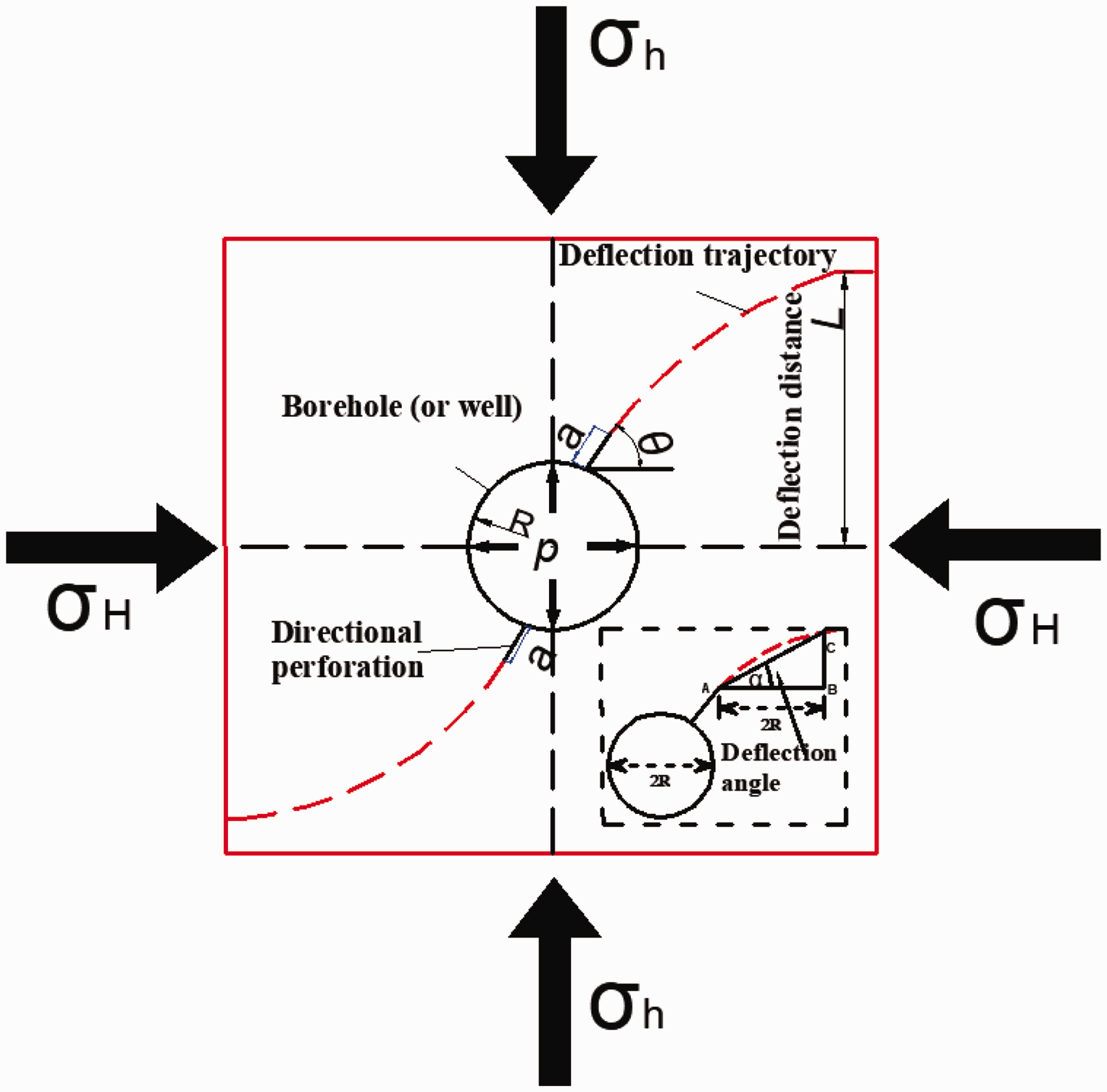
In this paper, the deflection trajectory, deflection distance, deflection angle (Figure 1) and initiation pressure of hydraulic fractures are introduced to evaluate the steering effect of directional perforation hydraulic fractures. Among them, the deflection trajectory, deflection distance and deflection angle of hydraulic fractures belong to geometric evaluation, while the initiation pressure of hydraulic fracture belongs to mechanical evaluation.
Geometric evaluation indexes of the spatial steering effect of hydraulic fractures. (a) Deflection trajectory of hydraulic fracture obtained from physical experiment (Jiang et al., 2009). (b) Deflection trajectory of hydraulic fracture obtained from numerical simulation.
There are 1-shaped, Y-shaped, and cross-shaped morphologies of directional perforation hydraulic fractures. For the above three different morphologies, the shape and propagation process of the 1-shaped directional perforation hydraulic fractures is relatively easiest. Therefore, in this paper, the spatial steering effect of 1-shaped directional perforation hydraulic fracture is selected to quantitatively evaluate and analyse its spatial steering effect. In Figure 1, σH and σh are the maximum and minimum horizontal principal stresses, respectively. a is the directional perforation length, θ is the azimuth angle of the perforation, and L is the deflection distance of the hydraulic fracture. p is the water injection pressure; R is the radius of the wellbore or borehole; α is the deflection angle of the hydraulic fracture.
Deflection trajectory of hydraulic fractures
According to the classical theory, hydraulic fractures expand along the path of least resistance. In most cases, the maximum stress is in the vertical direction, so the optimal fracture surface is vertical, and its direction is along the direction of the maximum horizontal principal stress. That is, the hydraulic fracture expands along the direction perpendicular to the minimum horizontal principal stress in the far field. The hydraulic fracture gradually deflects to the direction of maximum principal stress with increasing propagation length. As a result, the deflection trajectory of a hydraulic fracture is formed in the rock mass. It can also be called the deflection path or deflection track of hydraulic fractures. In this paper, the deflection trajectory (Figure 1) is used as an index to evaluate the spatial steering law of directional perforation hydraulic fractures.
Deflection distance of hydraulic fractures
In the far field, hydraulic fractures propagate along the direction perpendicular to the minimum horizontal principle stress. The deflection distance is the distance from the end point of the deflection trajectory of the hydraulic fracture to the straight line through the centre of the well or borehole and along the maximum principal stress. In this paper, the deflection distance L of hydraulic fractures (Figure 1) is used as an index to evaluate the spatial steering of directional perforating hydraulic fractures. The deflection distance of hydraulic fractures can be divided into the deflection distance of the left wing, deflection distance of the right wing and average deflection distance of the left and right wings.
Deflection angle of hydraulic fractures
In this paper, the deflection angle is used to quantitatively analyse the spatial steering effect of hydraulic fractures. The deflection angle of a hydraulic fracture is defined as follows. (1) A line segment AB with a length equal to the perforation diameter (2 R) is made along the horizontal direction starting from the initial perforation end A. (2) Then, a vertical line perpendicular to AB is drawn intersecting with the deflection trajectory at point C. (3) The angle between line segments AC and AB is defined as the deflection angle, which is shown in the black dotted box in Figure 1. At the same time, it is stipulated that the larger the deflection angle is, the larger the area of the stimulated reservoir connected by the hydraulic fracture. This can be explained by the fact that the hydraulic fracture with a larger deflection angle can expand far away from the initial perforation. As a result, a larger stimulated reservoir area is formed, and a better fracturing effect is obtained (Wang et al., 2018a). Therefore, the deflection angle can be selected to measure the deflection degree of hydraulic fractures under different working conditions and used to analyse the engineering effect of directional perforation hydraulic fracturing.
Initiation pressure of hydraulic fractures
When oriented perforation is first conducted around the borehole (or wellbore), water enters the end of the open perforations. Under the action of water pressure, the stress state of rock around the borehole (or wellbore) will change. When the maximum stress concentration occurs at the end of the perforation, hydraulic fracture will preferentially occur at the end of the perforation. The hydraulic fracture initiates from the perforation end and then continues to expand. However, it gradually deflects towards the direction of maximum horizontal principal stress. The water pressure is called the initiation pressure of the hydraulic fracture when it begins to initiate.
Actual application of evaluation indexes of the spatial steering effect of directional perforation hydraulic fractures
The deflection trajectory, deflection distance, deflection angle and initiation pressure are used to evaluate the results of the numerical simulation and existing physical experiments.
Spatial steering physical experiments of directional perforation hydraulic fractures
A physical experiment was conducted by Jiang Hu et al. to study the spatial deflection rules of directional perforation hydraulic fractures. The physical experiments are simulated by concrete specimens with dimensions of 300 mm × 300 mm × 300 mm. The specimens were mixed with ordinary 32.5 R cement and quartz sand (particle size 0.125 mm) in a volume ratio of 1:1. At the same time, the specimens are pre-set with steel pipes with an external diameter of 20 mm and an internal diameter of 15 mm. A simulated wellbore with a 2 mm diameter small hole is used to simulate the perforating hole. The angle θ between the perforating hole and the maximum horizontal principal stress is set at 60° (see Figure 1). The basic parameters of the specimen are shown in Table 1. The maximum horizontal principal stress σH and the minimum horizontal principal stress σh are 6 MPa and 1 MPa, respectively. It was shown by the physical experiment that the initiation pressure of hydraulic fractures is 15.55 MPa, and the spatial deflection trajectory of hydraulic fracture is shown in Figure 2(a) (Jiang et al., 2009).
Basic sample parameters (Jiang et al., 2009).
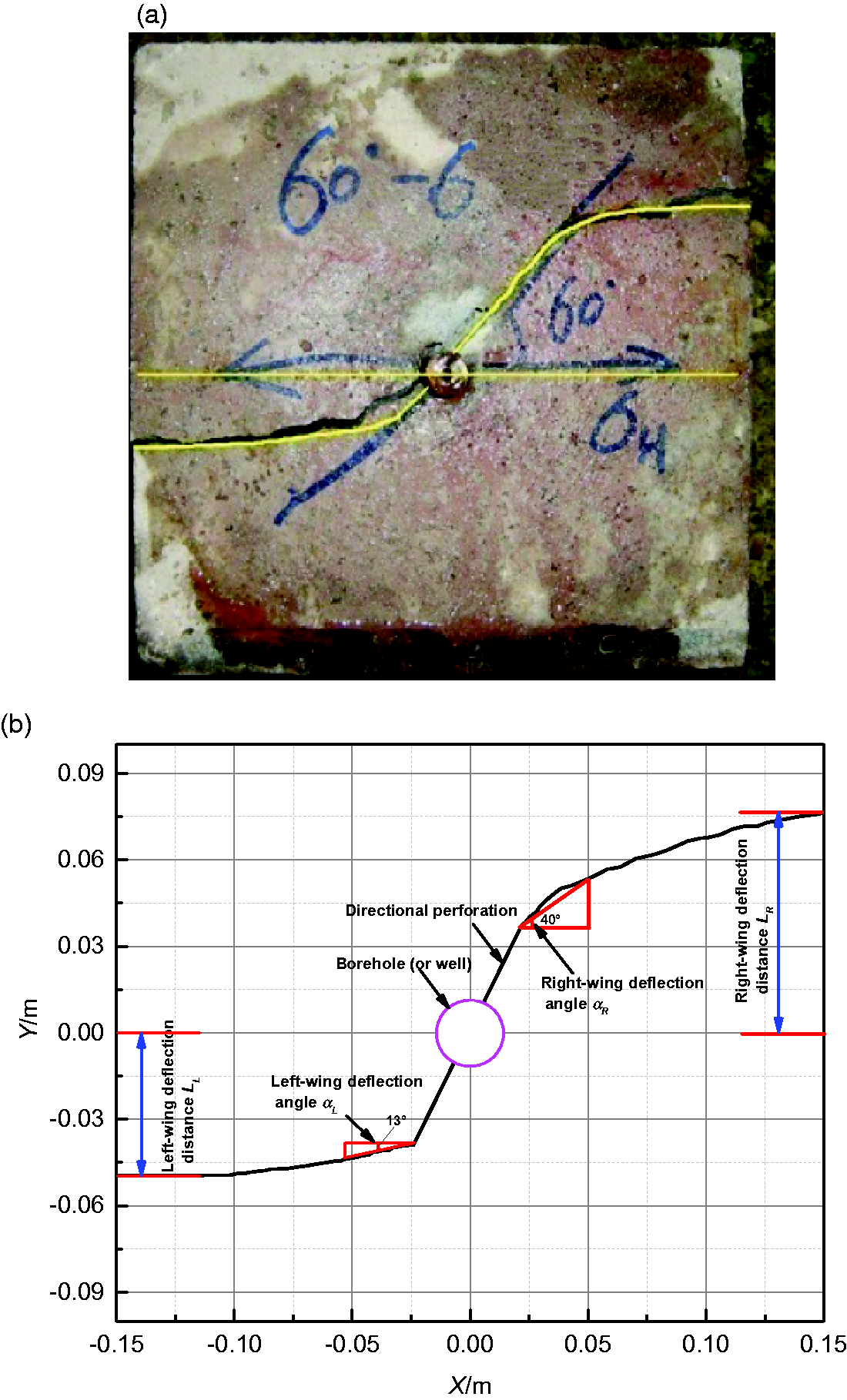
Spatial deflection trajectory of directional perforation hydraulic fracture. (a) Deflection trajectory of hydraulic fracture obtained from physical experiment; (b) Deflection trajectory of hydraulic fracture obtained from numerical simulation.
The deflection trajectory, deflection distance and deflection angle can be obtained by quantitively extracting the hydraulic fracture (Figure 2(b)). Figure 2(b) shows that (1) the hydraulic fracture first initiates along the perforation and then gradually deflects towards the direction of the maximum horizontal principal stress. A two-wing bending fracture, which is not completely symmetrical to the wellbore or borehole centre, is eventually formed. The spatial steering process of the directional perforation hydraulic fracture can be observed intuitively from the deflection trajectory. (2) The deflection distance LL of the left-wing hydraulic fracture (X < 0) is 4.9 cm, and the deflection distance LR of the right-wing hydraulic fracture (X > 0) is 8.3 cm. The deflection distance LR of the right wing of the hydraulic fracture (X > 0) is greater than the deflection distance LL of the left wing hydraulic fracture (X < 0). This also indicates that the spatial deflection morphologies of the left-wing and right-wing hydraulic fractures are asymmetric. (3) The deflection angle αL of the left-wing hydraulic fracture (X < 0) is 13°, and the deflection angle αR of the right-wing hydraulic fracture (X > 0) is 40°. The deflection angle αR of the right-wing hydraulic fracture (X > 0) is greater than the deflection angle αL of the left-wing hydraulic fracture (X < 0). This also indicates the asymmetry of the spatial deflection of the left and right hydraulic fractures, which is consistent with the variation rule reflected by the deflection distance of the hydraulic fracture. (4) The greater the deflection angle of the hydraulic fracture is, the greater the deflection distance. The deflection distance is positively correlated with the deflection angle of hydraulic fractures.
Numerical simulation of the spatial steering process of directional perforation hydraulic fractures
A brief introduction to the numerical code, RFPA2D-Flow
RFPA2D-Flow is a two-dimensional finite element code designed to simulate the fracture and failure processes of quasi-brittle materials such as rock. In the software, the finite element method is employed to obtain the stress and fluid flow fields. The coupling between the stress/strain and fluid flow in the deforming rock mass is governed by Biot’s consolidation theory. The main governing equations in the software can be found in the literature (Li et al., 2011, 2013).
Establishment of the mathematical model and parameter selection
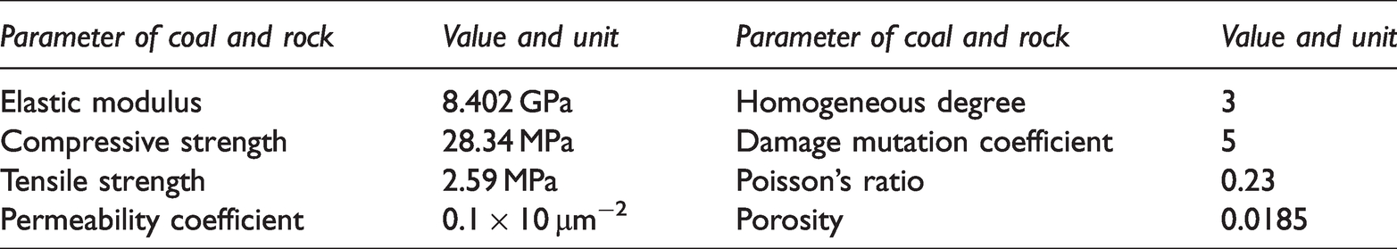
In this numerical simulation, a two-dimensional plane strain model with a size of 300 mm × 300 mm is adopted (Figure 3). The impermeable boundary of the model is restrained by confining pressure. The centre of the borehole with a diameter of 20 mm coincides with the centre of the two-dimensional plane model. The model is divided into 300 × 300 cells. Two directional perforations are represented by the symbols AB and CD. The perforation azimuth θ (the angle between the direction of the perforation and the maximum horizontal principal stress) is 60°, and its length a is 30 mm. The maximum horizontal principal stress σH is 6 MPa, and the minimum vertical principal stress σh is 1 MPa. The initial water pressure applied in the hole is 0 MPa, and the increment of water pressure for each step is 0.2 MPa. The parameters selected for the numerical simulation are shown in Table 2. Homogenous degree, shown in Table 2, is a parameter determined by the shape of the distribution function, which in turn determines the degree of hetero-geneity of the material. A larger homogenous degree indicates a more homogeneous material. Systematic studies of the homogeneity index have been conducted previously (Li et al., 2013).
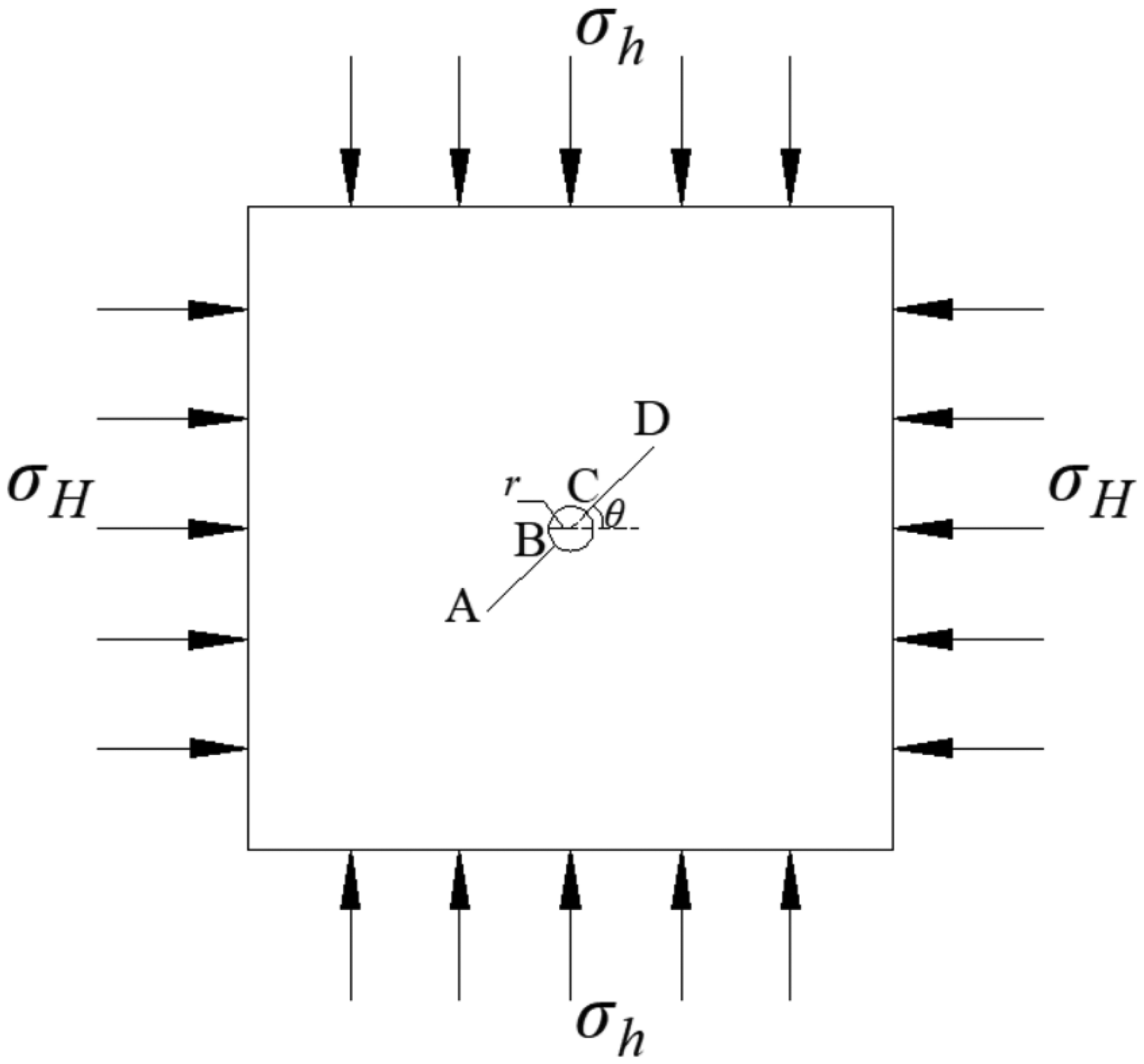
Geometric model of directional perforation hydraulic fracturing.
Numerical simulation parameters.
Influencing factors of the hydraulic fracture spatial steering process
The software is used to study the influence of perforation length and perforation azimuth on the spatial steering process of directional perforation hydraulic fractures. In this paper, the deflection trajectory, deflection distance, deflection angle and initiation pressure of hydraulic fractures are introduced to evaluate the steering effect of directional perforation hydraulic fractures. Among them, the deflection trajectory, deflection distance and deflection angle of hydraulic fractures belong to geometric evaluation, while the initiation pressure of hydraulic fracture belongs to mechanical evaluation. In the existing method, the index of fracture initiation pressure is often seen in the quantitative evaluation of hydraulic fracture. The other three indexes are rarely seen in the existing research.
Influence of perforation length on the hydraulic fracture spatial steering process
The perforation length was gradually changed to 20 mm, 30 mm, 40 mm, 50 mm, and 60 mm to study the influence of the perforation length on the spatial steering process of directional perforation hydraulic fractures.
The deflection trajectory of hydraulic fractures under different perforation lengths is shown in Figure 4. (1) The deflection trajectories of hydraulic fractures under different perforation lengths are basically the same. All of them are nearly double-wing bending fractures. The hydraulic fracture gradually deflects towards the direction of maximum horizontal principal stress after it starts to crack at one end of the directional perforation. The deflection amplitude first increases and then decreases. The deflection distance of hydraulic fractures is different with the change in perforation length. The larger the perforation length is, the larger the deflection distance of hydraulic fractures. (2) When the perforation length a is 20 mm, 30 mm, 40 mm, 50 mm and 60 mm, the deflection distances of the left-wing hydraulic fracture (X < 0) are 0.05349 m, 0.0703 m, 0.07185 m, 0.07348 m and 0.0744 m, respectively, and the deflection distances of the right-wing hydraulic fracture (X > 0) are 0.05429 m, 0.07605 m, 0.07936 m, 0.08395 m and 0.09692 m, respectively. The average deflection distances of the left-wing and right-wing hydraulic fractures are 0.05389 m, 0.07318 m, 0.07561 m, 0.07871 m, and 0.08566 m, respectively. This indicates that with increasing perforation length, both the left-wing or right-wing deflection distance of the unilateral side and the average deflection distance of the left-wing and right-wing hydraulic fractures on both the left and right sides increase. At the same time, it also indicates that the increase in perforation length is not helpful to the deflection distance of hydraulic fractures, and the effect of the effective connection among reservoirs is also worse during fracture propagation.
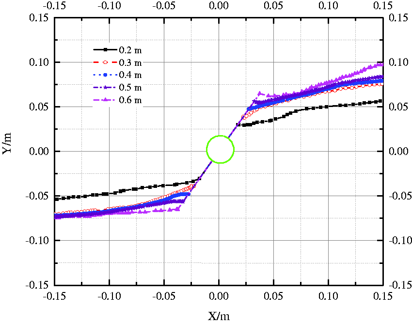
Deflection trajectory of hydraulic fracture under different perforation length.
It can be seen from Figure 5 that (1) the relationship between the deflection angle of the hydraulic fracture and perforation length conforms to the linear change rule θ = −38.5a + 28.8, and the correlation coefficient R2 is 0.89. (2) The tangential derivative of the fitting curve is negative, which indicates that the deflection angle of the hydraulic fracture decreases gradually with increasing perforation length. At the same time, it also indicates that a longer perforation length results in a worse effect of effective reservoir connectivity. (3) When the perforation length a is not larger than 0.5 m, the deflection angle of hydraulic fracture changes significantly between 13° and 18° with the change in perforation azimuth. When the perforation length a is greater than 0.5 m, the change in the deflection angle is not obvious between 1° and 6° with the change in perforation azimuth. This indicates that the sensitivity between the deflection angle of the hydraulic fracture and the perforation azimuth decreases gradually with increasing perforation length.
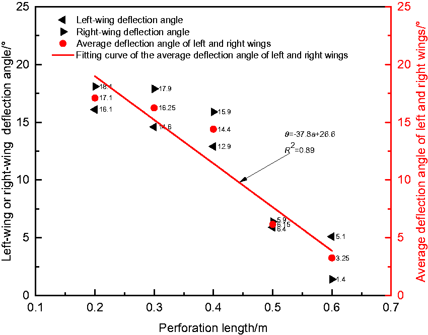
Deflection angle of hydraulic fracture under different perforation length.
It can be seen from Figure 6 that (1) the relationship between the average deflection distance L of the hydraulic fracture and the perforation length a conforms to the change rule of quadratic polynomial L = 0.02177 + 0.00206a-1.715e-5a2, and the correlation coefficient R2 is 0.91886. (2) When the perforation length is a constant, the deflection distance of the right-wing hydraulic fracture (X > 0) is greater than that of the left-wing hydraulic fracture (X < 0). The deflection distance difference between the right-wing and left-wing hydraulic fractures with increasing perforation length. (3) The tangent derivative of the average deflection distance fitting curve of the left-wing and right-wing hydraulic fractures gradually decreases. This indicates that the sensitivity of the deflection distance of the hydraulic fracture to the perforation length gradually decreases with increasing perforation length.
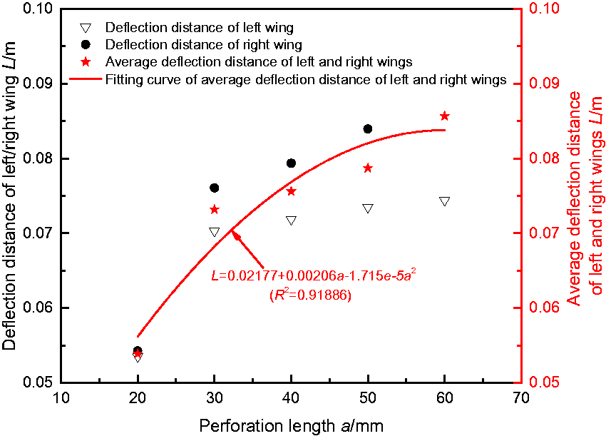
Deflection distance of hydraulic fracture under different perforation length.
In Figure 7, the initiation pressure of hydraulic fracture decreases gradually with increasing perforation length. This result is consistent with the rule obtained by Dong Zhuo et al. using the fracture growth increment method and Chen et al. using the numerical calculation method (Chen et al., 2013; Dong and Tang, 2019).
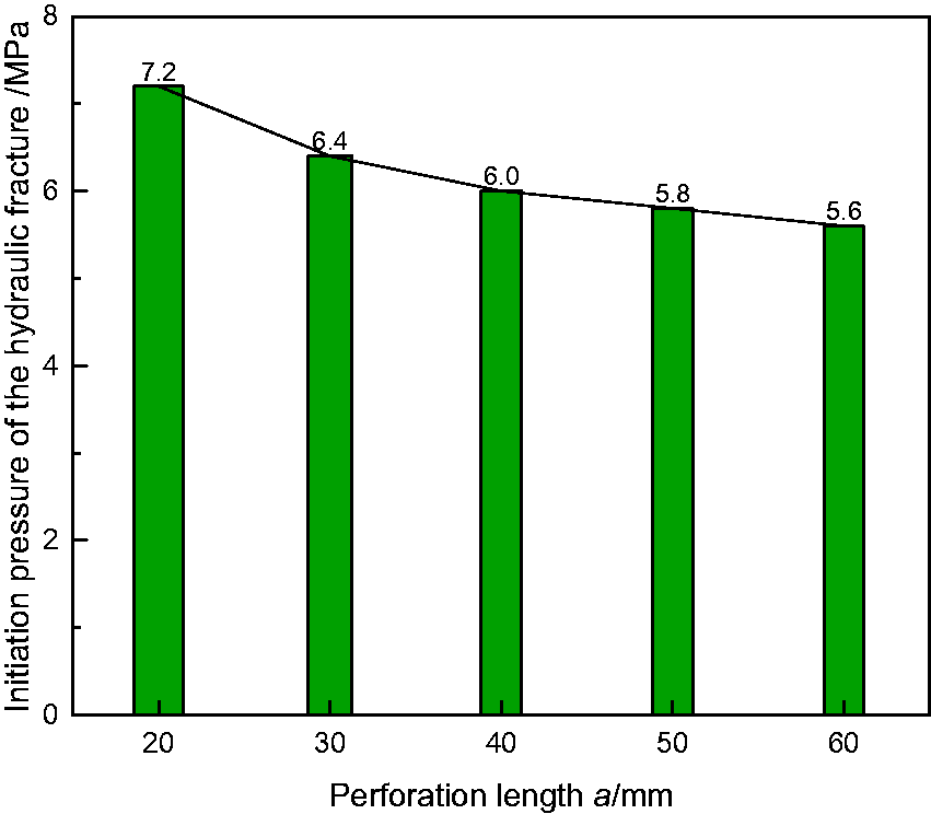
Initiation pressure of the hydraulic fracture under different perforation length. (a) Deflection trajectory of hydraulic fracture. (b) Deflection distance of hydraulic fracture.
Influence of perforation azimuth on the spatial steering process of the hydraulic fracture
The influence of perforation azimuth on the spatial steering process of hydraulic fractures is studied by gradually changing the perforation azimuth angle to 15°, 30°, 45°, 60° and 75°.
Figure 8(a) shows that when the perforation azimuth angle is 15°, 30°, 45°, 60° and 75°, the average deflection distances of the hydraulic fracture are 0.024 m, 0.032 m, 0.045 m, 0.073 m and 0.104 m, respectively. This indicates that when the perforation azimuth angle is small, the hydraulic fracture quickly deflects towards the direction of maximum principal stress with increasing propagation. With the increase in the perforation azimuth, the initiation angle at the beginning of the fracture propagation is larger. Therefore, the hydraulic fracture gradually deflects towards the direction of maximum principal stress after a certain distance of expansion.
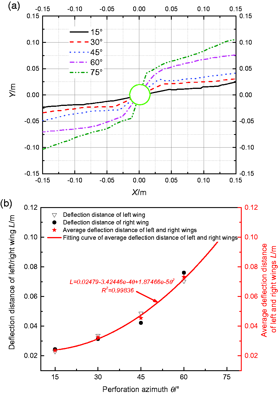
Deflection trajectory and deflection distance of hydraulic fracture under different perforation azimuth. (a) Deflection trajectory of hydraulic fracture; (b) Deflection distance of hydraulic fracture.
The deflection distance of the hydraulic fracture and the perforation azimuth is illustrated in Figure 8(b). It can be seen from Figure 8(b) that (1) the relationship between the deflection distance L of hydraulic fracture and the perforation azimuth θ conforms to the change rule of quadratic polynomial L = 0.02479–3.42446e-4θ + 1.87466e-5θ2, and the correlation coefficient R2 is 0.99836. The derivative of the fitted curve increases with increasing perforation azimuth. It is suggested that the sensitivity between the deflection distance of the hydraulic fracture and perforation azimuth gradually rises with increasing perforation azimuth. With increasing perforation azimuth, hydraulic fractures become more tortuous near the borehole (or wellbore). (2) For every 15° increase in the perforation azimuth, the corresponding deflection distance increases by 0.08 m, 0.13 m, 0.28 m and 0.31 m. This indicates that with increasing perforation azimuth, the variation amplitude of the hydraulic fracture deflection distance also gradually increases. As a result, the connected reservoirs are also more extensive.
It can be observed from Figure 9 that (1) the relationship between the deflection angle of hydraulic fracture and the perforation azimuth conforms to the linear change rule θ = 0.44a-8.95, and the correlation coefficient R2 is 0.84. (2) The slope of the fitting curve is positive, which means that the deflection angle of the hydraulic fracture gradually increases with increasing perforation azimuth. The larger the perforation azimuth angle, the wider the effective reservoir range that can be connected during the deflection of the hydraulic fracture. (3) For the perforation azimuth θ not larger than 45°, the change, which is between 1.4° and 5°, of the hydraulic fracture deflection angle is not obvious. When the perforation azimuth θ is greater than 45°, the deflection angle of hydraulic fracture changes significantly between 21.5° and 26.3°. This shows that the sensitivity between the deflection angle of the hydraulic fracture and the perforation azimuth increases gradually with increasing perforation azimuth.
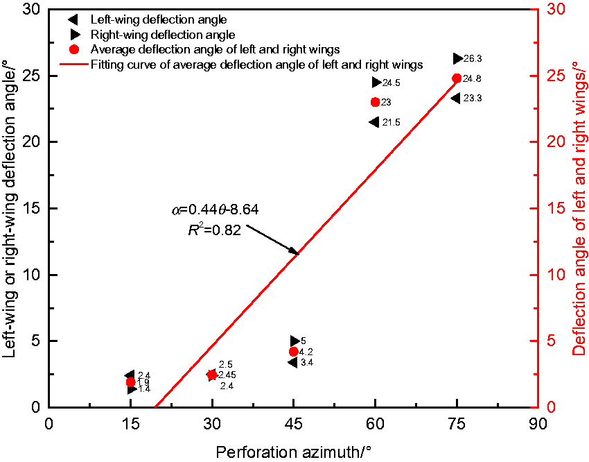
Deflection distance of hydraulic fracture under different perforation azimuth.
Figure 10 shows that the initiation pressure increases nonlinearly with increasing perforation azimuth. When the perforation azimuth is 15°, 30°, 45°, 60° and 75°, the corresponding initiation pressure of the hydraulic fracture is 5.2 MPa, 5.8 MPa, 6.2 MPa, 6.4 MPa and 6.6 MPa, respectively. That is to say, the initiation pressure of hydraulic fracture increases gradually with increasing perforation azimuth.
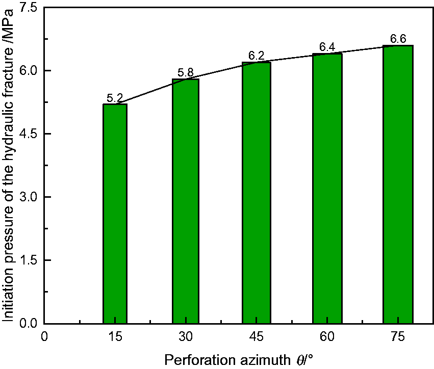
Initiation pressure of hydraulic fracture under different perforation azimuth.
Conclusions
The first three indexes of the deflection trajectory, deflection distance, deflection angle are geometric evaluation indexes, and the initiation pressure of hydraulic fracture is the mechanical evaluation index. These four indexes can be used to describe the expansion process and quantitatively evaluate the influence of parameters such as perforation length and perforation azimuth on the spatial steering effect of directional perforation hydraulic fractures. The deflection trajectories under different perforation lengths and perforation azimuths are basically the same. All the hydraulic fractures gradually deflect towards the direction of maximum horizontal principal stress after they initiate from the perforation end and finally present two-wing bending fractures. The deflection distance, deflection angle and initiation pressure of the hydraulic fracture increase with increasing perforation azimuth. The sensitivity between the deflection angle of the hydraulic fracture and the perforation azimuth increases with increasing perforation azimuth. With increasing perforation length, the deflection distance of the hydraulic fracture increases, but the deflection angle and initiation pressure decrease. The sensitivity between the deflection angle of the hydraulic fracture and the perforation azimuth decreases with increasing perforation length.
Footnotes
Declaration of conflicting interests
The author(s) declared no potential conflicts of interest with respect to the research, authorship, and/or publication of this article.
Funding
The author(s) disclosed receipt of the following financial support for the research, authorship, and/or publication of this article: This work was supported by Transformation of Scientific and Technological Achievements Programs of Higher Education Institutions in Shanxi (TSTAP) (No. 2020CG050), Special Project of 2019 Plan for the Introduction of High-level Scientific and Technological Talents in Development Zone of Lvliang City (Development of automatic disassembly platform for hydraulic support pin shaft) (No. 2019102), Science and Technology Project of Lvliang City in 2019 (Pressure relief and permeability improvement technology by integrated hydraulic flushing and cutting for low permeability coal seam containing methane) (No. GXZDYF2019080) and School-Level Teaching Reform and Innovation Projects of Luliang University in 2020 (No. JXGG202039).