
Abstract
Flue gas assisted steam assisted gravity drainage (SAGD) is a frontier technology to enhance oil recovery for heavy oil reservoirs. The carbon dioxide generated from the thermal recovery of heavy oil can be utilized and consumed to mitigate climate warming for the world. However, most studies are limited to merely use numerical simulation or small physical simulation device and hardly focus on large scale three-dimensions experiment, which cannot fully investigate the enhanced oil recovery (EOR) mechanism of flue gas assisted SAGD, thus the effect of flue gas on SAGD production performance is still not very clear. In this paper, large-scaled and high temperature and pressure resistant 3D physical simulation experiment was conducted, where simulated the real reservoir to a maximum extent, and systematically explored the EOR mechanisms of the flue gas assisted SAGD. Furthermore, the differences between the steam huff and puff, SAGD and flue gas assisted SAGD are discussed. The experimental result showed that the production effect of SAGD was improved by injecting flue gas, with the oil recovery was increased by 5.7%. With the help of thermocouple temperature measuring sensors, changes of temperature field display that flue gas can promote lateral re-development of the steam chamber, and the degree of reservoir exploitation around the horizontal wells has been increased particularly. What’s more, the addition of flue gas further increased the content of light components and decreased the content of heavy by comparing the content of heavy oil components produced in different production times.
Introduction
With the continuous development of conventional oil reservoir resources, most common oil fields are entering into the exhaustion stage, water cut is relatively high, triggering that conventional oil and gas resources are difficult to maintain the current energy demand, therefore, more and more attention has been paid to non-conventional energy, such as heavy oil (Meyer et al., 2007), shale oil and tight oil resources developed by hydraulic fracturing technique (Chen et al., 2020; Guo et al., 2021), furthermore, bioenergy including biodiesel produced by using catalysts has gradually become a key research object (Panchal et al., 2020; Panchal et al., 2021). The heavy oil resources are widely distributed in the world and have huge reserves that account for about 70% of the total oil reserves (Babadagli, 2018; Briggs et al., 1988). Heavy oil has a particularly important strategic position in the national economy, and it is of great significance to national energy security. However, as well known that heavy oil is a non-renewable energy source, which is also difficult to be developed, in addition, the primary and secondary oil recovery usually attain recovery only about 33% of Original Oil in Place (Godec, 2011), so the primary purpose of EOR techniques is to enhance heavy oil recovery, improving economic benefits and ensuring energy security. EOR techniques is divided into three main categories: solvent, chemical and thermal EOR (Sun et al., 2014). Surfactant-assisted chemical EOR has an important position for carbonate reservoirs, and surfactant plays a leading role in foam generation, wettability alteration and lowering of oil–water interfacial tension (IFT) processes (Pal et al., 2018). The addition of surfactant can dramatically decrease the interfacial of water-oil, increasing the capillary number and prominently enhancing the oil mobilization (Pan et al., 2020). Similarly, Yang et al. (2020) optimized the formula of the temporary plugging agent and evaluated its selective plugging performance and permeability recovery characteristics, the result showed that using micro-foam temporary plugging agent could increase liquid output of the low-pressure layer. Meanwhile, the addition of weak-base in ASP (alkali/surfactant/polymer) flooding is of great significance to improve oil displacement efficiency and reduce injection cost (Zhong et al., 2019). However, solvent and chemical EOR techniques exist some problems, for example, polymer flooding is vitally important for chemical EOR, but polymer-stabilized emulsions from polymer flooding process causing pollution, human health and environmental threats (Wang et al., 2019a). Hence, thermal EOR has been a high priority for researchers and oil producers. Conventional thermal recovery including steam huff and puff, steam flooding, and the combustion of oil in situ (Laine, 1987; Moore et al., 1995; Woods, 1964), have been widely used in heavy oil exploitation. However, these conventional methods also have some disadvantages, such as the complexity of the project, huge investment in the early stage, a lot of resource consumption, and low recovery factor, which disturbs field developers and indicates that the new theoretical guidance and technical method should be invented and applied. Steam assisted gravity drainage that possesses high efficiency (Butler, 1985; Butler et al., 1981), which is habitually referred to as SAGD, has gradually become one of the most important thermal recovery technologies for heavy oil.
The theory of SAGD was founded in the 1980s by engineer Butler whose concept of gravity flooding promoted the development of heavy oil production, and the SAGD technology of dual horizontal well was successfully tested for the first time, accelerating the development and application of SAGD technology (Butler, 1994). The SAGD technology mainly makes use of the heat released by the high-temperature steam of the upper horizontal injection well to transfer and exchange heat with the reservoir (Reis, 1992; Zhao et al., 2014), forming a steam chamber to deliver heat to the reservoir, then the heated heavy oil flows to the bottom well by gravity (Akin, 2006; Irani and Cokar, 2016; Ji et al., 2015; Jia et al., 2019). However, this technique also has some defects, including that high consumption of steam, serious heat loss, and incomplete steam chamber development, which restricts the oil recovery factor (Lawal, 2014; Li et al., 2013; Shin and Polikar, 2006). To solve the above problems, non-condensable gas such as flue gas and natural gas was proposed to inject into the production of SAGD (Butler, 1999; Butler et al., 1999; Butler et al., 2001), an abundance of subsequent experiments and simulations confirm that it could effectively reduce the heat loss of the top of the reservoir (Canas and Kantzas, 2012; Lin et al., 2012) by forming a heat insulation layer, expand the sweep range of the steam chamber(Fatemi,2010; Yuan et al., 2018), slow down the topwater drainage, contributing for improving the oil-steam ratio and the production of SAGD (Jiang et al., 2000; Li et al., 2011, 2017; Pang et al., 2017). In addition, by taking advantage of gas lifting, non-condensate gas, such as natural gas and carbon dioxide, can be injected into reservoir through the tubing, which can reduce crude oil density and bottomhole pressure, the fluidity of crude oil is enhanced and well production is increased. (Davarpanah and Mirshekari, 2018) Lastly, a newly patented Expanding Solvent-SAGD (ES-SAGD) process to improve OSR (Nasr et al., 2003).
Flue gas, usually composed of carbon dioxide and nitrogen, has the properties of non-condensate gas that experiences no obvious condensation (Dong et al., 2017), can steadily exist in the stream chamber (Bagci and Gumrah, 2004; Li et al., 2019; Yuan et al., 2010) to migrate to the top of the steam zone to provide a barrier to reduce heat loss (Heron et al., 2008), and diminish the pressure of steam chamber (Yee and Stroich, 2004). In addition, some heat can be transferred to cold oil to promote the development of the steam chamber again to enhance the recovery factors (Aherne and Birrell, 2002; Canbolat et al., 2004; Wang et al., 2017). Non-Condensable Gasses not only can enhance the thermal efficiency of SAGD (Liu et al., 2012), but also can enhanced gas from shale layers recovery, Davarpanah and Mirshekari (2019) proposed a modified unipore diffusion model to study adsorption of methane and carbon dioxide at different pressure ranges, the result shows that the production of gas from shale layers is increased because of methane and carbon dioxide.
Carbon dioxide plays an extremely important role in enhancing oil recovery, Ampomah et al. (2018) proposed a genetic algorithm with mixed integer capabilities, optimizing the multi-objective function to co-optimize oil recovery and CO2 storage. Jiang et al. (2019) adopt a statistical method to study EOR of carbon dioxide and build an economics model, and the net present value (NPV) under different conditions was established. The simulation results show that NPV is increased by injecting carbon dioxide, which is of great significance for economic benefit and carbon dioxide emission reduction, it is observed that more and more researches are focusing on the importance of carbon dioxide to EOR. Furthermore, carbon dioxide has higher solubility in oil, which caused to decrease the viscosity dramatically and subsequently increase the volume of produced oil at higher temperature and pressure (Cui et al., 2021; Davarpanah and Mirshekari, 2020), which also can maintain internal pressure and improve the fluidity of crude oil (Law, 2004). Wang et al. (2020) found that increasing the amount of dissolved CO2 gas resulted in the interfacial tension between oil and water decreased with the increase of the system pressure by using the high temperature and high-pressure interfacial tensiometer. Tang et al. (2021) utilize a visualization experiment and X-ray scanning accurately observed that CO2 could effectively displace the remaining oil in the macropores. Song and Yang (2017) carried out CO2 huff and puff experiments under different operation pressures ranging from 7 to 14 MPa using the Bakken cores. In the immiscible scenario at a low injection pressure, only 42.8% of oil was recovered, while above the minimum miscibility pressure (MMP) the total oil recovery reached 63%. Hu et al. (2020) conducted that pressure increase resulted in rising the carbon dioxide storage capacity and enhancing heavy oil recovery factor, increasing the soaking time between oil and carbon dioxide could obtain more production. Moreover, due to hot CO2 gas and hot water are able to reduce oil viscosity and surface tension, recently, alternative hot water and hot CO2 gas injection also can be used specifically for heavy oil (Ebadati et al., 2019). At the same time, flue gas assisted SAGD technique has been regarded as a crucial and economical method of carbon capture utilization and storage (CCUS). The existence of N2 can supplement formation pressure and increase oil displacement power (Hemmati-Sarapardeh et al., 2016; Wang et al., 2013; Yue et al., 2018). The experiment of nitrogen-assisted SAGD production in Liao he Oilfield in China was the first to be conducted, and the results showed that the injection of nitrogen increased the oil-steam ratio by 80% and the oil recovery by 20% (Guo et al., 2015). A study on the mechanism of N2 assisted SAGD technology in block Du84 oil reservoir in Liao he Oilfield, which manifested that nitrogen can accumulate in large quantities on the upper part of the steam chamber, forming a heat insulation layer to reduce heat loss (Gao et al., 2009). Al Bahlani and Babadagli (2008) found that injection of non-condensate gases (nitrogen, methane, carbon dioxide, etc.) could improve the thermal utilization efficiency of SAGD technology, and the ultimate recovery factor had no significant decrease. Through conducting an experimental investigation of nitrogen assisted SAGD, Li et al. (2019) found that the addition of nitrogen can effectively assist steam to break through long interlayers and bypass short interlayers, increasing the steam sweep efficiency and recovery factor. It is important to the flue gas assisted SAGD that facilitates the regeneration and lateral expansion of the steam chamber, which determines whether the recovery factor can be improved. Li et al. (2020) used one-dimensional core tube experiments to reveal the evolution of the temperature field and displacement zone during the development of flue gas composite thermal fluids. The results showed that the heat spread ranges of steam zone and hot water zone are expanded because of injecting flue gas, and the heat utilization rate was improved. The flue gas can accumulate at the top of the reservoir where it provides an insulation effect and forces the steam chamber to spread laterally (Canbolat et al., 2004). Ahmadi (2015) utilized numerical simulation method to compare with effect for EOR different gas injection methods (N2, CO2, produced reservoir gas, and flue gas), and found that the ultimate oil recovery was greatest for flue gas injection. Bender and Akin (2017) used reservoir simulations to investigated the difference between CO2 and flue gas injection for EOR, the results displayed that pure CO2 injection achieved higher oil recovery and greater CO2 sequestration than flue gas injection for injection periods up to 25 years but beyond this time oil recovery was similar for CO2 and flue gas injection. Chang (2020) performed reservoir simulations (using CMG STARS) to study flue gas waste heat utilization for enhanced oil production, the results showed that flue gas addition to water increased oil production effectivity due to the heat of vaporization that it transferred to the reservoir and significantly reduced steam consumption. By carrying out a three-dimensional physical experiment, Wu et al. (2018) found that flue gas has the ability to reduce oil viscosity, and decrease steam heat loss to achieve the best development effect. Utilizing the 2-dimensional visualization model, Wang et al. (2019) found that the injection of flue gas could penetrate the interlayer and promote steam chamber, improving SAGD development in the reservoir with an interlayer. Chen et al. (2020) conducted a 2-dimensional visualization model to confirm that the addition of flue gas can inhibit the increase of water cut and stable cumulative oil-steam ratio, meanwhile, the upward heat loss and steam condensation can be effectively restrained.
In conclusion, even though recently studies of the flue gas assisted SAGD have made considerable progress, most of studies merely focused on numerical simulation (Ahmadi, 2015; Bender and Akin, 2017; Chang, 2020) and small physical simulation experiments (Chen et al., 2020; Li, 2019; Li et al., 2020; Wang et al., 2019b), three-dimensional physical simulation experiments on flue gas assisted SAGD, large physical model especially, were barely carried out. The effect of flue gas on SAGD and the role flue gas plays in EOR mechanism are still not fully verified by performing large-scale 3D physical simulation experiments. Therefore, in this paper, a large-scale 3D physical experiment, where the inner space was 50 cm × 100cm and its volume was 196.35 L, was innovatively carried out, and the main aim of this experiment is to study the effect of flue gas on SAGD production behavior. Several production parameters such as production rate, water cut, cumulative oil-steam ratio and cumulative oil production changing with time are analyzed, and the changes of steam chamber is studied intuitively by temperature monitoring. In addition, the heavy oil components in different stages were measured and analyzed as well. At last, the main effect of flue gas improving SAGD recovery is that flue gas can accumulate at the top of the model to reduce the heat loss of the steam outward and drive steam extend sufficiently, hence, the steam efficiency of heat utilization was effectively improved, which promoted lateral re-development of the steam chamber and decreased water cut. Furthermore, the addition of flue gas further increased the light components content and reduced heavy components content, improving the flow property of heavy oil.
Experiments
Material
Figure 1 shows the viscosity-temperature curve for Canadian dehydrated heavy oil (asphaltene = 10.07%; resin = 32.52%; aromatic = 39.36%; saturate = 18.05%) used in this experiment. The viscosity of dehydrated crude oil was 15623mPa.s at 50°C. Based on Dalton's partial pressure law, flue gas prefabricated by mixing 80% carbon dioxide and 20% nitrogen with the purity of 99.9 mol% each that were supplied by Jiangsu Yuan tong Gas Co. LTD The water used in this experiment was distilled water, and the silica sands with 80, 120 and 160 mesh grain sizes were provided by Hebei Hong Yao Mineral Processing Co., LTD.
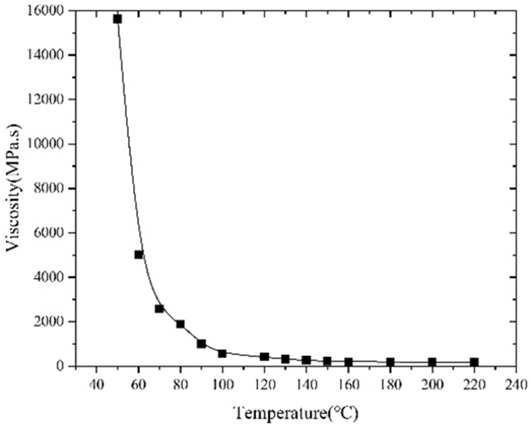
The viscosity–temperature curve for the oil sample used in this work.
Apparatus
A large-scale 3D physical model is used to evaluate the production performance of every process. Figure 2(a) shows the large-scaled 3D simulation experiment device, which consists of five parts: oil sand mixing system, injection system, large-scaled simulation model, output system, and control record system.
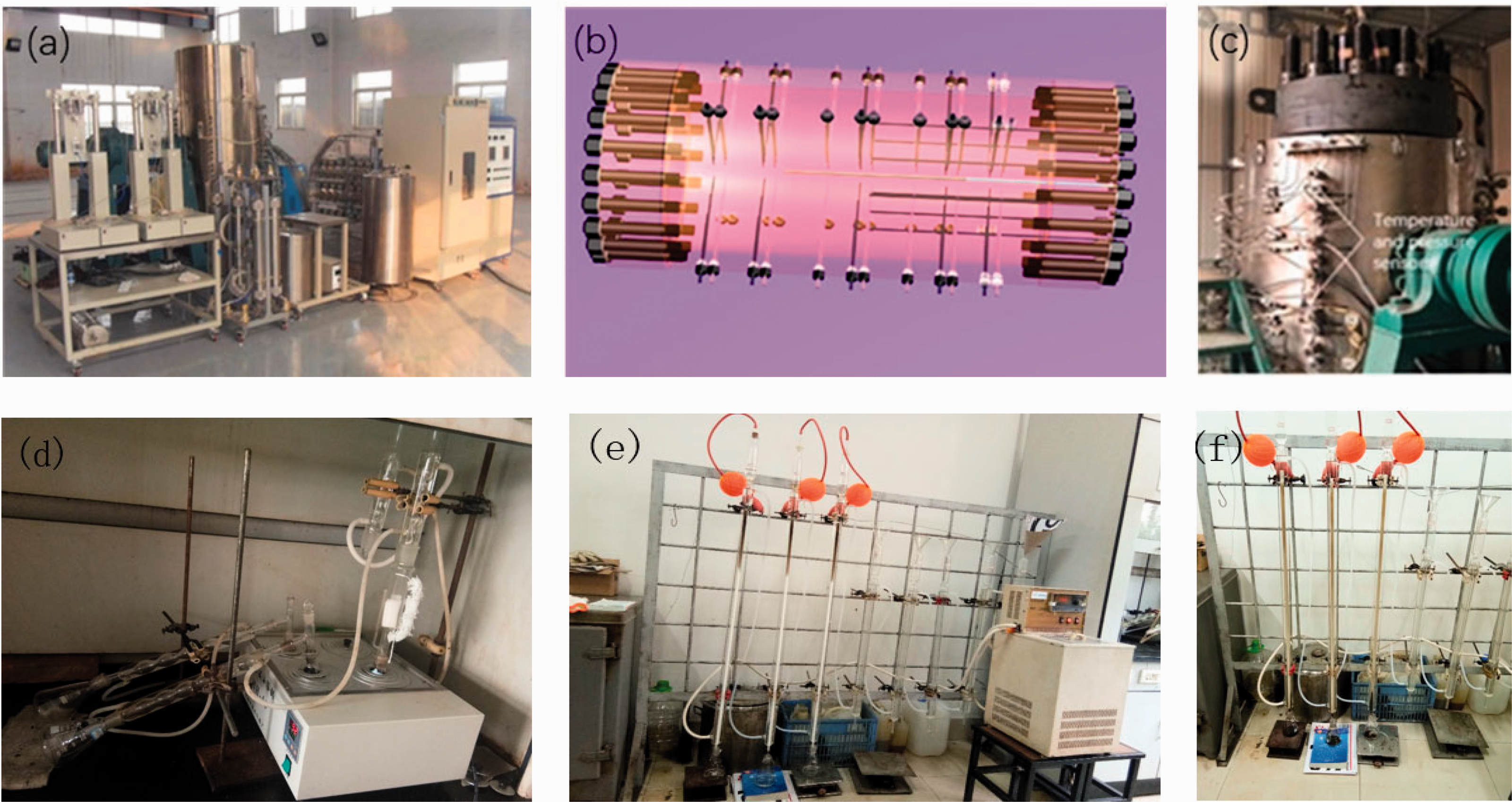
System of this simulation experiment. (a) The large-scale 3D simulation experiment device. (b) Schematic diagram of internal structure. (c) External structure of the model. (d), (e) and (f) Asphaltene measuring equipment.
The oil sand mixing system was comprised of an oil-sand mixing agitator and thermostat. The injection system consisted of ISCO high-precision plunger pump (the 100DX from Teledyne ISCO Company, Teledyne Co., Ltd., Thousand Oaks, CA, USA; flow accuracy ± 0.25 µL/min, and pressure accuracy ± 0.5%), steam generator (from Fei Yu Technology Co. LTD, with a temperature range of 450°C and pressure range of 25 MPa), pressure gauge, check valve, cylinder, intermediate container and gas flow controller (Sla58550, with a flow rate range of 30 mL/min under standard conditions; Brooks, USA), which can inject oil, water, steam, and flue gas into the model. The large-scale simulation model was a cylindrical structure, the inner space of this model was 50 cm × 100cm, and its volume was 196.35 L, and the maximum operating temperature and pressure of this model were up to 350°C and 50 MPa respectively. A total of 180 temperature sensors in 36 groups were uniformly distributed in the simulated chamber, as shown in Figure 2(b) and (c), then connected the computer to record the change of temperature inside the model at each time. Fourteen wells were distributed at the front end of the model and one well at the back-end center. The front and rear ends were equipped with a detachable insulation layer. The output system was aimed to collect and measure the output oil-water. Computer, temperature sensors, and pressure sensors were constituted a control recording system to collect and process temperature data in each production stage.
Figure 2(d), (e), and (f) show the asphaltene measuring equipment to measure the component of heavy oil.
Experimental parameters and procedures
Experimental parameters
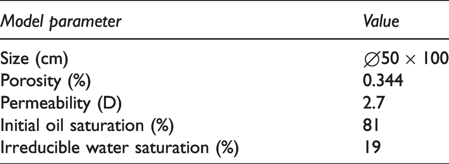
Table 1 shows the parameters of this experiment. The porosity and permeability of the simulated reservoir were 0.34, 2.7D respectively. The original oil saturation was 81%, and the bound water saturation was 19%. In terms of a certain mass ratio, silica sands of 80–120 mesh in a ratio of 10:5:3, water, and oil with 10.6% water cut were mixed. The mass of oil, sands, and water in the mixture was 55.69 kg, 338.41 kg, and 5.96 kg respectively. Due to the interference of air during the filling process and the presence of part of pore volume in the sand, after the filling of oil sand, continued to inject a mixture of oil-water proportionally, and 4.3 L of the oil-water mixture was injected.
Parameters of large-scaled simulation model.
Experimental procedures
(1) Selection of experimental wellhead
In this experiment, two horizontal wells were used to produce in this experiment, as shown in Figure 3, boreholes A as an injection well and B as a producing well, well A was above well B. Due to the spacing between two wells in the practical oil field was 10 m, the well distance of wells A and B was set as 20 cm according to the ratio between reality and model was 50:1, which both stood 10 cm apart from the center of the model. In this case, the development boundary of the temperature field and flow field had less effect on the model that surrounding temperature measurement points were more concentrated. It was aimed to prevent oil sand from blocking the simulated well by wrapping a sand prevention meshwork of 400 mesh around the simulated well before inserting wells into the model.
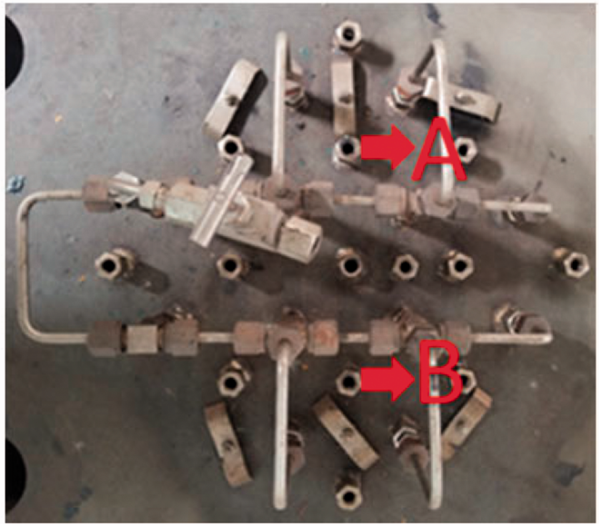
Position of simulated well.
(2) Process of filling oil and sands
This physical simulation experiment was different from the conventional method that sand filling followed by saturated oil, which called a dry filling. In this experiment, an innovative method called wet filling was adopted, that was, oil and sands were mixed before filling. The method of dry filling has difficulties in heavy oil injection and uneven mixing of oil sands, which greatly impacts the experimental results. However, the way of wet filling solved the problem of uneven mixing of oil sands, and the correctness and objectivity of ultimate results were ensured well.
After filling oil and sands, sand prevention meshwork was set at both ends of the model to prevent oil sand from polluting this model. The 3d large-scale simulation model was put laterally for overall heating. The initial temperature was set at 50°C, and checked the temperature, pressure sensors at the same time.
(3) Design of scheme
Figure 4(a) and (b) provide flow diagrams of this experiment, three stages are designed to compare. Steam huff and puff was performed first, and the following was SAGD. Finally, flue gas and steam were injected simultaneously, transferring to the production of flue gas assisted SAGD. The design of the three stages has been shown below:
Process of steam huff and puff: This production was aimed to preheat the reservoir between wells A and B. The temperature of steam injected into wells A and B was 350°C. The total amount of steam injected was 2000 mL, the steam injection rate of each well was 10 mL/min and the injection time was 100 min. Then opening wells for oil production after soaking 100 min, measuring the output of oil and water. Finally, steam huff-and-puff production lasted for six cycles to form initial thermal connectivity between two wells. Process of SAGD: At this stage, well A was set as an injection well and well B was a production well. The temperature of steam injected into wells A at a rate of 20 mL/min was still 350°C, which lasted for 4000 min. Measuring the oil-water output of well B regularly. Process of flue gas assisted SAGD: In this stage, the injection well and production well were unchanged. Different from the SAGD, steam and flue gas were injected simultaneously, injection temperature were all 350°C; the flue gas injection rate was 4 mL/min and the steam injection rate was 16 mL/min. Measuring the oil-water output of well B regularly.
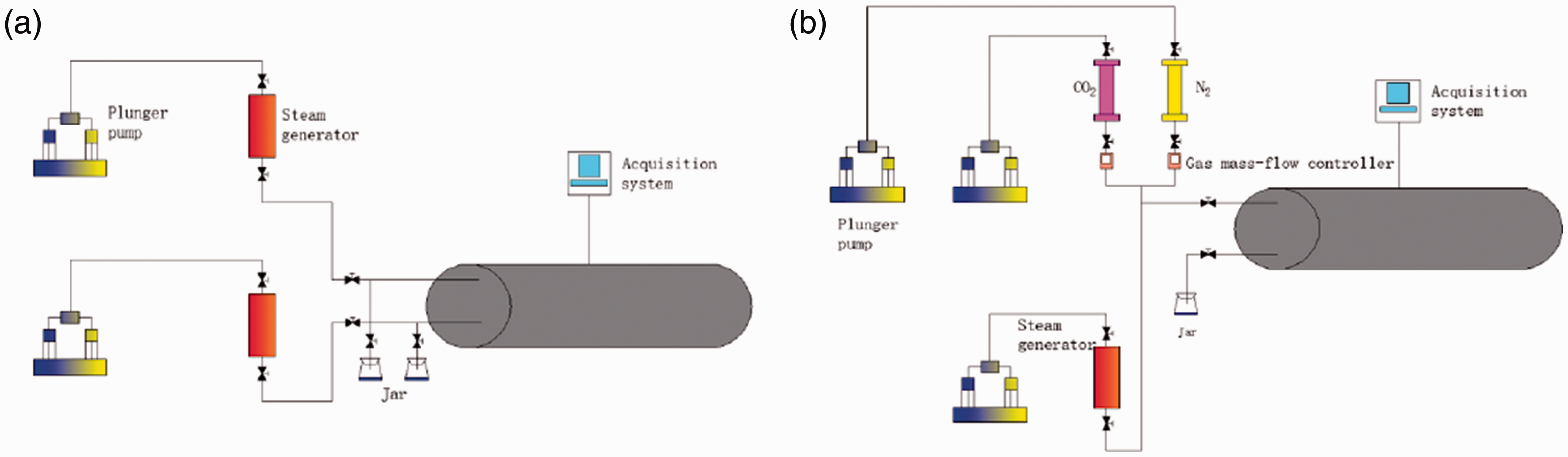
Flow chart of this work. (a) Flow diagram of steam huff and puff. (b) Flow diagram of SAGD or flue gas assisted SAGD.
Meanwhile, thermocouple temperature measuring sensors were used to monitor and record temperature change in three production processes. The specific injection parameters of the three stages are shown in Table 2.
Injection parameters.
SAGD: steam assisted gravity drainage.
(4) Heavy oil composition measurement
To measure the four components of heavy oil, according to the relevant provisions of the petrochemical industry standards of the People's Republic of China, asphaltene was precipitated out of the sample with n-heptane. After filtration, n-heptane reflux was used to remove the soluble part contained in the precipitation, and toluene was used again. The fluid dissolves and precipitates to obtain asphaltenes. Then, the diasphaltene was adsorbed on the column of alumina chromatography, and washed out with n-heptane toluene and toluene – ethanol successively, corresponding to the saturate, aromatic and resin fraction.
Results and discussions
The experimental results were divided into three aspects to analyze, including the production of oil-water at each stage, changes of temperature field, and components of produced oil.
Analysis of oil and water output
Steam huff and puff stage
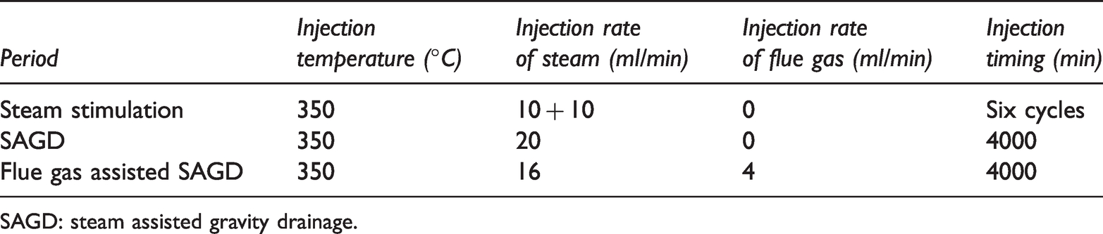
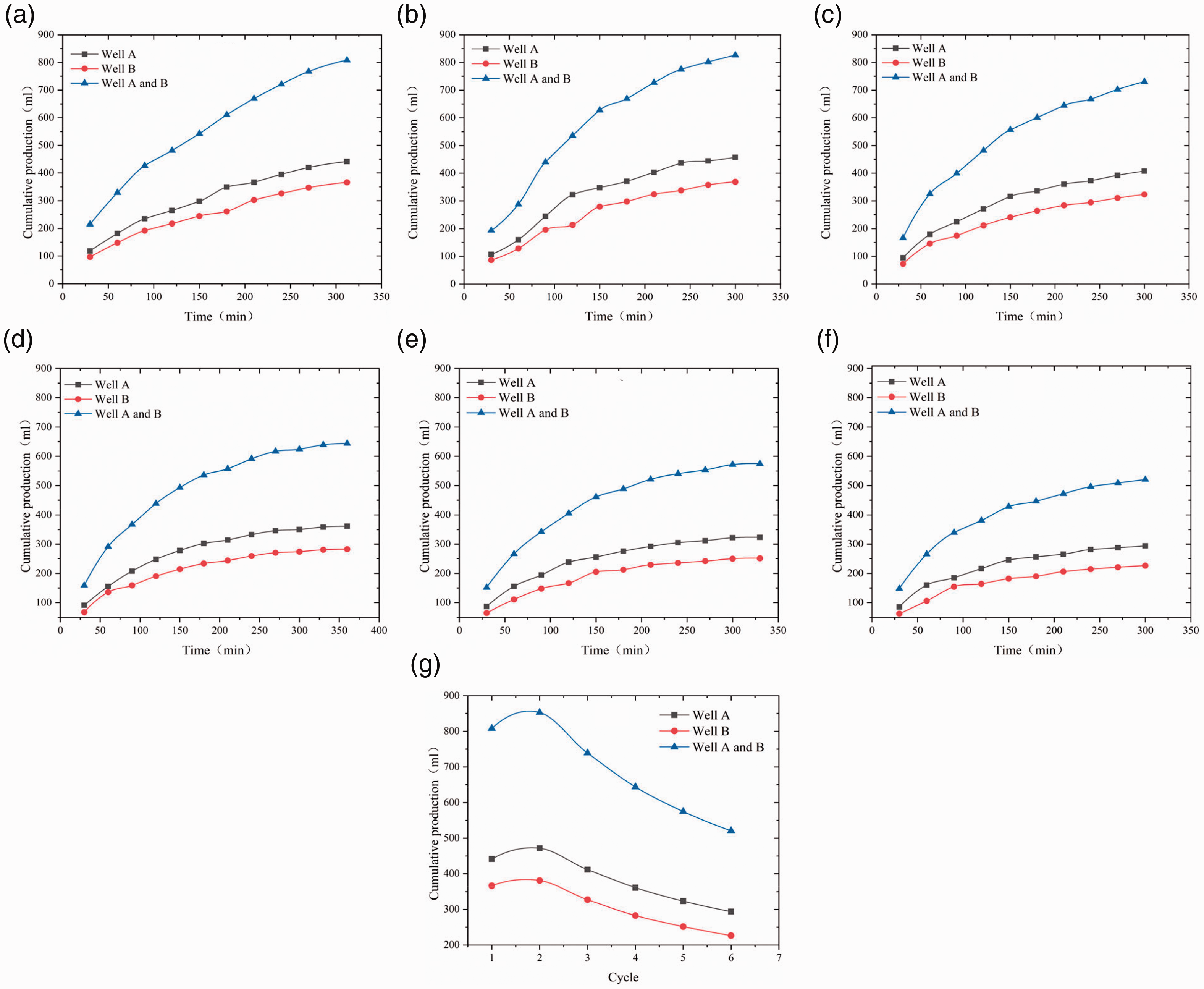
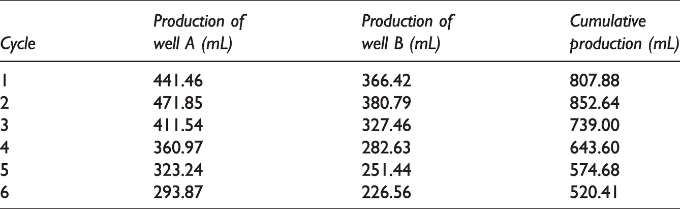
Steam huff and puff lasted for six cycles. The cumulative oil production was 4,138.21 mL. Figure 5(a) to (g) and Figure 6(a) to (g) respectively show the performance of oil production and water cut of two wells in six cycles, and the output data was listed in Tables 4 and 5.
Changes of oil production with time in different cycles. (a) The first cycle. (b) The second cycle. (c) The third cycle. (d) The fourth cycle. (e) The fifth cycle. (f) The sixth cycle. (g) Cumulative oil production.
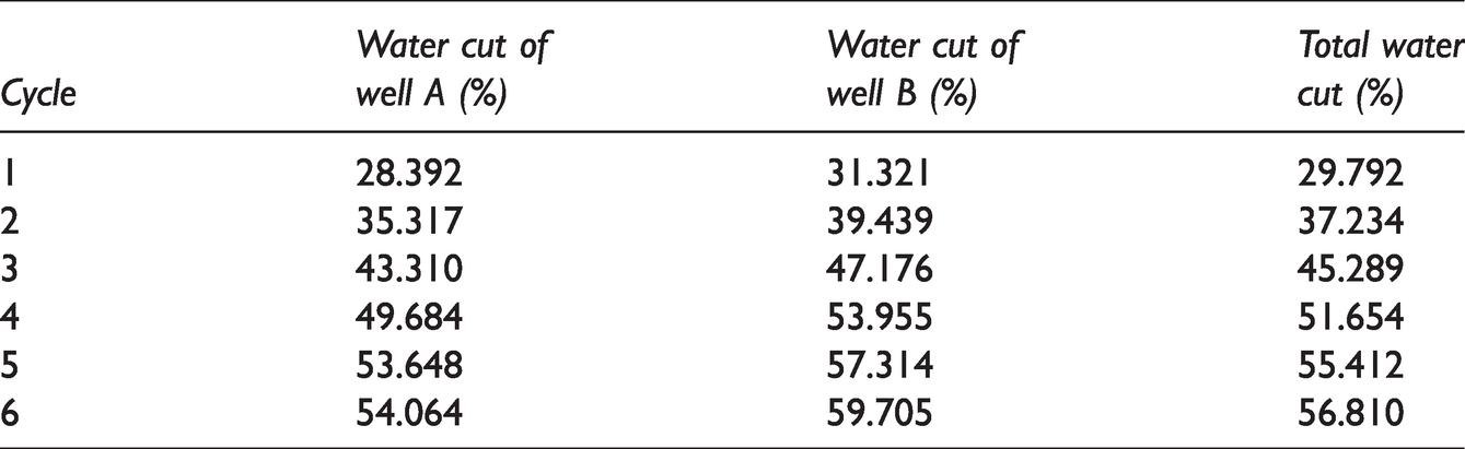
Changes of water cut with time in different cycles. (a) The first cycle. (b) The second cycle. (c) The third cycle. (d) The fourth cycle. (e) The fifth cycle. (f) The sixth cycle. (g) Water cut at the end of each cycle.
Water cut in six cycles of steam huff and puff.
Sample component ratio.
SAGD: steam assisted gravity drainage.
It can be seen from Figure 5 and Table 3 that oil production was higher in the early stage, especially in the second cycle, which lasted for 300 min, with cumulative oil production was 852.63 ml. The injection of steam reduced the viscosity of heavy oil and enhanced the utilization of natural energy in the reservoir (Ebadati et al., 2019), so the initial production was relatively high. From 2nd to 6th cycle, cumulative oil production gradually decreased by 218.59 ml. With the increase of steam huff and puff rounds, the reservoir energy will be decreased gradually, resulting in the oil production will be reduced. The variation trend of oil production in six cycles was similar, and the oil production of well B was higher than that of well A. Analysis suggested that steam overlapped upwards because of its lower density, causing that the reservoir near the upper acquired more heat and the oil viscosity was reduced greatly according to viscosity-temperature characteristics, making the heavy oil fluidity of upper well become better and flowing to the well B under action of gravity, so the oil production of well B was higher than well A.
Oil production in six cycles of steam huff and puff.
As shown in Figure 6 and Table 4, the water cut increased gradually after cyclic steam stimulation, from fourth cycle to sixth cycle, the water cut maintained above 50%, the internal energy of the model was lost, weakening the effect of oil displacement. At the beginning of each production cycle the water cut of the upper and bottom wells decreased rapidly, but the change of water cut with time in every production round was not obvious. Analysis considered that steam overlapped to exchange heat with porous media (oil-sand), which lost heat and condensed into water. The condensed water was produced rapidly because of it has high relative permeability when opened wells for production. Therefore, the water cut was relatively high in the early stage. With the rapid output of condensed water at early stage, water cut gradually decreased and tended to be stable. Condensate water from the well A flowed into the well B by the gravity, which accelerated the condensation rate of steam injected into the well B, so the water cut of the upper well (well A) was lower than that of the bottom well (well B).
Comparison of production performance of SAGD stage and flue gas assisted SAGD stage
The process of SAGD production lasted for 4000 min and its cumulative oil production was 5495.95 ml, after adding flue gas, the production time was prolonged 4000 min, with cumulative oil production was 3,143.07 mL. Figure 7(a) to (d). provides production performance of two stages, including oil production rate, cumulative oil production, water cut, and cumulative oil-steam ratio respectively.
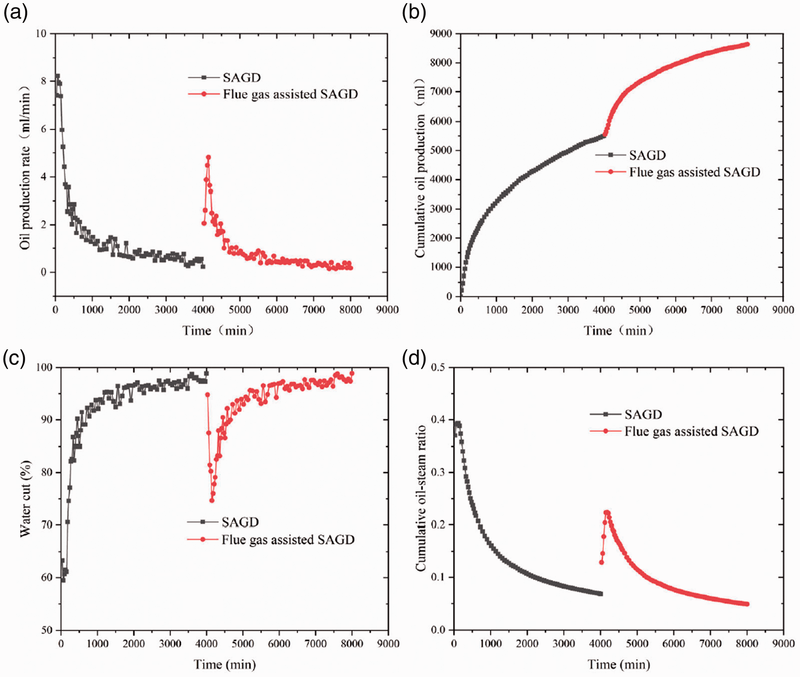
Comparison of production performance of SAGD stage and flue gas assisted SAGD stage. (a) Oil production rate. (b) Cumulative oil production. (c) Water cut. (d) Cumulative oil-steam ratio.
In SAGD experiment, from 0 min to 600 min, this period was a fast drainage stage, the oil production rate was relatively high due to the dual effects of steam displacement and gravity drainage, with the highest reached 8.24 mL/min. The cumulative oil production increased rapidly, the cumulative oil-steam ratio reached the highest 0.39 at this time, owing to the steam chamber had been taken shape and had a rapid expansion rate. From 600 min to 1900 min, the oil production rate gradually slowed down, and the cumulative oil-steam ratio declined continually, water cut gradually increased to 90%, indicating that the steam chamber development was stable. Beginning from 1900 min, the oil production rate was very low, with around about 0.4 ml/min, and the cumulative oil-steam ratio decreased to 0.068, indicating that steam chamber development basically stagnated. The steam overlapped at the top of the model and lost heat outward, there was no enough time to diffuse and release sufficient heat laterally and condensed into quickly, therefore, water cut was maintained at above 95%.
After adding flue gas, from 4000 min to 4600 min, which was as the high-speed oil drainage stage, the oil production rate recovered to 4.83 mL/min in a short time, water cut decreased to 74% and the oil-steam ratio showed a trend of gradual rise, indicating that the production effect of SAGD was improved obviously. That is because that flue gas first fingered (Wang et al., 2019a), which reduced the seepage resistance and accelerate steam expansion rate, steam heat exchange with the reservoir was more sufficient. This period could be regarded as a re-development stage when the oil production recovered at a relatively high level (Li et al., 2019). Form 4600 min to 6000 min, the oil production rate continued to decline, which was in a stable oil drainage period as well, the water cut increased gradually. At 8000 min, oil production rate was very low and the water cut was extremely high due to the arrested development of steam chamber.
Figure 8 shows that foam oil produced after injecting flue gas, the foam mainly come from the light components dissolved in heavy oil which become gas-phase under high temperature (Wu et al., 2018), which indicated that flue gas was slightly more effective in viscosity reduction and swelling for remaining oil (Dong and Huang, 2002; Ebadati et al., 2019). Under the combination of steam and flue gas, interfacial tension and viscosity of heavy oil were decreased, the fluidity of heavy oil was increased, and drainage becomes better. The lateral sweep area of steam was broadened, improving oil displacement efficiency significantly, thus recovery factor was enhanced finally. Compared with SAGD, the oil recovery in flue gas assisted SAGD experiment was improved by about 5.7%, this experimental result certified that flue gas possessed abilities that could observably prolong production time and decrease water cut, improving the development effect of SAGD.
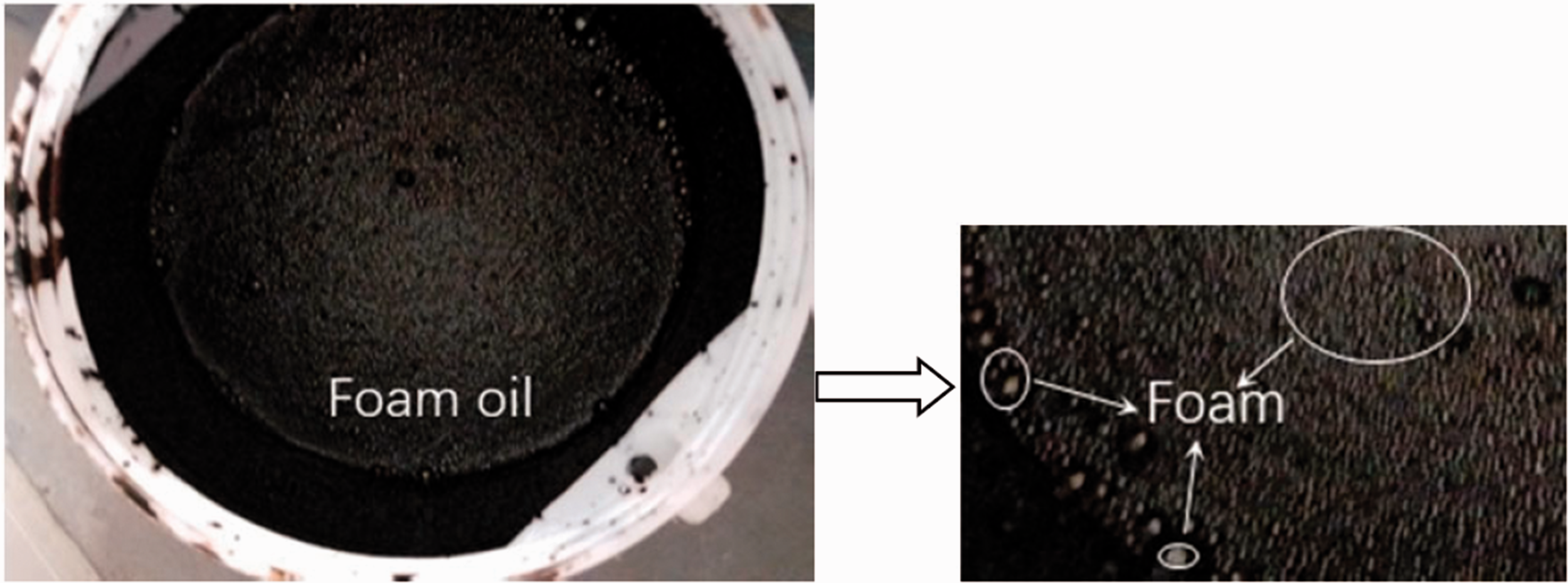
Foam oil produced during flue gas assisted SAGD stage.
Analysis of temperature distribution
Steam huff and puff stage
Figure 9(a) and (b) show the images for the temperature distribution profile along with wells and perpendicular to wells at different huff and puff cycles. By analyzing the temperature field at the end of each cycle, the high temperature area mainly concentrated along the well, as shown in Figure 9(a), however, the temperature distribution along the horizontal well was uneven. In addition, the steam condensate and heavy oil flowed into well B under the influence of gravity, resulting in the steam of the bottom well lost more heat and the high-temperature area near well B was smaller than that near well A, as shown in Figure 9(a1) and (b1). After the second cycle, the temperature between the two horizontal wells began to rise, as shown in Figure 9(a2). The initial thermal interconnecting between wells had been formed by steam huff and puff experiment, with the temperature between two wells increased by nearly 20°C, as shown in Figure 9(a3) and (b2). However, after several rounds of huff and puff, the steam sweep area was still limited, which resulted in the oil production declined.
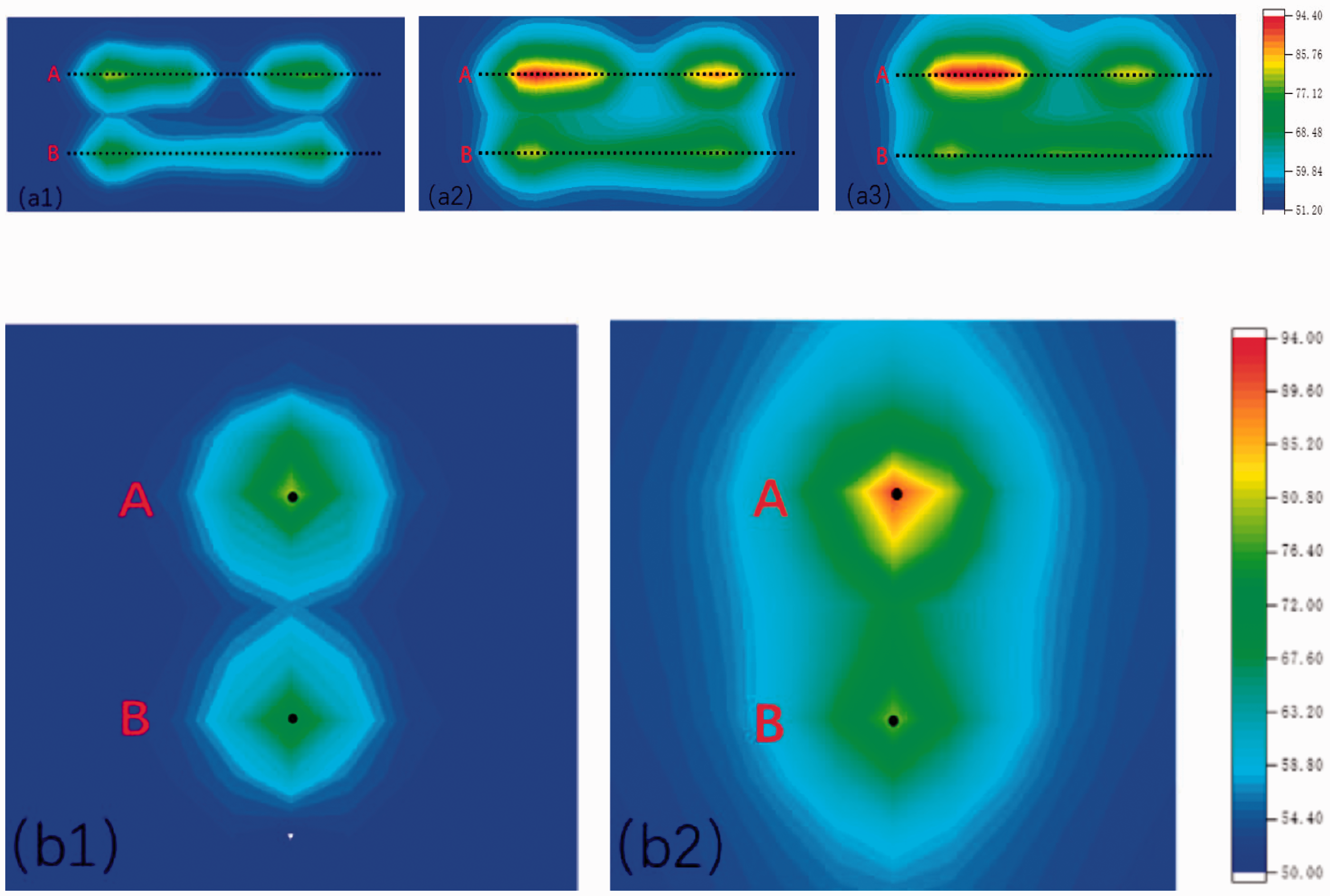
Changes of temperature field in the steam huff and puff experiment. (a) Profiles of temperature distribution along wells. (a1) The end of second cycle. (a2) The end of fourth cycle. (a3) The end of sixth cycle. (b) Profiles of temperature field perpendicular to wells. (b1) The end of the second cycle. (b2) The end of the sixth cycle.
SAGD stage
Figure 10(a) and (b) respectively shows the images for the temperature distribution of SAGD process along with wells and perpendicular to wells at different times.
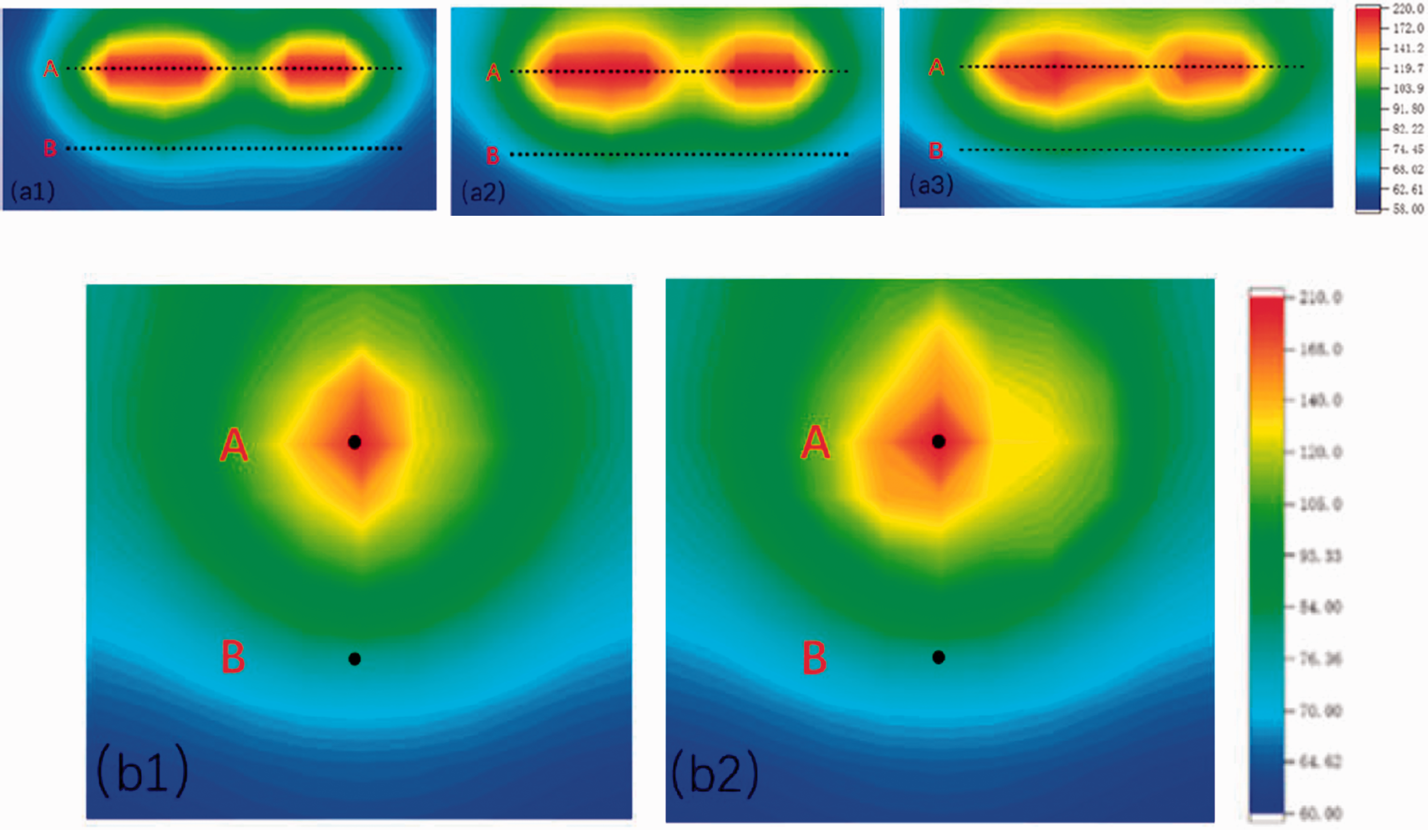
Changes of temperature field in the SAGD experiment. (a) Profiles of temperature distribution along wells. (a1) 600 min. (a2) 1900 min. (a3) 4000 min. (b) Profiles of temperature field perpendicular to wells. (b1) 600 min. (b2) 4000 min.
Compared with steam huff and puff, the temperature of SAGD at 600 min had gone up significantly in Figure 10 (a1), with the highest temperature was up to about 220°C, and sweep area of steam near the injection well had increased obviously, indicating that the steam chamber expanded rapidly. What’s more, due to the viscosity of heavy oil was extremely sensitive to temperature, when the temperature rises, the viscosity was decreased substantially and the fluidity was enhanced, so the oil production rate was fast in this period. In addition, heavy oil with the condensate steam flowed along with the vapor-liquid contact toward the production well and formed large pores, so the high-temperature part gradually developed towards the lower part of the model, as shown in Figure 10(b1), the steam chamber had a high longitudinal expansion rate. Figure 10(a2) shows that steam also gradually expanded along the horizontal well to heat heavy oil when it overlapped. From 600 min to 1900 min, the steam gradually began to overlap the top of the model, although the upward development speed of the steam chamber decreased, the area of high temperature area increased further this period was in the stable gravity drainage stage.
However, from 1900 to 4000 min, the steam lost heat outward when it gathered at the top of the model, the injected steam could not extend sufficiently and condense into water quickly, thus the steam chamber basically no longer developed upward and the lateral expansion rate was extremely low, as shown in the Figure 10(a3) and (b2). For another thing, the lateral migration of steam in the model was also limited, which resulted in the oil production rate declined by a big margin and the water cut was high with escalating rate. The main reason for entering the depletion stage in SAGD was that steam lost heat outward when it overlapped to the top and water cut was increased, leading to the lateral development of the steam chamber was insufficient.
Flue gas assisted SAGD stage
Figure 11(a) and (b) respectively show the images for the temperature distribution of flue gas assisted SAGD process along with wells and perpendicular to wells at different times.
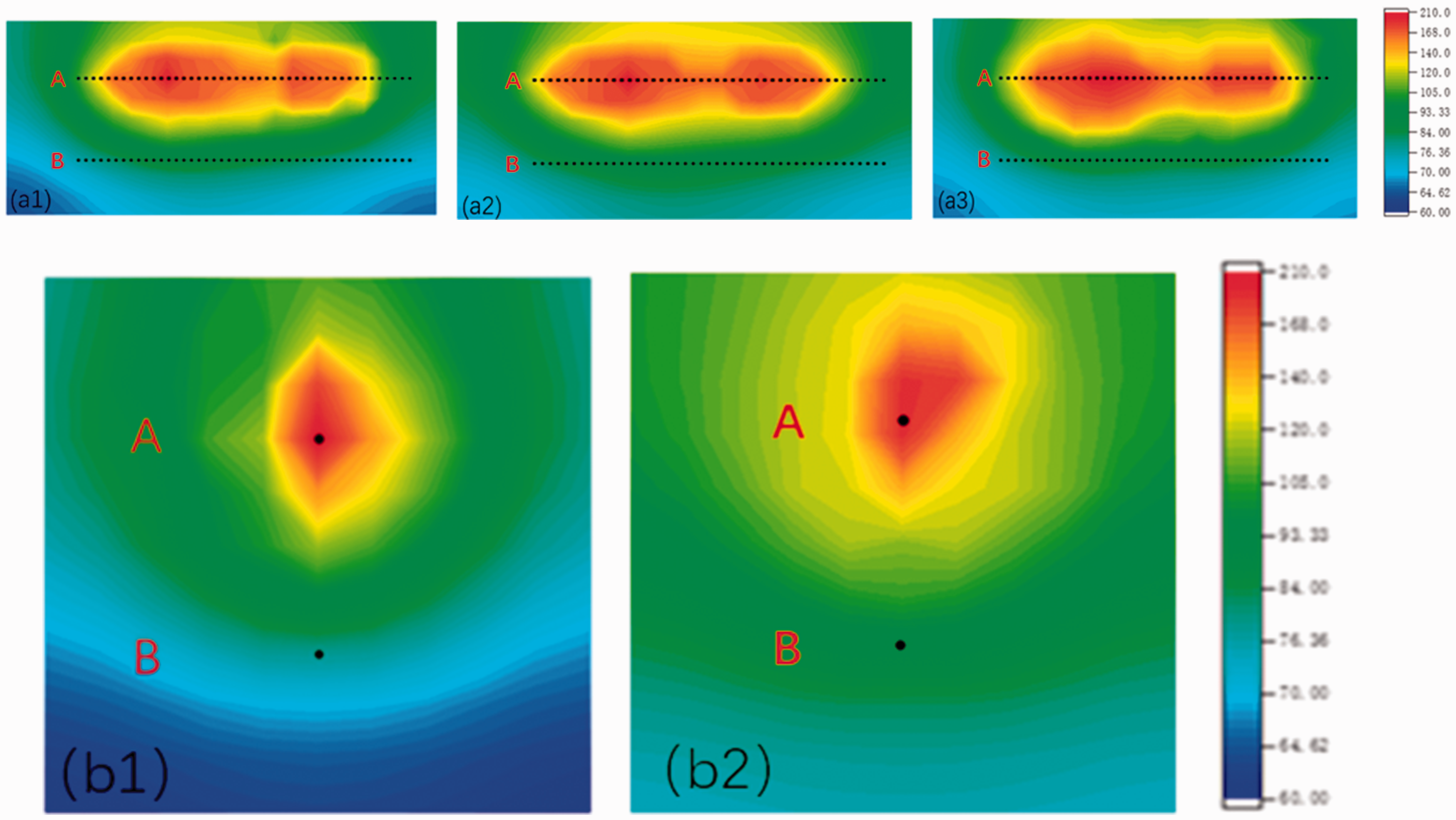
Changes of temperature field in the flue gas assisted SAGD experiment. (a) Profiles of temperature distribution along wells. (a1) 4600 min (a2) 6000 min. (a3) 8000 min. (b) Profiles of temperature field perpendicular to wells. (b1) 4600 min. (b2) 8000 min.
From 4000 min to 4600 min, due to the flue gas had relatively low density and weak heat-transfer capability, and can firstly enter along the pore, reducing the seepage resistance of steam, the loss of steam along the way was also decreased and the heat exchange with the reservoir was more sufficient (Chen et al., 2020). Furthermore, nitrogen density was relatively low, which resulted in the diffusion coefficient was high, and the interfacial tension between nitrogen and heavy oil was small (Yuan et al., 2018), therefore, nitrogen readily expands longitudinally, the steam chamber was developed laterally again. The swept zone and saturation temperature zone encroached to the sides gradually, as shown in Figure 11(a1) and (b1). Conventional SAGD technique merely uses gravity drainage from natural drive mechanisms, while flue gas-assisted SAGD effectively utilizes nitrogen to replenish reservoir energy and form a thermal barrier at the top, and makes use of carbon dioxide that can diffuse and dissolve into the oil (Davarpanah and Mirshekari, 2019), which is a good combination of gravity drive, gas cap drive, and solution drive (Davarpanah and Mirshekari, 2018).
From 4600 min to 600 min, flue gas had accumulated at the top of the model to play a critical role in preventing heat loss, improving the heat utilization rate of steam, and forcing steam to migrate to both sides (Fatemi, 2010; Gao et al., 2009). As shown in Figure 11(a2), flue gas gathering at the top tended to drive steam expands laterally, which promoted the re-development of the steam chamber laterally, which resulted in the horizontal sweep of steam was extended and the area of the hot zone was further enlarged. At 8000 min, the steam chamber basically no longer expanded, compared with SAGD stage, the final degree of oil production along the horizontal well section was further increased, as shown in Figure 11(a3). Furthermore, flue gas had the property of non-condensate gas, what can be known from Dalton's partial pressure law that the flue gas would reduce the partial pressure of steam (Li et al., 2019), the steam pressure that maintained the steam chamber development was decreased, therefore, the temperature inside this model decreased by about 10°C.
Combined with the previous oil production performance and temperature distribution, it was obvious that the steam chamber developed laterally again by injecting flue gas, and the oil drainage effect was improved, which effectively prolonged the production time of SAGD and enhanced oil recovery factor.
Through this 3D experimental investigation, it could be concluded that steam huff and puff preheating effectively formed a thermal connection between two wells and provided a good foundation for subsequent SAGD. In addition, by comparing three development methods, steam huff and puff could not fully utilize the heat of steam, and the steam extension range was greatly limited. The existence of a steam chamber allowed the steam to expand fully to enhance oil recovery factor obviously in process of SAGD, however, the steam heat loss seriously affected the development effect of SAGD. The flue gas injection not only reduced steam heat loss and water cut to promote the steam chamber lateral re-development, but also increased the degree of reservoir exploitation around the horizontal wells.
Component analysis of produced oil
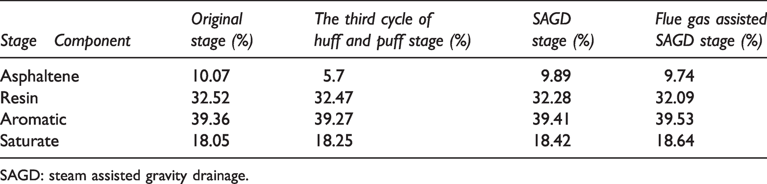
To study the change of oil composition in different stages, a total of 13 groups of samples were measured at different times by asphaltene measuring equipment. Four representative groups were selected for component analysis to determine the proportion of asphaltic, resin, aromatic, and saturate contents. Changes in component content are shown in Table 5.
According to Table 5, the content of aromatic was the highest, followed by was resin and saturate, and the content of asphaltene was the lowest, among which the content of light component aromatic was more than 39% and that of heavy component resin than more than 32%. There was a tendency that the content of heavy components (resin and asphaltene) decreased gradually at each stage of heavy oil production, while the content of light components (saturate and aromatic) increased.
The analysis suggested that the temperature of the reservoir gradually increased to reduce the viscosity of heavy oil, during steam huff and puff and SAGD stage, the light components (saturated and aromatic) in heavy oil had smaller viscosity and stronger flow capacity, which were more easily produced. Therefore, not only the content of light components was increased, but also the content of heavy components was decreased. Meanwhile, the temperature in the steam huff and puff stage was lower than that in the SAGD stage, and the fluidity of the light component in heavy oil was relatively weak, so the content of light components in the steam huff and puff stage was lower than that in SAGD stage. The steam chamber was promoted and the remaining oil was heated adequately in the process of flue gas assisted SAGD production. The density of heavy oil was decreased by injecting CO2 in high pressure and high temperature. CO2 could diffuse and dissolve in the oil layer with steam, reducing the viscosity of heavy oil (Davarpanah and Mirshekari, 2020; Hu et al., 2020), making the cementation recombine into a dispersed phase, and extraction of the light components by CO2 was gradually enhanced (Wang et al., 2020), so that more light components were produced and the heavy components were reduced.
Conclusion
Based on the 3D large scaled physical experimental study of flue gas assisted SAGD, the following conclusions can be drawn:
As a new technology, flue gas assisted SAGD has a promising application prospect. The 3D large scaled physical experiment was successfully performed in this paper, the results indicate that flue gas injection prolongs production time effectively and restricts increase of water cut, significantly improving the performance of SAGD. The final recovery is improved by about 5.7% after injecting flue gas. Steam huff and puff preheating effectively forms a thermal connection between two wells; the steam swept area is limited because of heat loss in the period of SAGD and heating along horizontal wells are uneven especially; Flue gas can gather at the top of model to reduce steam heat loss and drive steam extend laterally, not only promoting the steam chamber lateral development, but also increasing the degree of reservoir exploitation around the horizontal wells, and the thermal utilization of steam is improved effectively. The addition of flue gas in SAGD can product foam oil because of carbon dioxide dissolution, and can further reduce heavy components of heavy oil (Resin and Aromatic), improving flow property of heavy oil.
Footnotes
Acknowledgements
The authors would like to thank the editors and anonymous referees for their valuable comments and suggestions.
Declaration of conflicting interests
The author(s) declared no potential conflicts of interest with respect to the research, authorship, and/or publication of this article.
Funding
The author(s) disclosed receipt of the following financial support for the research, authorship, and/or publication of this article: The research was supported by the Jiangsu Industry-University-Research Cooperation Project for study on cold recovery and stimulation technology of non-hydrocarbon gas (N2/CO2) heavy oil with multi-effect chemical agent (NO.BY2019068) and the Province Key Scientific and Technological Project for the camellia saponin extraction and CO2 saponin foam with highly mineralize of China (No. KYCX20_2577).