
Abstract
During horizontal well staged fracturing, there is stress interference between multiple transverse fractures in the same perforation cluster. Theoretical analysis and numerical calculation methods are applied in this study. We analysed the mechanism of induced stress interference in a single fracture under different fracture spacings and principal stress ratios. We also investigated the hydraulic fracture morphology and synchronous expansion process under different fracture spacings and principal stress ratios. The results show that the essence of induced stress is the stress increment in the area around the hydraulic fracture. Induced stress had a dual role in the fracturing process. It created favourable ground stress conditions for the diversion of hydraulic fractures and the formation of complex fracture network systems, inhibited fracture expansion in local areas, stopped hydraulic fractures, and prevented the formation of effective fractures. The curves of the maximum principal stress, minimum principal stress, and induced principal stress difference with distance under different fracture lengths, different fracture spacings, and different principal stress ratios were consistent overall. With a small fracture spacing and a small principal stress ratio, intermediate hydraulic fractures were difficult to initiate or arrest soon after initiation, fractures did not expand easily, and the expansion speed of lateral hydraulic fractures was fast. Moreover, with a smaller fracture spacing and a smaller principal stress ratio, hydraulic fractures were more prone to steering, and even new fractures were produced in the minimum principal stress direction, which was beneficial to the fracture network communication in the reservoir. When the local stress and fracture spacing were appropriate, the intermediate fracture could expand normally, which could effectively increase the reservoir permeability.
Introduction
Horizontal well drilling and staged fracturing technologies have become important in developing unconventional shale and tight sandstone reservoirs (Guo et al., 2020; Li et al., 2018b, 2018c; Wang et al., 2019b). Multi-access perforation and staged fracturing in horizontal wells produce a large number of cross-cut fractures, increase the fracture area, fully connect the reservoir, and improve reservoir permeability (Escobar et al., 2019; Liu et al., 2020; Ma et al., 2020; Zeng and Yao, 2020). When developing unconventional oil and gas reservoirs by staged horizontal well fracturing, there are multiple perforation clusters in each fracturing section and stress interference between multiple cross-cut fractures. This phenomenon is called the “stress shadow” effect (Zhou et al., 2018). Stress interference can not only affect fracture geometry, but also the geometry of other hydraulic fractures in the adjacent area. This leads to the smaller adjacent fracture hydraulic fracture width, the increase in bending degree, and premature sand removal, which restricts proppant spreading and mesh fracture formation (He et al., 2017; Yoon et al., 2015; Zangeneh et al., 2015; Zhou et al., 2017). Therefore, a full understanding of the stress interference between multiple parallel fractures can help to optimize the fracturing section spacing and perforation spacing during the completion design phase.
Scholars have researched stress interference induced by multiple fractures (Dong et al., 2019; Wang et al., 2018; Xia and Zeng, 2018). The fracture tip stress interference was first proposed by Green et al. and Sneddon et al. (Green and Sneddon, 1950; Sneddon and Elliot, 1946). Warpinski et al. used the analytical method to deduce a formula for single fracture-induced stress under internal water pressure, which laid a foundation for subsequent research on induced stress interference between fractures (Warpinski and Teufel, 1987). Jonathan et al. simulated the stress shadow by using a finite element model and studied the influence of the horizontal in situ stress ratio, Poisson′s ratio, Biot parameters, and net fracture internal pressure on fracture spacing (Jonathan and Jennifer, 2012). The greater the stress anisotropy is, the smaller the fracture steering trend caused by stress interference (Hyunil, 2012). By using dimensional analysis, Bunger and others have studied the propagation pattern of hydraulic fractures under stress interference and pointed out that post-fracturing fractures communicate or stay away from fractures that have been fractured (Bunger et al., 2012). Sobhaniaragh et al. shed light on the stress shadowing effect on conventional completion designs, namely simultaneous HF (Sim-HF) and Sequential HF (Seq-HF) with the help of the Texas two-step method (TTSM) (Sobhaniaragh et al., 2019). The stress interference between simultaneously grown hydraulic fracturing and how they propagate transversely and longitudinally under evolving in-situ stress conditions is thoroughly discussed (Guo et al., 2019a, 2019b). Increasing fracture spacing can reduce stress interference and avoid post-fracturing fractures penetrating into fracturing hydraulic fractures (Nicolas and Mukul, 2010; Peng, 2020; Soliman et al., 2008).
In the multi-branch horizontal well fracturing process, stress interference affects fracture length, width, height, and expansion direction. Based on the extended finite element method (XFEM), Gutierrez et al. studied the stress interference between fractures during the staged fracturing process of the layered formation (Escobar et al., 2019). Wang et al. analysed the stress interference between existing natural fractures and extended fractures during temporary staged fracturing plugging (Wang et al., 2019a). Paul further proposed a HM-XFEM solid-hydraulic coupling method to study stress interference between adjacent induced fractures under complex stress conditions (Paul et al., 2018). However, due to the HM-XFEM coupling model complexity, it could only simulate a small number of induced fractures. Based on stress interference and induced stress distribution between multi-cluster fractures, Guo et al., Lin et al., Zhao et al., and Ripudaman et al. proposed optimizing the perforating cluster number, distance, injection speed, permeability and heterogeneity to reduce the stress interference between induced fractures during hydraulic fracturing (Guo et al., 2015; Lin et al., 2017; Manchanda et al., 2016; Zhao et al., 2017). It is also shown by the research that pore pressure and stress interference have significant effects on fracture geometry and migration. For example, the increase in pore pressure between fractures affects fracture geometry and makes fracture width and length narrower and shorter (Saberhosseini et al., 2019). As a result of stress inter-fracture interference, heterogeneity of stress and material properties, well inclinations, and formation dip, cluster fractures cannot form an ideal symmetrical shape on the well (Ren et al., 2019). Past work has shown that existing methods and models have some advantages and disadvantages. Thus, it is important to study the mechanism of stress interference between parallel multi-fractures and hydraulic fracture expansion.
This study analysed the induced stress field of multiple parallel fractures under different fracture lengths and spacing conditions. We used induced stress calculations for single fracture and multiple fractures and RFPA2D-Flow software to compare the hydraulic fracture morphology with different fracture spacing and principal stress ratios. We also analysed the hydraulic fracture expansion process. This study offers a deeper understanding of the induced stress disturbance mechanism between parallel multi-fractures, which can provide some reference for multi-cluster fracturing design and construction parameters.
Induced stress interference mechanism of single and multiple fractures
Induced stress interference mechanism of single fracture
When a single straight fracture is subjected to hydraulic pressure, the fracture opens and produces a stress field on the surrounding rock medium. According to Sneddon et al. and Warpinski et al., elastic mechanics analytical solution and analytical expression of the stress field of the vertical fracture under a compressive stress state surrounding rock can be calculated by the equation (1), which are as follows (Sneddon and Elliot, 1946; Warpinski and Teufel, 1987).
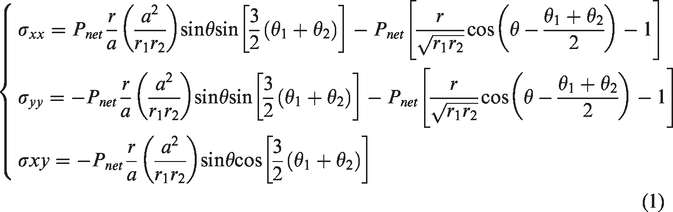
Induced stress field generated by water pressure in the fracture. (a) Two-dimensional fracture signal. (b) Induced stress field △σxx/Pnet. (c) Induced stress field △σyy/Pnet.
Figure 1 shows that the net hydraulic pressure produces the pressure perpendicular to the fracture surface, that is, the induced stress. The induced stress is equal to the net hydraulic pressure at the fracture surface but decreases sharply with increasing distance from the fracture surface. The essence of induced stress is the stress increment in the area around the hydraulic fracture.
Induced stress plays a dual role in the fracturing process. It can create favourable in situ stress conditions for steering hydraulic fractures and forming complex fracture network systems. It also inhibits fracture expansion in local areas and can even stop hydraulic fractures and hinder effective fracture formation. The principal stress state during fracturing is affected by the combined action of initial stress and induced stress.
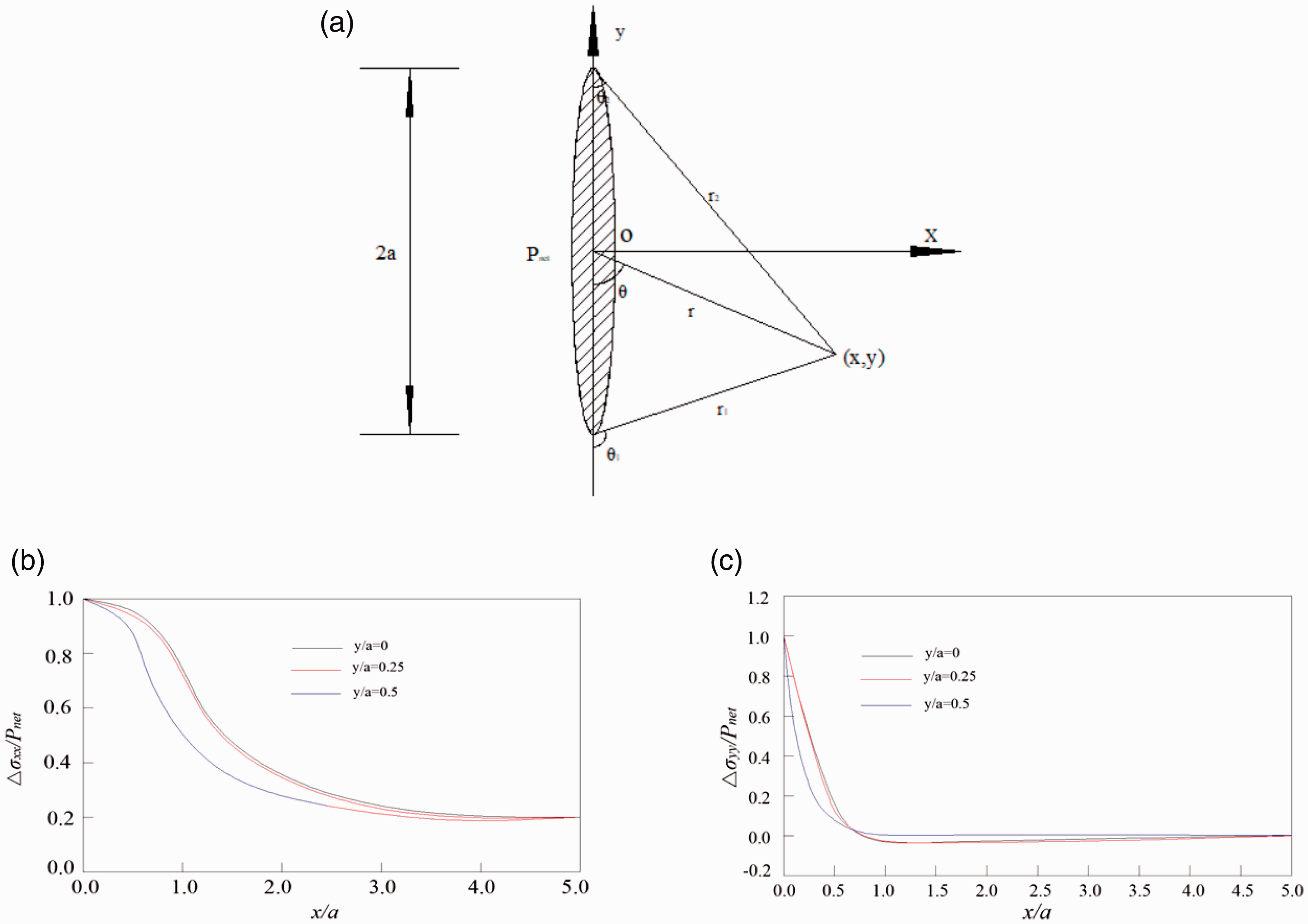
Assuming that the horizontal direction is the minimum principal stress σh direction and the vertical direction is the maximum principal stress σH direction, the induced stresses generated in the original minimum and maximum horizontal principal stress directions are △σh and △σH, respectively. The formula (2) is used to calculate the minimum and maximum stress σh′ and σH′ in the fracturing process.
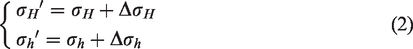
According to the definition of induced stress, the induced stress can be calculated by equation (3).
Therefore, the induced stress difference can be obtained by formula (4).

When the induced stress difference is larger than the original horizontal principal stress difference, principal stress reversal will occur. In the stress reversal zone, the hydraulic fracture extends along the new large main stress direction.
Mechanical equations of synchronous propagation of multiple fractures
A schematic diagram of the synchronous propagation of multiple fractures in a horizontal well is shown in Figure 2. With the boundary element displacement method used, a mechanical equation for the synchronous propagation of multiple fractures is established by Cheng (2016).
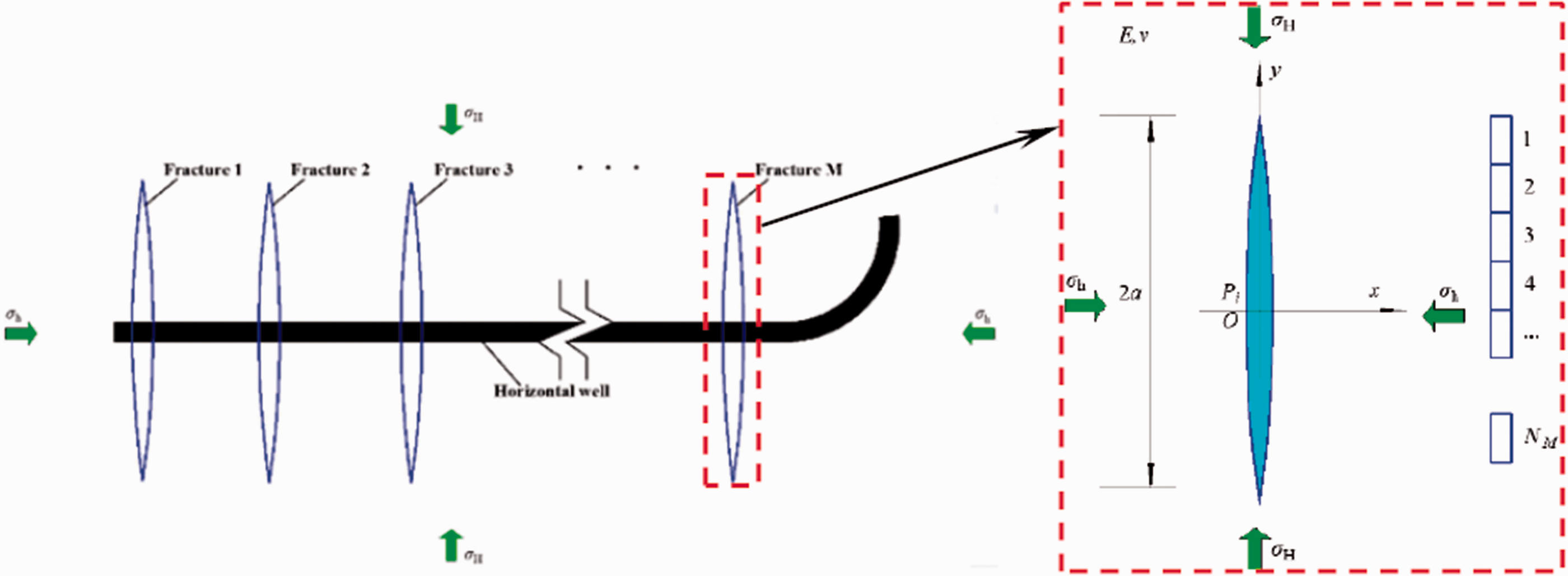
Schematic diagram of the simultaneous expansion of multiple fractures in a horizontal well (simultaneous expansion of M fractures) (Cheng, 2016).
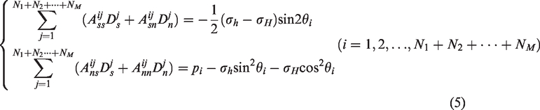
For brittle rocks, brittle fracture occurs once the elastic limit is reached. Therefore, fracture toughness can be used to describe the critical stress intensity factor at the fracture tip. If the intensity factor of the equivalent stress at the fracture tip exceeds the I-type fracture toughness, the hydraulic fracture will propagate. When M hydraulic fractures expand at the same time, the hydraulic fractures are divided into N1, N2, …, NM boundary units. These boundary elements can form an equation system, which is shown in equation (5) (Cheng, 2016).
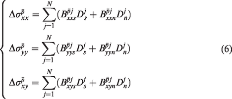
Substituting the in-situ stress, fluid pressure in the fracture and elastic parameters of the rock into equation (1), the discontinuous quantity of displacement can be solved. And then substituting the discontinuous quantity of displacement into equation (2), the induced stress field under the condition of synchronous propagation of multiple fractures can be obtained by equation (6) (Cheng, 2016).
According to the above-mentioned mechanical equation of multi-fracture synchronous propagation, the paths of three hydraulic fractures (with a fracture spacing of 30 meters) calculated by Cheng Wan et al. are shown in Figure 3. It is not difficult to see that the three hydraulic fractures are not of equal length. They are presented as repelling-shape and are symmetrically distributed on both sides of the wellbore. The propagation of the middle hydraulic fracture is disturbed by the stress of the hydraulic fractures on both sides, and it stops expanding after extending to a certain length. However, the middle fracture is always a straight fracture.
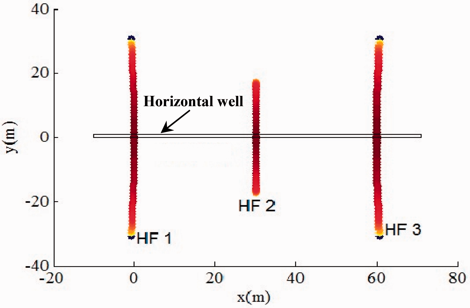
Propagation path of hydraulic fracture under the action of the induced stress field (Cheng, 2016).
Numerical simulation of induced stress field distribution among three parallel fractures
Compared with the induced stress field of a single fracture, the induced stress field between multiple parallel fractures under internal water pressure is more complex and difficult to quantitatively describe with a series of calculation formulas. However, the numerical simulation method is economical and simple and can be used to study the spatial distribution of induced stress fields between multiple parallel fractures.
Geometry model
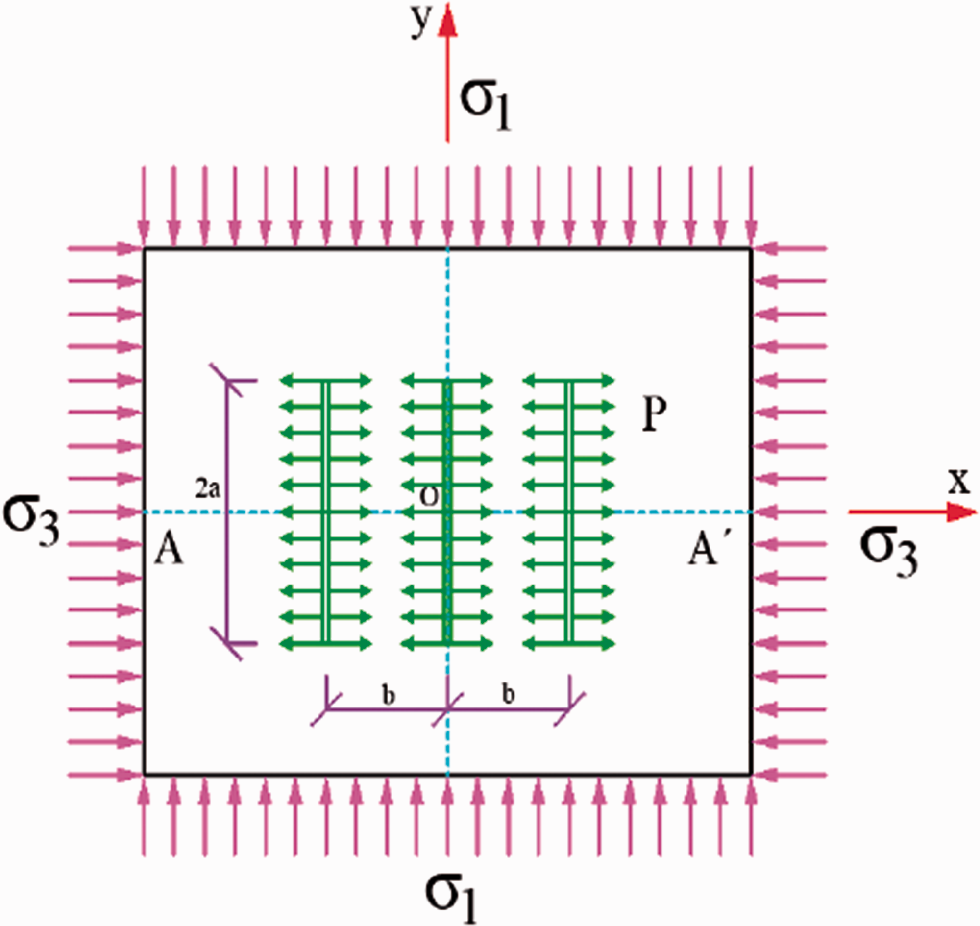
This numerical simulation used a two-dimensional plane strain seepage model with dimensions of 30 m × 30 m (Figure 4), which was divided into 300 plane strain seepage model with dimensions o were stress constraints and impermeable boundaries. The maximum principal stress σ H in the vertical direction was 45 MPa, and the horizontal direction was the minimum principal stress σ h direction, which was 30 MPa. Three parallel fractures of the same length are arranged in the plane model along the direction parallel to the maximum principal stress σH, and the horizontal distance between adjacent fractures was 5 m. A vertical fracture in the middle passed through the centre point of the model and was symmetrically arranged with a length of 5 m. A horizontal monitoring line AA′ over the centre was established, and the change rules of the maximum principal stress, the minimum principal stress, and principal stress difference on the section were monitored.
Geometry model.
Selection of numerical simulation parameters
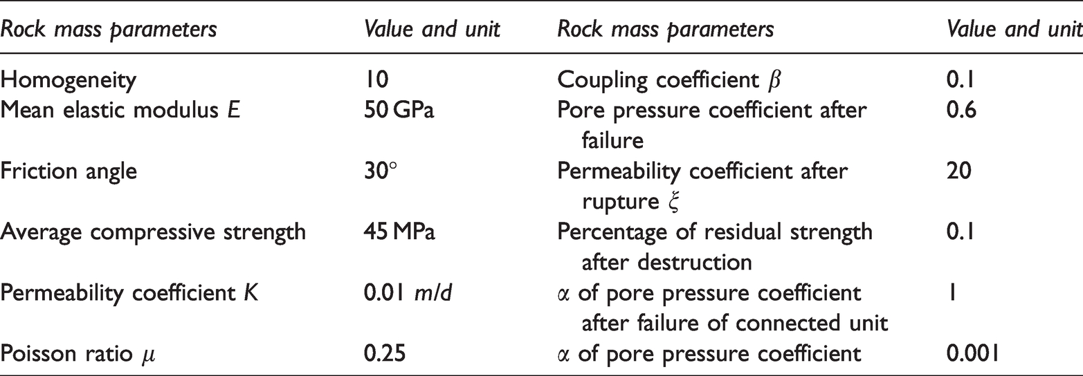
The relevant parameters used in this numerical simulation are shown in Table 1.
Numerical simulation parameters.
Analysis of the stress field induced by three parallel fractures
We established the maximum horizontal principal stress σH as 45 MPa and the minimum horizontal principal stress σ h as 30 MPa, keeping the water pressure in the prefabricated fracture at a constant value of 60 MPa.
Analysis of the induced stress field under different fracture lengths
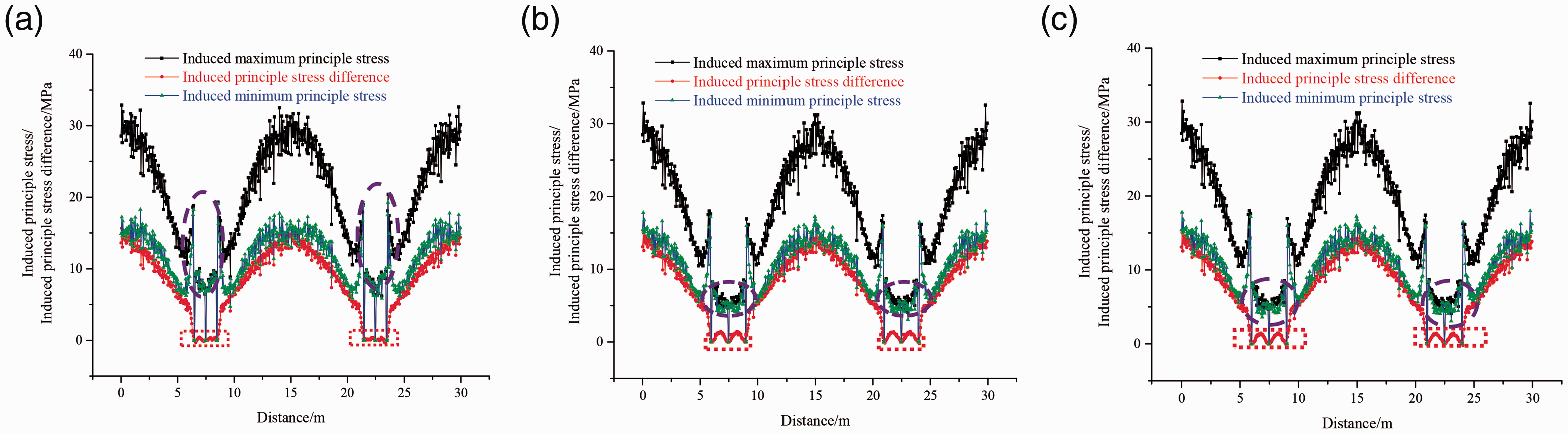
The spacing b between two adjacent fractures was 3 m, and the length 2a was 3 m, 5 m and 7 m. The induced stress in the x and y directions and its difference is shown in Figure 5. As shown in Figure 5: (1) variation trend of the induced stress and stress difference in the x and y directions of fractures at 3 m, 5 m and 7 m lengths were consistent overall. (2) In addition, induced stress in the x direction decreased gradually from the middle fracture to the two ends, kept a small range of fluctuations straight, and finally increased gradually. (3) Furthermore, the induced stress difference and induced stress in the y direction tended to be consistent. Different from the trend of induced stress in the x direction, there were three sudden drop points in each linear segment with corresponding small range fluctuations.
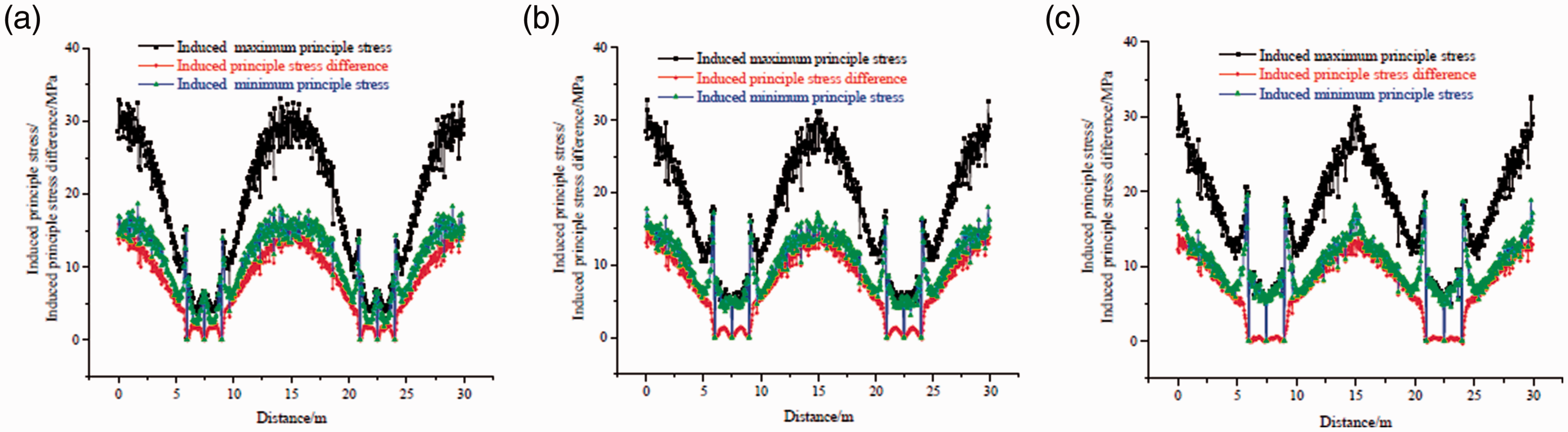
Induced stress (difference) with space distance under different fracture lengths. (a) l = 3 mm (b) l = 5 mm (c) l = 7 mm.
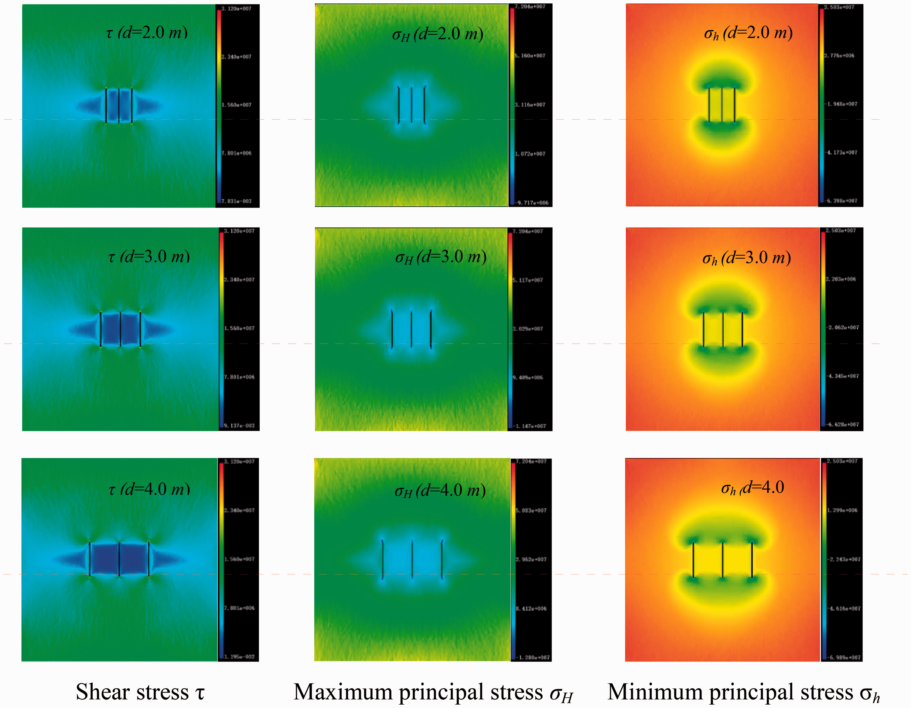
The water pressure induced stress field in the fracture was superimposed with the original ground stress field, and the composite stress field around the fracture can be obtained as shown in Figure 6.
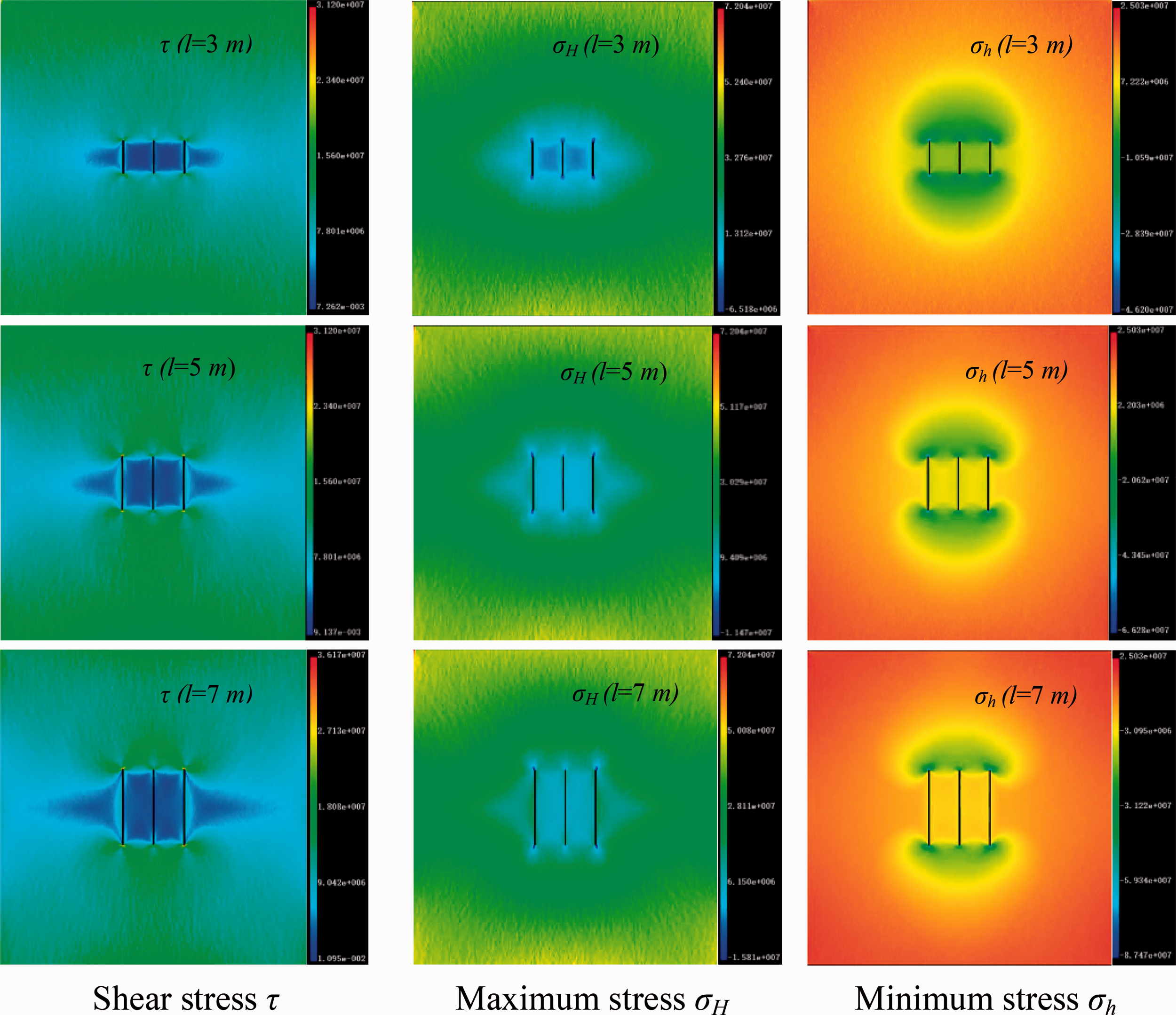
Composite stress field around fractures of different lengths.
Induced stress (difference) values for different fracture length.
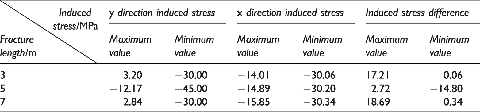
From Figure 6, we cannot intuitively compare the effect of fracture length on the induced stress and its difference. However, under the same fracture spacing and internal water pressure conditions, the change in principal stress in the y and x directions in the rock were related to the fracture length, which can be observed from Table 2. The maximum and minimum values of the induced stress and induced stress difference in the y direction decreased first and then increased with increasing seam length, and the maximum and minimum values of the induced stress in the x direction decreased with increasing fracture length.
Analysis of the induced stress field under different fracture spacings
All fractures were 5 m in length. The distances between two adjacent fractures were 2 m, 3 m, and 4 m along the AA′ monitoring line. Induced stress and its difference in x and y direction are shown in Figure 7. As shown in Figure 7: (1) the variation trend of induced stress and stress difference in the x and y directions under different fracture spacings were consistent as a whole. That is, the change curve morphology of the maximum principal stress, the minimum principal stress, and the induced principal stress difference with distance under different fracture spacings were consistent overall. (2) The difference in induced stress under different fracture spacings showed a gradual decrease from the middle fracture to the lateral fracture and maintained a small range of fluctuations. Finally, there was a gradual increase. The smaller the spacing was, the greater the maximum principal stress difference in a small range of fluctuations (as shown in the red rectangular dashed line frame). (3) Furthermore, as the fracture spacing increased, the overlapping region between the maximum principal stress and the minimum principal stress after induction showed separation (shown in the purple elliptical dashed line frame). The composite stress field around the fracture is shown in Figure 8.
Curve of induced stress (difference) with space distance under different fracture lengths. (a) d = 2.0 m (b) d = 3.0 m (c) d = 4.0 m.
Composite stress field around fractures of different lengths.
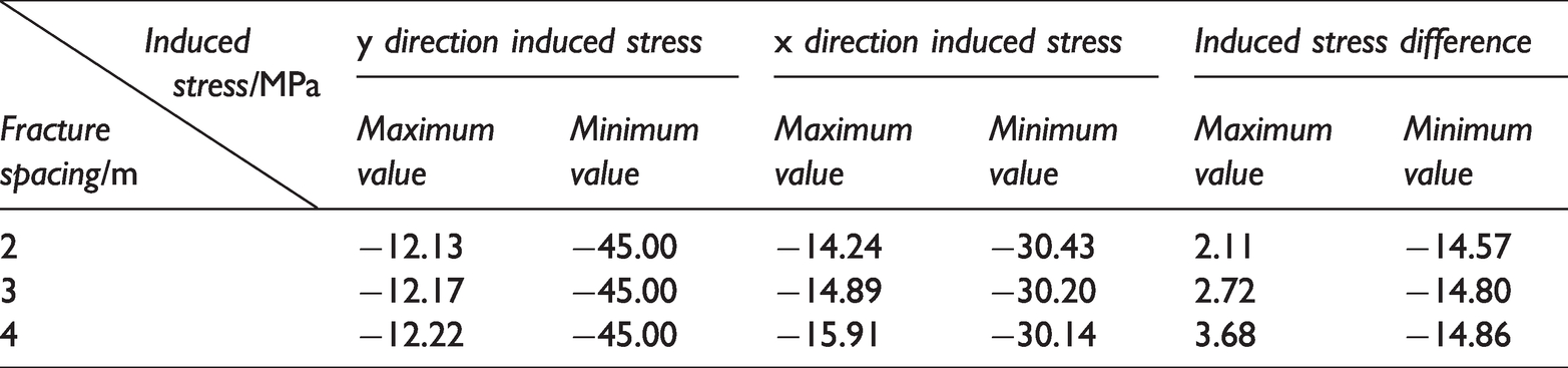
From Figure 8, we cannot intuitively compare the effect of fracture length on the induced stress and induced stress difference. However, from Table 3, we observed that under the same fracture length (5 m) and the internal water pressure (60 MPa) conditions, the variation in the principal stress in y and x of the rock was related to the fracture spacing. The maximum induced stress value in the x and y directions and the minimum induced stress difference value decreased with increasing fracture spacing. In addition, the minimum induced stress value and the maximum induced stress difference value in the x direction increased with increasing fracture spacing. The minimum induced stress value in the y direction hardly changed.
Induced stress (difference) values for different fracture spacing.
Analysis of the induced stress field under different principal stress ratios
We kept the distance between two adjacent fractures at 3 m, the length at 5 m, and the minimum principal stress at 30 MPa. By changing the maximum principal stress value, the principal stress ratio λ was 1, 1.5 and 2. Under different principal stress ratios, the induced stress and its difference in the x and y directions are shown in Figure 9. As shown in Figure 9: (1) under different principal stress conditions, the overall trends of the maximum and minimum principal stress and principal stress difference after induction were consistent. (2) Under different principal stress conditions, the maximum principal stress after induction decreased gradually from the middle fracture to the two sides, then maintained a straight line with small fluctuations, and finally gradually increased, showing a “W” shape. The greater the principal stress was, the greater the maximum principal stress corresponding to the point of the “W” shape. (3) Under different principal stress conditions, the induced stress difference was also similar to the “W” shape overall. However, there was some fluctuation at the “W” trough. This fluctuation region corresponded to the fluctuation of the induced stress difference near the outer two fractures. Notably, when λ = 1, the induced principal stress difference was negative, indicating a reversal of the maximum and minimum principal stress phenomena. This was due to the stress interference when the three fractures extended simultaneously. This principal stress reversal in turn affected expansion of the three fractures. (4) Furthermore, the minimum and maximum principal stresses after induction overlapped within a certain area near the lateral fracture (Figure 9(a)). However, as the principal stress ratio increased, this overlap gradually weakened (Figure 9(b) and (c)). The composite stress field around the fracture is shown in Figure 10.
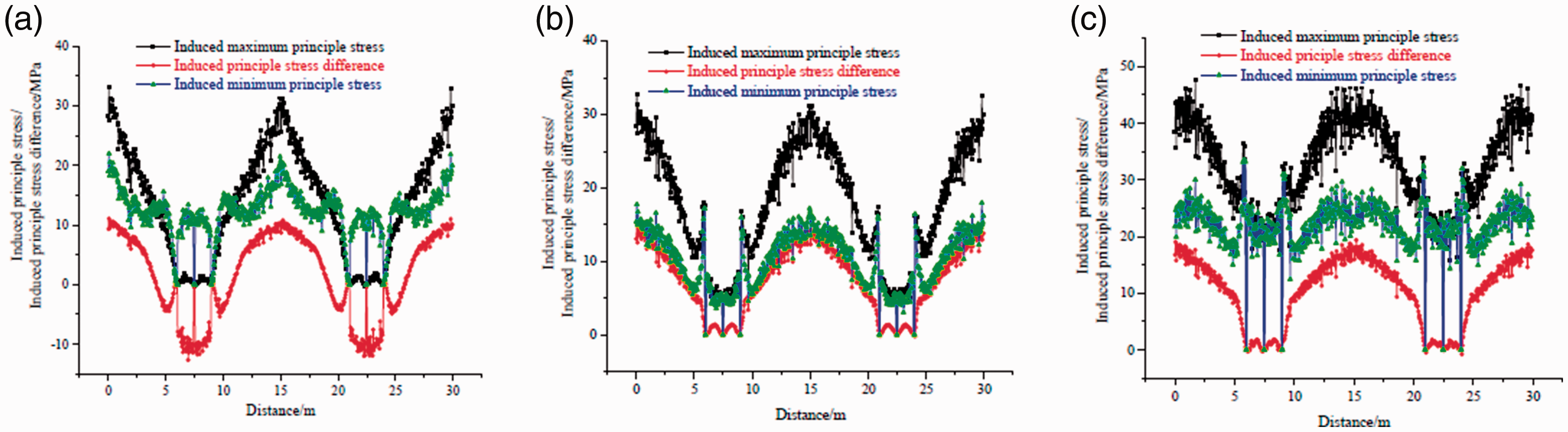
Curve of induced stress (difference) with spacing distance under different fracture lengths. (a) λ = 1.0 (b) λ = 1.5 (c) λ = 2.0.
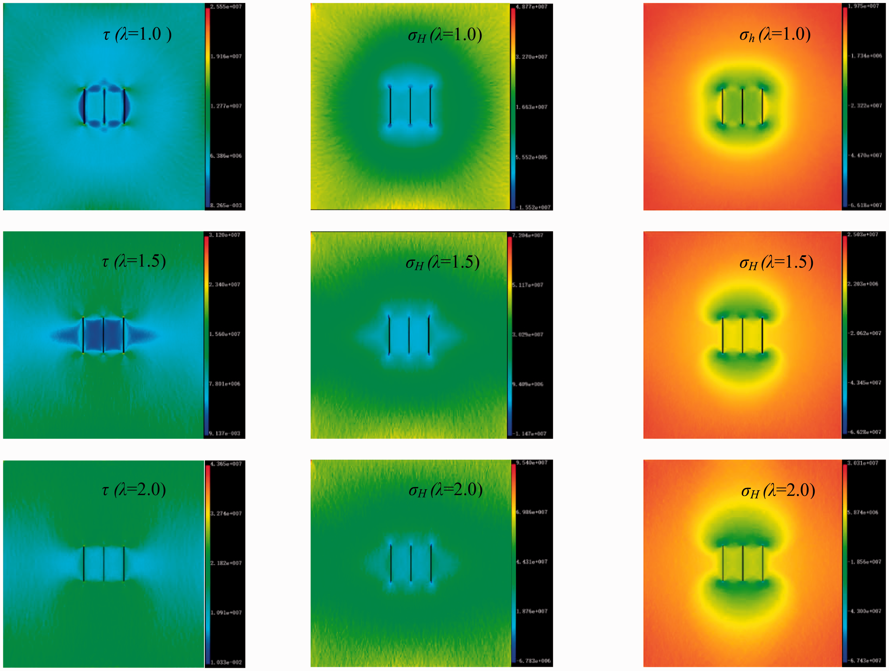
Composite stress field around fractures of different lengths.
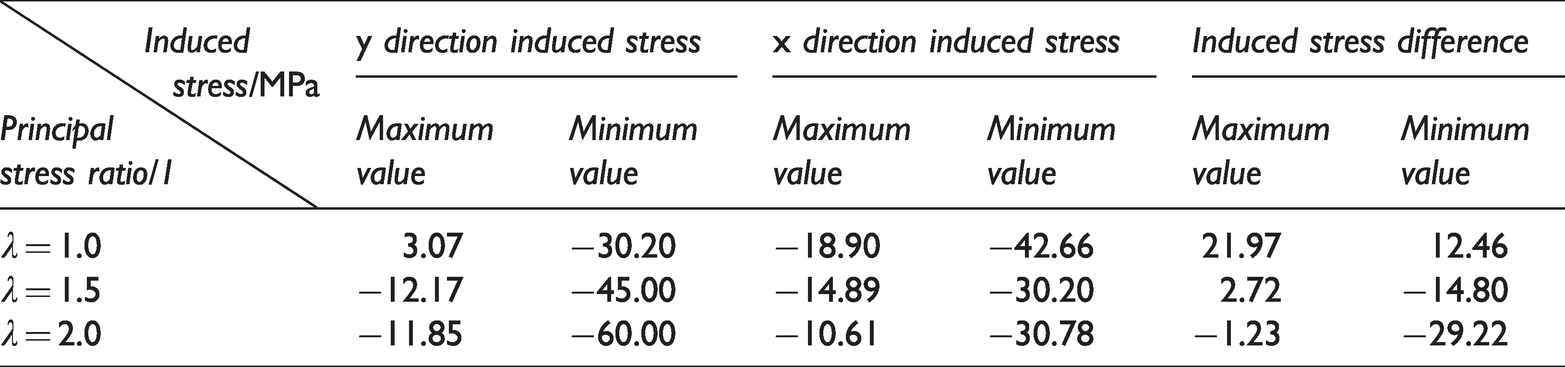
From Figure 10, we cannot intuitively compare the effect of fracture length on the induced stress and its difference. However, from Table 4, we found that under the same fracture spacing and internal water pressure conditions, the variation in principal stress in the y direction and x direction in the rock was related to the maximum and minimum principal stress ratios. The maximum and minimum induced stress and the induced stress difference values in the y direction decreased with increasing principal stress ratio, and the maximum and minimum induced stress values in the x direction increased gradually with increasing principal stress ratio.
Induced stress (difference) values for different principal stress ratio.
Fracture propagation in the process of the parallel multi-fracture synchronous hydraulic fracturing
When multiple fractures were arranged in parallel, they interfered with each other, affecting the fracture extension length and direction. This made it more difficult for the effective fracture to form in the middle position, thereby stopping the fracture. This phenomenon was particularly evident when multiple parallel fractures occurred at the same time. The fracture extension pressure was jointly affected by the far-field in situ stress state, reservoir lithology, fracture geometry size, and flow pressure distribution within the fracture. The in-situ stress state, especially the minimum principal stress perpendicular to the fracture surface, directly affected the fracture extension difficulty.
Effect of fracture spacing on the process of the hydraulic fracturing
While keeping the other parameters unchanged, we changed the adjacent fracture horizontal spacing to 2 m, 2.5 m, 3 m, 3.5 m, and 4 m. The corresponding maximum principal stress distribution cloud diagram is shown in Figure 11. The results show that: (1) during the 10show thatwhen the distance between adjacent fractures was 2 m, 2.5 m and 3 m, the middle fracture did not propagate in the vertical direction. With increasing fracture spacing, the degree of deflection of the fractures on both sides of the calculation step increased gradually. In addition, it is important to stress that the hydraulic fracture occurred at step 90, and the middle fracture had a fracture spacing of 2 m. This may have been attributed to water pressure in the fracture changing the direction of the maximum principal stress in some areas around the intermediate fracture so that the hydraulic fracture in the induced area extended along the horizontal direction and no longer along the vertical direction. (2) When the fracture spacing was 3.5 m, the expansion speed of the intermediate hydraulic fracture lagged behind the hydraulic fracture expansion on both sides at the initial stage, and then its expansion speed accelerated. Li Wang and others defined it as the “expansion inhibition period” and “secondary expansion period” for the middle fracture (Li et al., 2016, 2018a). Combined with the abovementioned induced stress changes during the simultaneous water injection in the three fractures, this phenomenon is explained as follows. During simultaneous extension of multiple parallel fractures, the induced stress difference in the middle area and the principal stress increment in the vertical fracture plane were large, and the fracture extension velocity slowed down or stopped relatively to the fractures on its both sides. With hydraulic fracture expansion, the fluid pressure in the fracture increased gradually, while the main stress increment and induced stress difference in the vertical fracture direction decreased significantly. Under certain stress conditions, the middle fracture may break through and continue to extend. However, with small fracture spacing, there was no “secondary expansion period”. In addition, the deflection direction of the intermediate fracture extension was consistent with the fracture expansion direction with a large deflection angle on both sides. The root cause was that the maximum principal stress in the inter-fracture region was redistributed because of the induced stress. The intermediate fracture was inclined to expand along the maximum principal stress after redistribution. (3) In addition, compared with the hydraulic fracture in step 90, we found that the hydraulic fracture extension direction deflection on one side was affected by the hydraulic fracture on the other side with no obvious intermediate fracture interference. (4) Furthermore, when the hydraulic fracture in the middle was extended, the induced stress between the three fractures were superimposed and affected each other, which eventually led to greater hydraulic fracture bending on both sides.
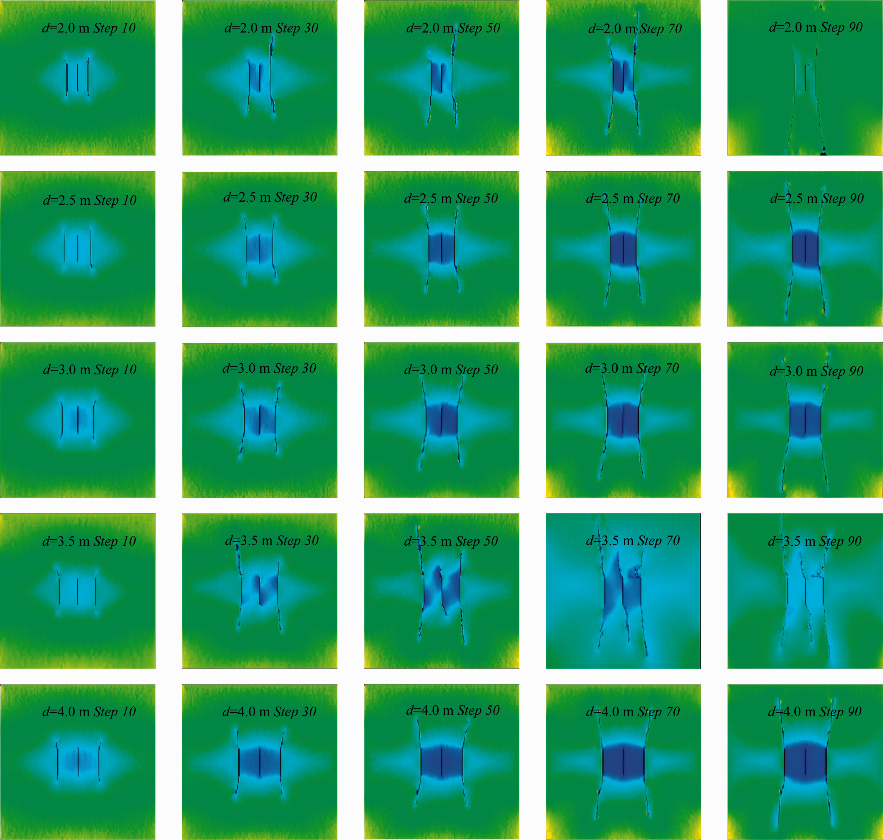
Effect of induced stress from different fracture spacing on hydraulic fracture expansion.
In summary, when the fracture spacing was small (2he m), the maximum horizontal principal stress at the centre of the model increased, and the middle fracture did not stop. With increasing fracture spacing, the intermediate fracture arrest length increased gradually. When the fracture spacing increased to a certain extent, the middle fracture, like the fractures on both sides, also began to extend and no longer appeared to arrest the fracture. However, in early hydraulic fracturing, intermediate fracture expansion was slow, which was caused by the hydraulic fracture extrusion on both sides. According to the experimental results, it was not difficult to conclude that during multi-stage cluster hydraulic fracturing, there was lower reservoir transformation efficiency and poor permeability from the larger cluster spacing. In addition, the induced stress caused by the smaller cluster spacing inhibited the intermediate fracture expansion. Therefore, there was a critical fracture spacing during multi-cluster hydraulic fracturing, which made the reservoir permeability the best.
Effect of the main stress ratio on the process of the hydraulic fracturing
We maintained a fracture spacing of 3 m and a minimum horizontal principal stress σh of 30 MPa. We changed the maximum horizontal principal stress σH value to study the hydraulic fracture propagation principal stress ratio λ (λ = σ1/σ3) at 1, 1.25, 1.5, 1.75, and 2. The results (Figure 12) show that under different principal stress ratios, there were obvious differences in hydraulic fracture shapes. When the principal stress ratio was λ 1 and 1.25, there was bifurcation propagation along the direction of minimum horizontal stress in the middle hydraulic fractures because the induced stress difference was easily offset by the smaller original level minimum principal stress difference. The principal stress direction in the intermediate fracture local area was reversed, resulting in fracture initiation and propagation along the new maximum horizontal principal stress direction, producing a split fracture. With hydraulic fracture expansion for λ at 1 and 1.25, the expansion speed of the former was faster than that of the latter. For λ at 1, 1.25 and 1.5, we observed the middle hydraulic fractures stopping. For λ at 1.75, the hydraulic fracture expansion stopped after a long distance, whereas for λ at 2, the early intermediate fracture initiation and propagation lagged behind the expansion of the two sides of the fracture with the hydraulic fracture expansion speed in the later stage exceeding that on the sides. As λ increased, the degree of fracture outward bending on both sides gradually decreased, the initiation difficulty of the middle fracture gradually decreased, and the expansion speed of the fractures on both sides was gradually reduced. The reason for this was that the initial minimum horizontal principal stress and fluid pressure in the fracture were synchronized, and there were no obvious differences between the net pressure in the fracture and the induced stress distribution around the fracture. A larger σH principal stress difference occurred around each fracture, and fracture initiation and expansion became increasingly difficult.
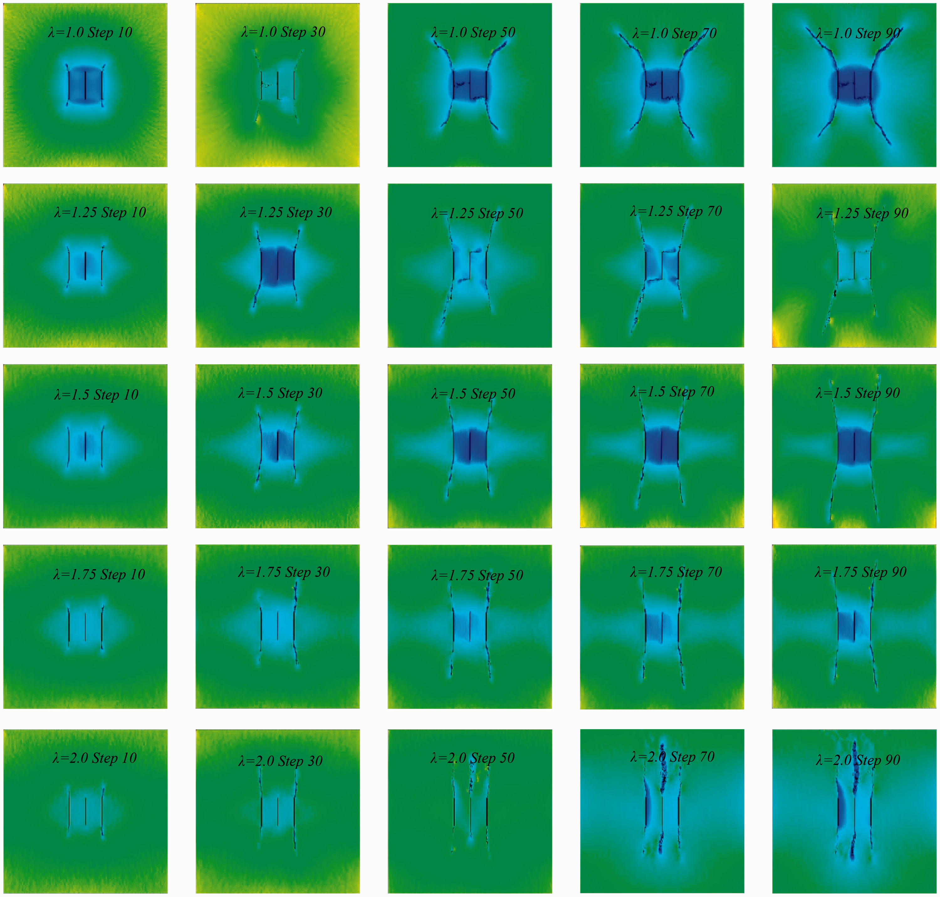
Effect of induced stress from different principal stress ratios on the propagation of hydraulic fractures.
Conclusions
Induced stress increment occurred in the area around the hydraulic fracture. Induced stress played a dual role in the fracturing process. It created favourable in situ stress conditions for steering hydraulic fractures and forming complex fracture network systems. It also inhibited fracture expansion in local areas and even arrested hydraulic fractures and hindered effective fracture formation. The curves of the maximum principal stress, minimum principal stress, and induced principal stress difference with distance under different fracture lengths, different fracture spacings and different principal stress ratios were consistent overall. With small fracture spacing and a small main stress ratio, intermediate hydraulic fractures were difficult to initiate and expand, and the expansion speed of the lateral hydraulic fracture was fast. Moreover, with small fracture spacing and a small main stress ratio, hydraulic fractures were more prone to steering, and even new fractures were produced in the direction of minimum main stress, which was beneficial to the fracture network communication in the reservoir. When the local stress and fracture spacing were appropriate, the intermediate fracture expanded normally and could effectively increase the reservoir permeability.
Footnotes
Declaration of conflicting interests
The author(s) declared no potential conflicts of interest with respect to the research, authorship, and/or publication of this article.
Funding
The author(s) disclosed receipt of the following financial support for the research, authorship, and/or publication of this article: This work was supported by Transformation of Scientific and Technological Achievements Programs of Higher Education Institutions in Shanxi (TSTAP) (No. 2020CG050), Special Project of 2019 Plan for the Introduction of High-level Scientific and Technological Talents in Development Zone of Lvliang City (Development of automatic disassembly platform for hydraulic support pin shaft) (No. 2019102), Science and Technology Project of Lvliang City in 2019 (Pressure relief and permeability improvement technology by integrated hydraulic flushing and cutting for low permeability coal seam containing methane) (No. GXZDYF2019080), School-Level Teaching Reform and Innovation Projects of Luliang University in 2020 (No. JXGG202039).