
Abstract
The multistage stimulation technique and horizontal wells are increasingly being utilized to improve oil and gas recovery. However, the sticking that occurs due to large drag during the completion string with packers tripping into the horizontal section, resulting in an abandoned well and huge economic losses. Based on a classical drag model, this paper illustrates how local drags affect the overall stress of the completion string by a case study. Mechanical models are also presented for analyzing the local drag of packers in horizontal sections considering the effects of microsteps or slots, borehole curvatures, and caliper variation respectively. The results confirmed that the local contact force is affected by centralizers, and local drags can be magnified during their upward transmission process. It is revealed that the slopes of microsteps or slots affect more on local drag of packers than the effects of microsteps’s height and slots’ depth; Moreover, the local drag of the packer was found increases with the increase of the borehole curvature, but less affected by the caliper variation; As to the effect of cuttings on the local drag of packers, it is affected by cuttings size and cuttings amount and cannot be quantitatively analyzed. This research could be utilized as a theoretical reference for estimating the sticking risks of the completion string and conditioning the horizontal open hole.
Introduction
The horizontal well technology has been widely applied with the increase of development of oil and gas resources (Mason and Judzis, 1998; Viktorin et al., 2006), and the extension record of horizontal wells has been continuously updated with the advancement of horizontal well technology (Gao et al., 2009; Michael, 2012; Sonowal et al., 2009). Moreover, with the development of the directional drilling technology and measurement tools, many kinds of complex-structure wells have been drilled on the basis of horizontal wells (Gao, 2011). After the first U-shaped well in the world was drilled successfully under complex ground conditions (Lee and Brandao, 2005), Eni oil company has initiated an R&D project to realize a continuous circulation of a superheated fluid across a lengthy horizontal section of two interconnected horizontal wells (Poloni et al., 2010), and the most critical point, the intersecting process of U-shaped horizontal wells has been further studied (Xi et al., 2015). The main bore as well as multiple lateral branches can be drilled in the reservoir by multilateral wells technology, which is mainly used in Coal bed Methane (CBM) (Gao and Xian, 2007), and a lot of related studies have been done (Retnanto, 1996). By magnetic guidance technology for directional drilling in steam-assisted gravity drainage (SAGD) wells (Gao et al., 2013), two parallel horizontal wells can be created 5 m away from each other in the vertical direction to enhance the oil recovery of heavy oil reservoirs.
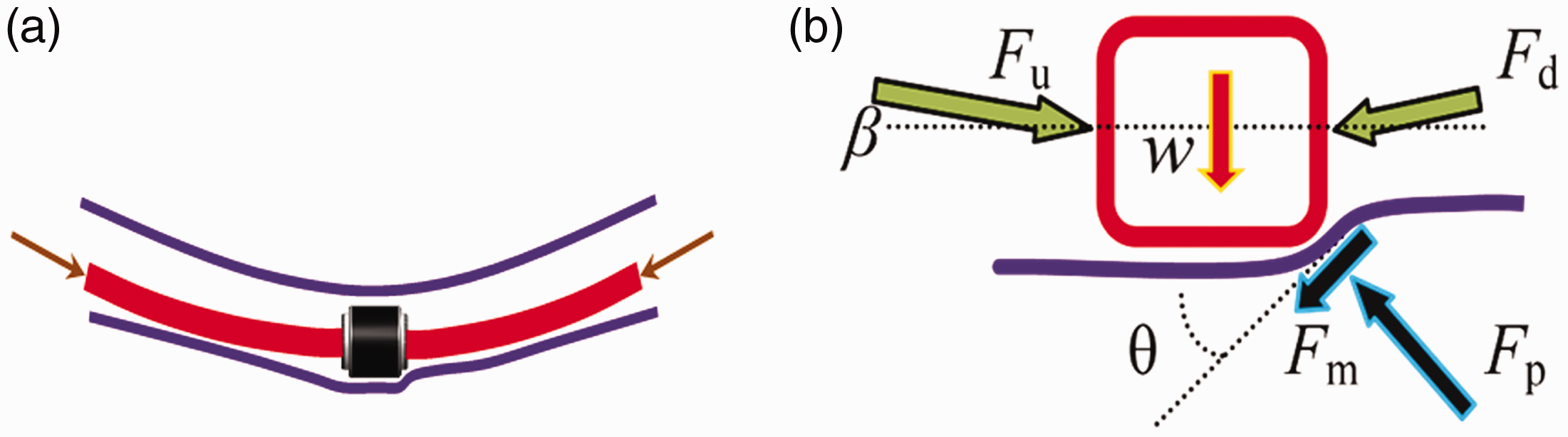
With the advancement of the completion technology, there are many completion types for horizontal wells, such as open hole, cased and cemented, screen pipe completion, and sliding sleeves with packers. A large number of production practices show that the fracturing technology is the most effective one to bring the best stimulation results and huge benefits to the development of oil and gas fields (McDaniel et al., 2002). This is mostly because hydraulic fracturing generally leads to highly complex hydraulic networks in reservoirs, which can enhance the well performance significantly (Yuan et al., 2018). The multistage stimulation technique is commonly used in low permeability reservoirs (Wang et al., 2019), such as tight gas reservoirs (Wang et al., 2020) and dolomite reservoirs (Willett et al., 2002). Figure 1 shows a typical schematic of the completion string with packers in the horizontal well. When the completion string with packers trips into the long open hole section of a horizontal well, the drag of the completion string is actually changing constantly.
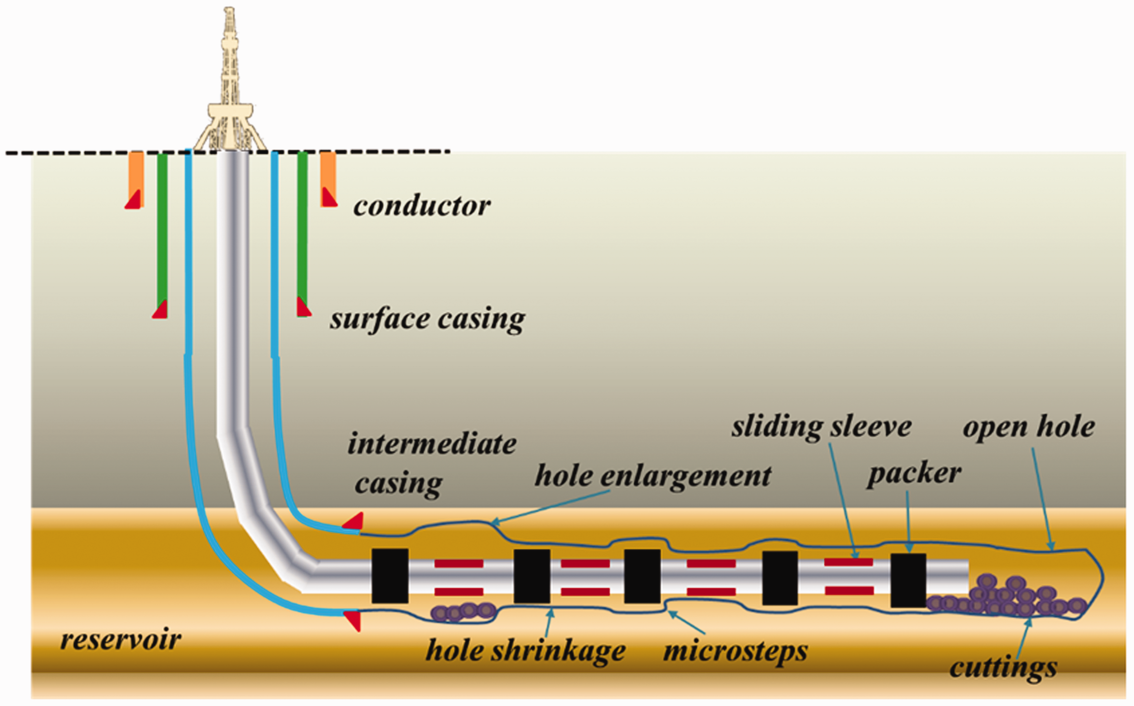
Schematic of the completion string with packers in the horizontal well.
However, the sticking problem of the completion string with packers is frequently encountered in the horizontal section (Zhang, 2011). At this time, three types of measures are generally taken to free the completion string, and the basic steps are as follows. (1) Gradually reduce the hook load; (2) Try to pick-up the completion string; (3) Pump on to circulate the drilling fluid while reciprocating the string. If unsuccessful, it should complete the well there or trip out the entire string and wiper trip to condition the hole, and then trip in again. The stuck-freeing effect by reciprocating the completion string within its safe strength range is generally not obvious and rarely successful. Although pumping on to circulate the drilling fluid while reciprocating the completion string may improve the stuck effect, it does not result in total release in most cases. The completion string is mainly composed of a tubing or casing, which cannot be rotated, as a drill pipe. Thus, the entire completion string is scrapped due to thread damage after being pulled out of the hole. In this circumstance, and the rest of horizontal interval cannot be stimulated, resulting in the abandonment of the whole well and huge economic losses (Franco et al., 2008).
The sticking of the completion string is closely related to its friction, and two classic torque and drag models of pipe string mainly exist, namely, the soft rope model (Johancsik et al., 1984) and rigid rod model (Ho, 1988). In these models, the drill string axis is assumed to coincide with the borehole axis, and the radial clearance between the string and the borehole is ignored. The bending stiffness of the string is also ignored in the soft rope model, making its calculation simpler and more convenient than that in the rigid rod model. Lubinski (1950), Dawson and Paslay (1984), Paslay and Bogy (1964) conducted intensive research on the critical load of sinusoidal buckling and obtained a consistent calculation formula. Many scholars, such as Dawson and Paslay (1984), Paslay and Bogy (1964), Mitchell (1988), Chen et al. (1990) have deduced helical buckling equation under their respective assumptions. Until now, the above have been widely used to analyze stresses of the completion string and have been proved to be effective in most cases. However, the stuck point in the horizontal section is typical uncertain and not necessarily related to the length of the horizontal section. The stuck point is sometimes very near the total depth of the hole and not far from the landing point at other times. According to the sticking phenomenon and typical characteristics during the operation of the completion string, it can be found that the sticking is closely related to the completion string structure and the downhole condition, and the local drag in the irregular actual open hole is the main reason for the sticking of the completion string. Generally, the factors of the local drag mainly include the following aspects: (1) Affected by the geology engineering or directional tools, the actual trajectory of the horizontal well is not drilled like an ideal straight line as designed, but with dogleg severity in some intervals (Gao et al., 2006; Zhang and Di, 2000).This kind of situation is common when using a mud motor to control the well trajectory of the horizontal section. These horizontal intervals with dogleg severity introduce additional drag to the completion string. (2) During pull out from a hole or a short wiper trip operation, micro slots can be formed by the grinding force of the drill string in these intervals with high dogleg severity (Huang and Gao, 2020). These slots will have little influence on the drag of the drill string with small joints, but will bring great drag to tools with a large outside diameter, such as centralizers or packers. (3) The borehole diameter is generally irregular due to the borehole enlargement caused by cave-in or collapse in some intervals and borehole shrinkage in others (Huang, 2016). The transition intervals will have microsteps between these irregular well sections or the joints between them and the sections with normal borehole diameter, and this phenomenon is obvious in heterogeneous reservoirs. If multiple packers or centralizers pass through these microsteps, then the sticking problem will definitely occur. (4) Some cuttings produced during drilling are not fully carried to the surface due to the unreasonable properties of the drilling fluid or the circulation parameters before running in the completion string and remain on the lower side of the wellbore due to gravity (Li et al., 2017). Either the downhole cuttings are left in the inclined section or the horizontal section, additional friction is introduced to the completion string. Especially when the completion string has packers with a larger outside diameter, the rubber sleeve of the packer will “clean and pile” the remaining cuttings in the wellbore. When the thickness of the cuttings bed is large after a certain length of accumulation, the completion string can no longer be run in and sticking occurs.
Actually, local mechanical drags caused by the above reasons will accumulate and produce an amplification effect as the length of the horizontal section increases (Wu, 1995). However, the local drag effect of the packers is ignored in the overall stress model of the completion string (Huang et al., 2018). Consequently, the completion string sticking’s problem is difficult to simulate accurately. The local drag analysis of the completion string was qualitatively carried out, but not quantitatively verified. Therefore, the prevention and treatment measures rely mainly on experience and lack systematic theoretical guidance.
In this paper, the cumulative amplification effect of the local drag is verified and the influence factors of the local drag of the completion string are analyzed based on the classical model of drag and torque. Mechanical models are built for analyzing the local drag of packers in horizontal sections considering the effects of microsteps or slots, borehole curvatures, and caliper variation respectively. Moreover, how to manage these influence factors to prevent the sticking of the completion string are also presented.
Materials and methods
Calculation model
Until now, the theoretical research on tubular mechanics is very mature; thus, the classical calculation equations of the torque and drag of the completion string (Ye et al., 2011) have been widely applied in drilling and casing running and proved to be effective.


Amplification effect of local drags
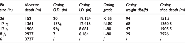
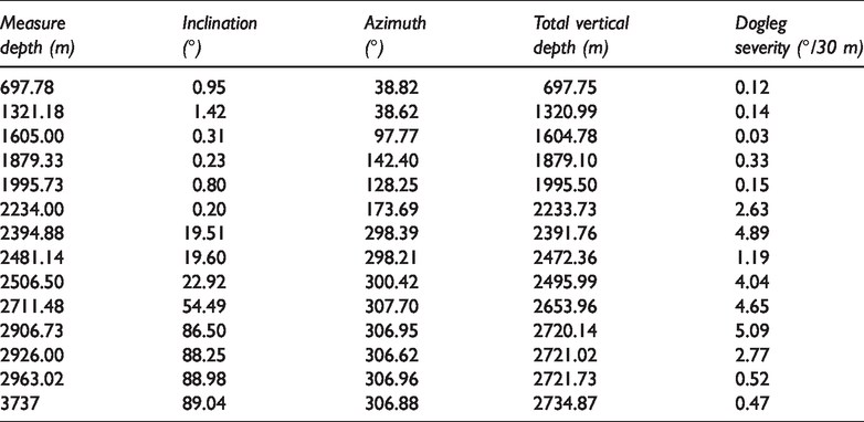
The actual data of an S well drilled in Iraq is taken as an example to carry out the following relevant calculation and analysis. The total depth of the well is 3737 m, the kick-off point is 2234 m, and the open hole section is from 2926 m to 3737 m in a carbonate reservoir named Sadi. KCl Polymer drilling fluid with a density of 1.23 g/cm3 was used. The weight of the traveling block is 20.5 Tons. The casing program parameters and the main well trajectory of this well are shown in Tables 1 and 2, respectively. The well profile of this horizontal well is shown in Figure 2. The completion liner in the horizontal section is mainly composed of a tubing (outside diameter 114.3 mm, inside diameter 101.6 mm), packers (outer diameter 143 mm, length 3 m, weight 50 kg/m), and pitching sliding sleeves with different spacing in between, and the spacing between two offset packers is 105 m. The liner running string from top to bottom includes a 4″ drill pipe with 74 stands, a 4″ heavy weight drill pipe with 8 stands, the 4″ DP with7 stands, a liner hanger (outer diameter 143 mm, length 4 m, weight 100 kg/m), and the 4.5″ tubing with 40 joints. The linear weights of the 4″ drill pipe, the 4″ heavy weight drill pipe, and the 4.5″ tubing are 24.43, 44.2, and 18.75 kg/m, respectively. The tripping speed of the completion string is 0.3 m/s, and the bit has no torque and weight on bit (WOB). The friction coefficients in the casing and the open hole are 0.25 and 0.3 respectively. Unless otherwise stated in the calculations below, the above parameters are used.
The casing program of S well.
The well trajectory of S well.
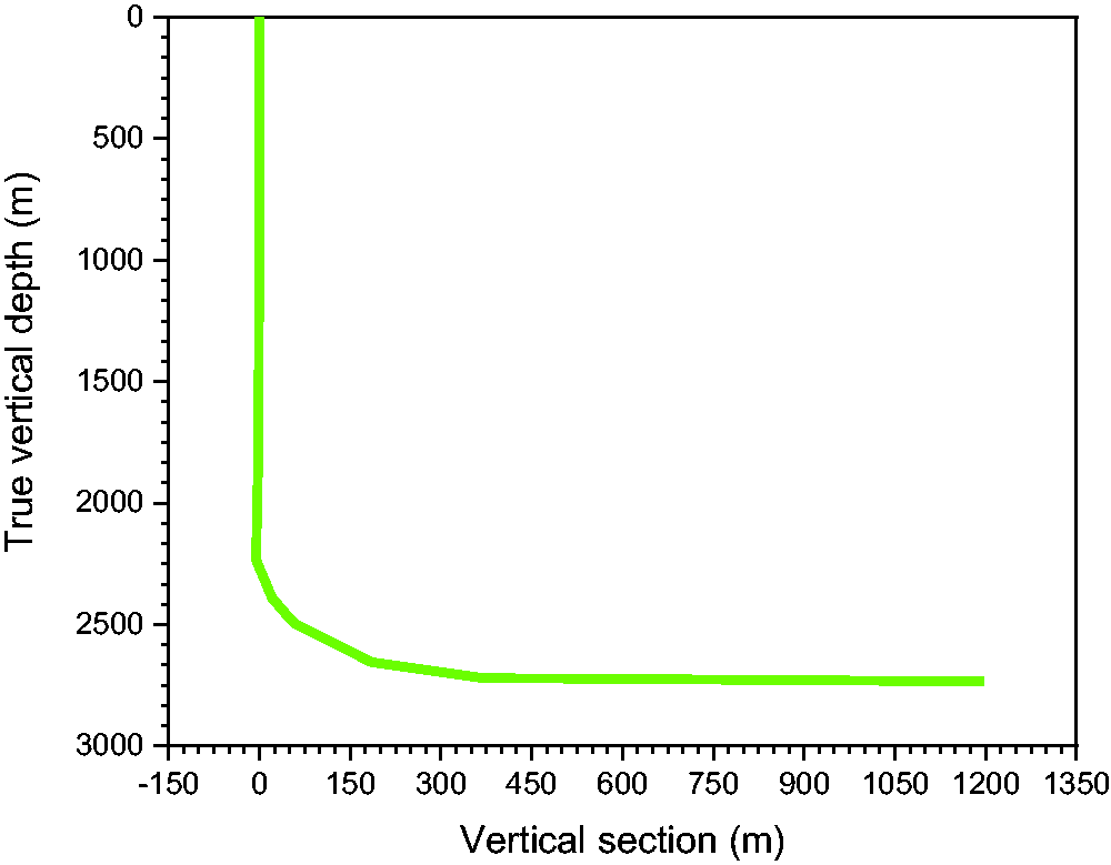
Well profile of the horizontal well.
Contact behaviors of packers and the horizontal wellbore
The completion string with packers will be under compression during tripping into the horizontal section. Thus, the contact force between the packers and the wellbore will be affected by the structure of the completion string. If the drill bit size for the horizontal section is 152.4 mm, then the completion string is mainly composed of a tubing (outside diameter 114.3 mm, inside diameter 101.6 mm, linear weight 0.18 kN/m). Thus, the annulus clearance with the wellbore is 19.05 mm, and the flexural rigidity EI is 6.607 × 10⁵ N·m2; the annulus clearance of the wellbore and the packers (outer diameter 143 mm, length 3 m, weight 50 kg/m) in the completion string is 4.7 mm. Centralizers are often installed in the completion string to improve the stand-off effect of the completion string, while in most cases, no centralizers are added in the completion string to reduce the drag during tripping if the fracturing result is unaffected. Under the assumption that the horizontal section has no curvature and the borehole diameter is regular, two kinds of conditions of the completion string, namely, with centralizers and without centralizers, are discussed in this paper respectively.
Effect of microsteps or slots on local drags
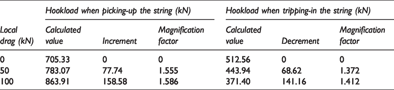
A completion string with packers moves forward in the horizontal section mainly by axial force. If the lower side of the horizontal section has a microstep or slot, and the wellbore has a curvature, then the local mechanical model of the packer in the microstep or slot is as shown in Figure 3 according to the actual downhole situation of the completion string with the packer, where Fu and Fd are the axial forces at both sides of the packer, kN; w is the weight of the packer, kN; Fp is the normal contact force on the packer in the microstep, kN; Fm is the tangential friction between the microstep and the packer, kN; θ is the slope of the microstep with the horizontal section, degrees; and μ is the friction coefficient between the microstep and the packer, β is taken as the angle between the axial force and the packer axis, which is generally very small.
Local mechanical model of the packer in the horizontal section with the microstep and curvature: (a) Schematic of the packer, microstep and curvature; and (b) local mechanical model.
According to the mechanical model in Figure 3, the following mechanical balance equation can be obtained:


Effect of dogleg severities on local drags
In general, the wiper trip operation is carried out to condition the microsteps in the hole before tripping-in the completion string, so other factors that have less influence could be ignored. According to the mechanical model in Figure 3, the mechanical balance equation can be obtained:


Results and discussion
Amplified effect of local drags
Effect of local drag values
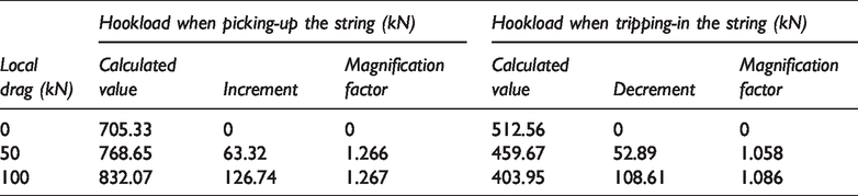
If the completion string has local axial drag forces of approximately 50 kN and 100 kN at the bottom of the S well, then the corresponding hook load results are as shown in Table 3. The increment and decrement of the hook load are relative to the hook load in the absence of local drag. The “magnification factor” is the ratio of the increment or decrement of the hook load to the local drag.
Effect of local drag at the bottom of the S well on hook load.
The above calculations indicate that the local drag variation of the completion string at the bottom of the horizontal well is not reflected in the total drag variation on the hook load, confirming that the local drag would be amplified during the upward transmission process. Under the same local drag condition, the local drag amplification effect is more obvious when picking up the completion string than when tripping in it. The amplification effect will increase with the local drag, but not linearly.
Effect of local drag positions
When the completion string is at the bottom of the S well, if 50 and 100 kN local axial drags exist separately at the middle of the deviated section at 2580 m (1156 m from the bottom hole) , then the hook load variation results as shown in Table 4. If the local drag position is at the upper vertical well section at approximately 2230 m (1506 m from the bottom hole), then the hook load variation results are shown in Table 5.
Effect of local drag at the middle of deviated section on the hook load.
Effect of local drag in vertical section on the hook load.
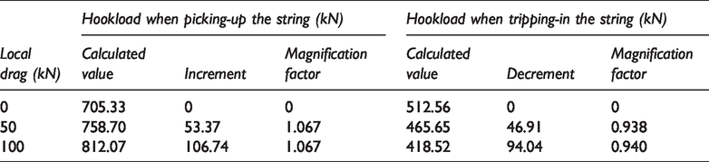
The two tables above show that the amplification factor of the local drag decreases as the stuck point moves up. If the local drag is above the kick-off point, then the magnification factor will be slightly less than 1 when tripping in the completion string, and slightly greater than 1 when picking it up. This phenomenon can be mainly attributed to the small dog leg severity in the vertical section of the above calculation case. If the vertical section is ideally straight, then the amplification factor should be 1.
Contact behaviors of packers and the horizontal wellbore
Completion string without centralizers
If the completion string has no centralizers, then the contact force between the packer and the wellbore will change with the axial force, and the distance from the packer to the nearest contact point of the completion string with the wellbore also changes with the axial force. The results are shown in Figure 4. The contact force between the packer and the wellbore is mainly caused by the packer’s gravity, and the relationship of the contact and axial force can be obtained from the curve-fitting in Figure 4.
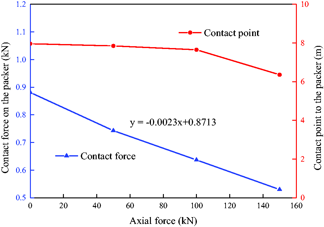
Effect of axial force on contact forces and contact positions.
The above calculation results show that the critical buckling value of completion string is 149.92 kN due to the axial force in the horizontal section. When the axial force exceeds this value, the contact force between the packer and the wellbore is calculated according to the buckling state of the completion string. When the completion string in the horizontal section has no axial force, the distance from the packer to the closest contact point of the completion string with the wellbore is 7.962 m, and the contact force between the packer and the wellbore is 0.8713 kN due to the packer’s self-gravity. Considering the actual size of the wellbore and the completion string and combined with the range of axial force on the string, the packer will touch the lower side of the wellbore due to the packer’s gravity. the contact point of the completion string around the packer with the wellbore approaches the packer as the axial force on both sides of the packer increases, so the contact force between the packer and the wellbore decreases. If no buckling occurs in the completion string, then the contact force between the packer and the wellbore is mainly caused by the packer’s gravity. If buckling occurs, then the contact force will be calculated according to the buckling state of the completion string.
Completion string with centralizers
If the string centralizer (outside diameter is 150 mm) is placed at 2, 3, and 4 m from the two sides of the packer, then the contact force of both centralizers and packers with the wellbore will change with the axial force, and the results at different distances and their comparison are shown in Figure 5. The formula is obtained by fitting the total contact force curve, respectively.
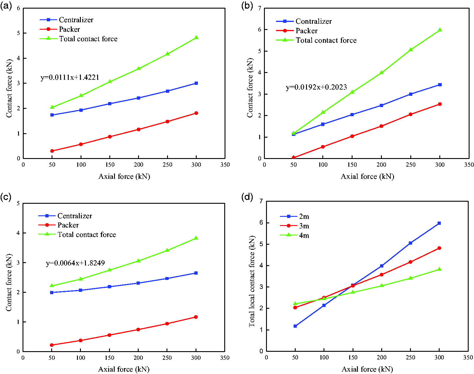
Contact forces under various distances between the packer and centralizers: (a) 2 m; (b) 3 m; (c) 4 m; and (d) total contact force under various distance.
Considering the actual sizes of the wellbore and the completion string, the curves in Figure 5 indicate that under the support of the centralizer, the packer will leave from the lower side of the borehole and touch the upper side, and the contact force will increase with the axial force. The local total contact force is composed of the support force of the centralizer and the contact force on the packer with the upper wellbore, and the total contact force increases approximately linearly with the incensement of the axial force. When the local drag is small, the total contact force will decrease when the centralizers are placed near the packer. Conversely, if the wellbore condition is poor and the local drag is high, the total contact force can be reduced by increasing the distance between the packer and the centralizers and reducing the centralizer quantity, so the completion string can be more easily run into the bottom hole.
Under the same axial force, the contact force between the packer and the wellbore will be greater when centralizers are installed in the completion string than without centralizers. This result is consistent with the actual tripping operation of the completion string in well sites, so the fracture completion string is often without string centralizers. The following discussion is mainly focused on this situation.
Effect of microsteps or slots on local drags
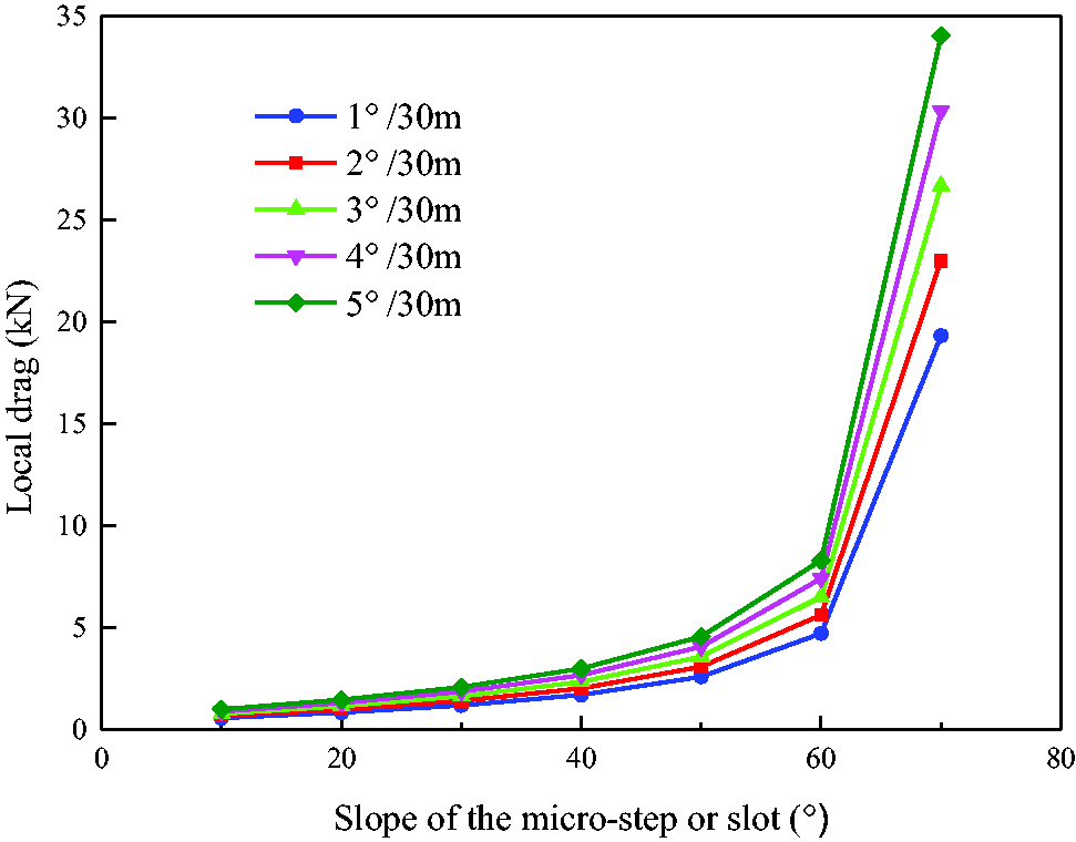
In the absence of microsteps and slots in the horizontal section, the relationship between the packer’s weight (w) and its axial force (Fd) can be obtained from Figure 4 as w = –0.0023Fd + 0.8713. To test the applicability of the formula when the horizontal section has microsteps or slots, the heights of the microsteps are assumed to be 1, 2 and 4 mm, and the contact force between the packer and the wellbore under various axial force is shown in Figure 6(a). Taking the friction coefficient between the microstep and the packer (μ) as 0.3, the relationship between the axial force and the local drags of the packer at the microstep under different slopes can be obtained as shown in Figure 6(b).
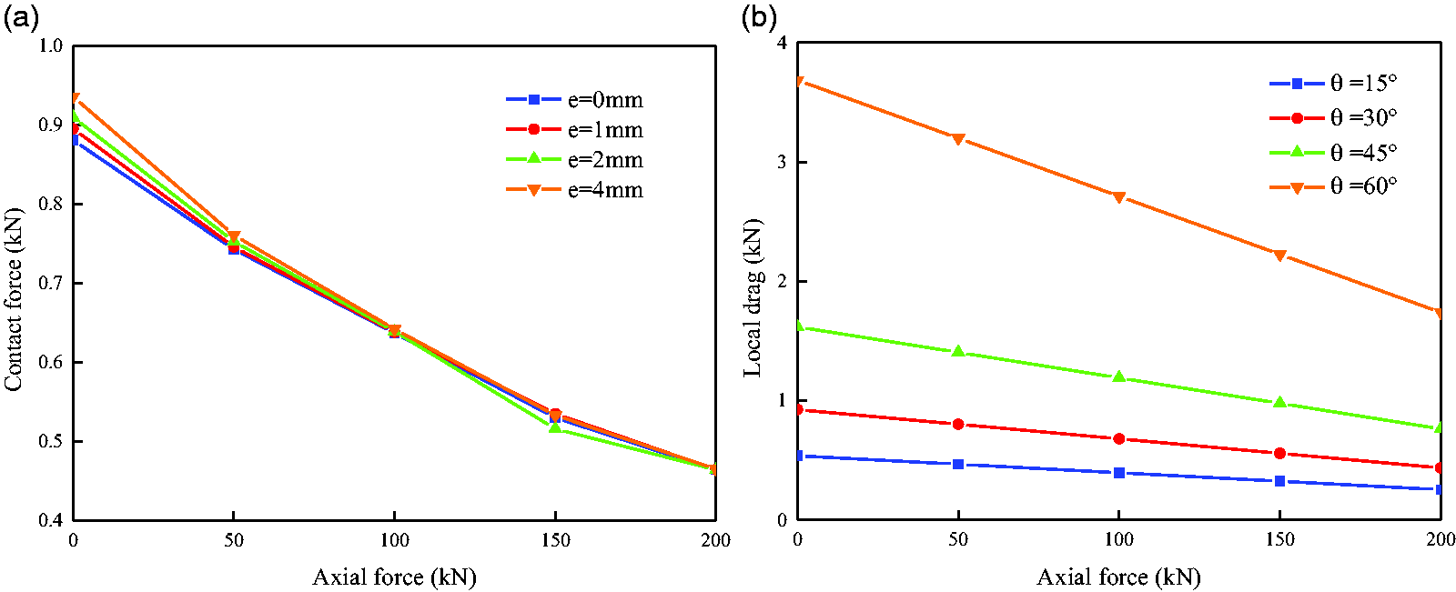
The contact force and the local drag of the packer V.S. axial forces (a) contact forces of the packer on the wellbore with various microstep heights; (b) local drags of the packer under different microstep slopes.
Figure 6(a) shows that the microstep height (e) has an influence on the contact force between the packer and the wellbore, but the influence is not obvious. Similarly, the slot depth has little effect on the contact force between the packer and the wellbore. Therefore, the formula above can be used for the packer’s contact force with the wellbore at the microsteps and slots. Figure 6(b) indicates that the sensitive factor of the local drag of the packer is not the microstep height nor the slot depth, but their slopes with the horizontal section. Under a certain slope, the local drag of the packer will decrease with the incensement of the axial force. This phenomenon also explains why the rapid reduction of the hook load to increase the axial force of the string can make it pass through some horizontal section with severe drag smoothly.
If the microstep slope is changed within a certain range, then the local drags of the packer at the microstep under different axial forces can be obtained as shown in Figure 7.
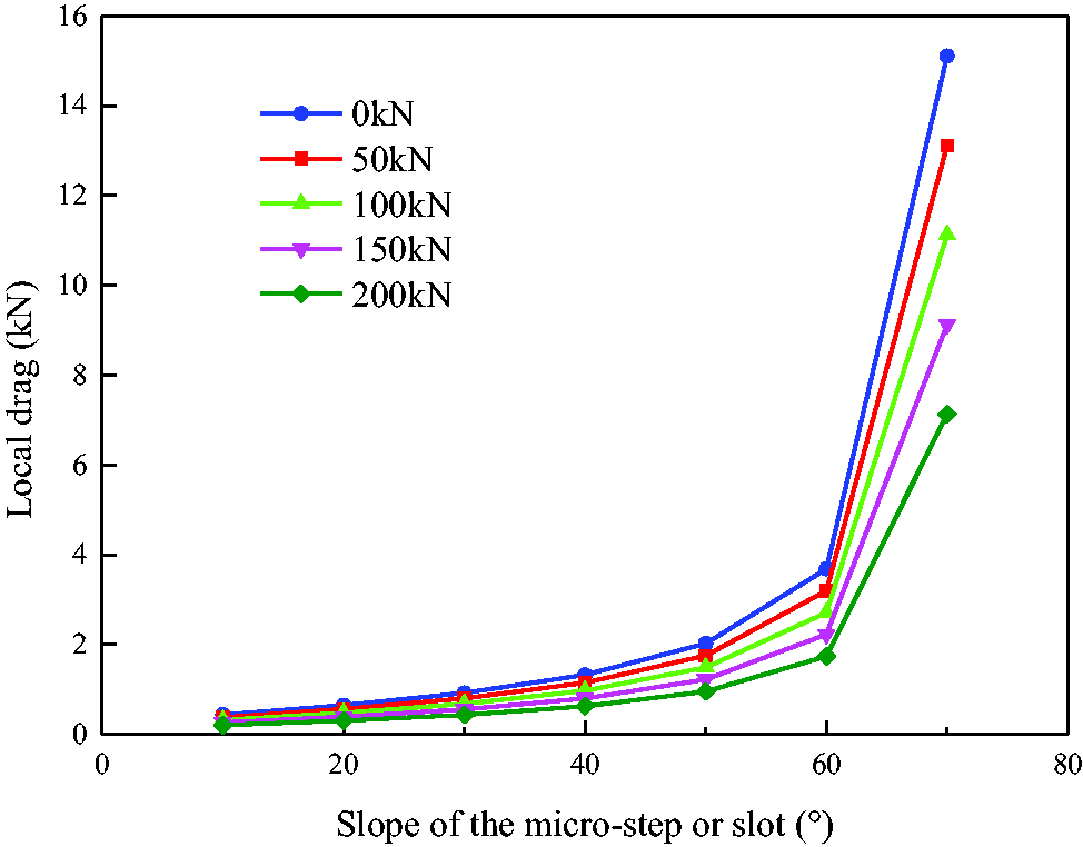
Local drags of the packer at microsteps under different axial forces.
If the axial force of the packer is constant, then the local drag at the microstep or slot will increase with the incensement of the slope. The local drag of the packer at the microstep or slot with a slight slope can be ignored and will suddenly increase when the slope exceeds 60°, and the completion string may even locked up. Therefore, it is necessary to fully condition the borehole before the completion string trips in the horizontal well (Wang et al., 2015; Zhou et al., 2016). In severe cases, a reasonable lead angle is also designed in the front of the packer to reduce its slope with microsteps or slots in the horizontal section, thereby reducing the local drag of the completion string during tripping into the horizontal section.
Effect of dogleg severities on local drags
Assuming that the axial force of the packer is 100 kN, the height of the microstep in the wellbore is 0 (without microsteps), 2 and 4 mm, and the local dogleg severity are 1°/30 m, 2°/30 m, 3°/30 m, 4°/30 m and 5°/30 m, the contact force results between the packer and the borehole are shown in Figure 8.
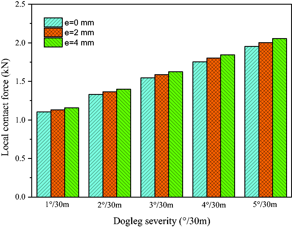
Contact forces between the packer and the borehole under different dogleg severities and microstep heights.
The comparison of the above calculation results shows that the contact force between the packer and the borehole is more affected by the borehole curvature than by the microstep height. The change of the contact force (Ns) between the packer and the well borehole will the variation of the wellbore curvature (К) can be regressed as follows:


Taking μ = 0.3, e = 4mm, and Fd = 100 kN, the calculation results of the local drag of the packer affected by the microstep slope in the horizontal section with different curvatures are shown in Figure 9.
Local drags of the packer affected by the microstep slopes and curvatures.
Under the same microstep height and axial force, the local drag of the packer will increase with the dogleg severity, but the increase will not be obvious, which also verifies that the local sticking phenomenon of the packer is not caused by the dogleg severity. Under a certain wellbore curvature, the local drag of the packer will increase with the slope. When the slope of the step exceeds 60°, the local drag will increase suddenly. Therefore, when the packer is in a horizontal section with both wellbore curvature and microsteps, the sensitive factor of its local drag is not the wellbore curvature but the slope of the microsteps. To create a smooth long horizontal section that is benefit for the completing string tripping, RSS (rotary steering system) is recommended as the directional drilling tool in horizontal wells (Zhang et al., 2018; Zhang and Di, 2000).
Effect of borehole shrinkage and enlargement on local drags
Local intervals with borehole shrinkage and enlargement
In many cases, the borehole diameter is irregular and the borehole enlargement occurs in some intervals due to collapse or borehole shrinkage in others due to the formation creep or mud cake. If the borehole enlargement or shrinkage occurs in short intervals only, then microsteps will naturally form between these irregular intervals and their transition with normal intervals. Under these circumstances, the local drag of the packer at the borehole shrinkage and enlargement is the same as that at the microsteps or slots, which has been discussed above. Therefore, only the effect of the borehole shrinkage and enlargement on the contact force between the packer and the wellbore must be studied.
Let the bit size be 152.4 mm and the outside diameters of the completion string and the packers be 114.3 and 143 mm, respectively. If the influence of rubber sleeve deformation is ignored, then the theoretical minimum wellbore diameter that the packer can pass through is 143 mm, and the corresponding borehole shrinkage rate is 6.16%. When the enlarged borehole diameter is 181.1 mm (borehole enlargement rate is 18.83%), its radius difference with the normal caliper is 14.35 mm, which is the same as the radius difference between the packer and the completion string. Thus, the packer will not touch the bottom side of the borehole, which is equivalent to the situation without packers in the completion string. To maintain data integrity, the packer is assumed to be in contact with the wellbore in the following calculation.
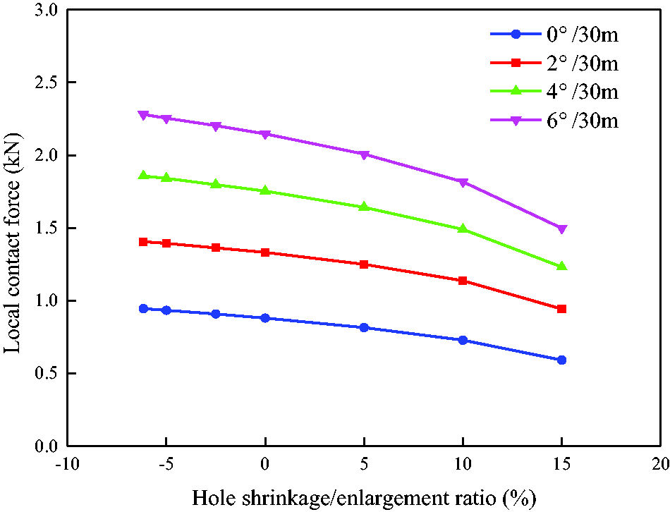
When the axial force is 100 kN, the contact force between the packer and the wellbore under different dogleg severities is shown in Figure 10, where a negative value represents the borehole shrinkage rate and a positive value represents the borehole enlargement rate.
Effect of borehole shrinkage and enlargement on the contact force between the packer and the wellbore under different curvatures.
The calculation results show that the contact force between the packer and the borehole decreases with the increase of the borehole diameter regardless of the borehole curvatures. Under a certain borehole diameter, the contact force will increase with the increase of dogleg severity. In general, the borehole shrinkage and enlargement of local intervals have little effect on the contact force between the packer and the wellbore. The wiper trip operation should be done if large drags exist at most places of the mud logging curve during drill pipe tripping out of hole.
Longer intervals with borehole shrinkage and enlargement
If the packer is located in a horizontal section with a long shrinkage or enlargement interval, that is, an entire interval with as overall borehole shrinkage or enlargement, then the packer in this interval is the same as that in the interval with a normal caliper. Obviously, the contact force between the packer and the borehole is unaffected by the borehole shrinkage or enlargement of the horizontal section with different dogleg severities.
Effect of cuttings on local drags
If some of the cuttings are left in the horizontal section, then an additional drag will exist in the completion string with packers during the tripping-in process. The difference in size of the downhole cuttings will have a different effect on the local drag of the packers. When the cuttings are small, the local drag will vary with the quantity of cuttings. If the wellbore has few cuttings, then cuttings will not fill the annular space between the wellbore and the packer, but it will be removed and accumulated by packers during the string running process. In this case, the packer’s local drag caused by the cuttings can hardly affect the string tripping-in operation, and this scenario is equivalent to the case in which the packer’s weight increases. The results of some lab tests verify that the rolling effect of few cuttings attached to the lower side of the horizontal hole may even reduce the local drag of the packer, which is very helpful in tripping-in the string (Liang et al., 2020).
If the wellbore has many cuttings with an accumulation effect in the borehole, then the local drag of the packers will be similar to that in the borehole with shrinkage. Then, the situation with few downhole cuttings can be obtained by circulating the drilling fluid or other technical measures. When the borehole is unstable or cave-in occurs, the effective diameter of the cuttings is very likely to be larger than the annular space between the packers and the wellbore, so the packers maybe stuck and the string cannot be tripped-in. In this case, the local drag varies with the axial force. The above qualitative analysis indicates that the influence of cuttings on local drag is difficult to study with quantitative methods. In practices, some special tools such as the cuttings bed destructor are highly recommend with sufficient circulating time and enhanced parameters, such as high flow rate of the drilling fluid and the rotation speed of the drill string (Denney, 2008; Ofei and Yaaqob, 2019), that can eliminate cuttings effectively. In addition, some special materials were also developed and used during the drilling fluid circulation to create a clean borehole, such as low density polyethylene beads (Yeu et al., 2019).
Conclusions
The sticking mechanical mechanism of the completion string illustrates that the local drag of packers can be created by slots or microsteps, dogleg severity, borehole enlargement or shrinkage, and downhole cuttings, which can affect the completion string’s tripping result in the horizontal section. It is verified that the local drag of the completion string can be magnified during its upward transmission in the horizontal well. The amplification effect is more obvious when picking-up than tripping-in the string. The greater local drag and the deeper stuck point are, the more obvious amplification effect is. If centralizers are not added in the completion string in the horizontal section, then the packer touches the lower side of the wellbore, and the contact force will decrease as the axial force increases. If centralizers are added, then the packer touches the upper side, and the contact force increases linearly with the incensement of the axial force. Under the same axial force, the contact force is larger when the completion string with centralizers than without them. The slopes of microsteps or slots affect more on local drags of packers than the effects of microsteps’s height and slots’ depth. The local drags increase with these slopes, rapidly increase when the slopes exceed 60°. The local drags increase slightly with the dogleg severity and decrease slowly with the borehole diameter, but the drags don’t change in the long interval with shrinkage or enlargement. Local drags caused by downhole cuttings vary with cuttings quantities.
Footnotes
Declaration of conflicting interests
The author(s) declared no potential conflicts of interest with respect to the research, authorship, and/or publication of this article.
Funding
The author(s) disclosed receipt of the following financial support for the research, authorship, and/or publication of this article: This work is financially supported by National Science and Technology Major Project (2017ZX05030-004).