
Abstract
A novel method named the needle increasing flow rate method (NIFRM) is proposed to measure the excessively low gas flow rates of extraction boreholes in coal mines. The main idea of the NIFRM is that when the flow rate of a branch extraction pipe of the borehole is lower than the minimum measurable flow rate of the gas extraction analyzer, a needle can be inserted into the branch extraction pipe to allow some air from the roadway to rush into the branch extraction pipe to increase the flow rate temporarily; then the gas parameters are measured and calculated successfully. To verify the rationality of this method and further optimize its parameters, the software FLUENT is applied to conduct a numerical simulation. The numerical simulation results show that the methane concentration will reach a satisfying equilibrium quickly after the air is introduced into the branch extraction pipe. The range and standard deviation of the methane concentration at 1.0 m downstream of the needle are 0.05% and 0.01%, respectively. The pressure difference between the inlet and outlet of the model is less than 10 Pa, indicating that almost all of the negative pressure of the gas extraction in the main extraction pipe is transmitted to the deep part of the branch extraction pipe. From the numerical simulation results, it is safe to say that the negative effect of the increasing flow rate is completely negligible by inserting the needle in the gas extraction system. Lastly, the NIFRM was applied to study the influence of coal seam permeability anisotropy on gas extraction in a coal mine, and the method was further verified.
Keywords
Introduction
Coalbed gas (mainly methane), associated with coal bodies, is abundantly enriched in coal seams in many coal mines (Iverach et al., 2015). However, the high gas content in coal seams can pose a serious threat to miner safety and coal production (Busch and Gensterblum, 2011; Clarkson and Salmachi, 2017; Wang et al., 2018). The gas extraction of a coal seam is an effective method to exploit methane resources but also to control its disasters (Bustin and Clarkson, 1998; Clarkson and Salmachi, 2017, Wang et al., 2018). Coal seam gas extraction is performed by constructing a number of boreholes in the coal seams, inserting the branch extraction pipes into the boreholes, and then sealing the boreholes. Subsequently, the branch extraction pipes are connected with the main extraction pipes of the extraction system of a coal mine. The extraction system extracts the gas from coal seams over time, thus reducing the gas content in the coal seams (Dong et al., 2017; Whittles et al., 2007).
To monitor the operation status of a gas extraction system in underground mines, it is a basic task to measure the gas extraction parameters. The gas extraction parameters of the gas extraction system can be subdivided into three levels: extraction parameters of the whole mine, extraction parameters of a working face and extraction parameters of a single borehole. The most important parameters of a gas extraction system are the gas flow rate, methane concentration, temperature, negative pressure of gas extraction, etc. (Qin et al., 2015; Szlazak et al., 2014; Zhou et al., 2014). Thereafter, the pure methane flow rate can be obtained by the multiplication of the gas flow rate and the methane concentration. The measurement of the gas flow rate of a single borehole is of great significance (Gatnar and Tor, 2003; Lu et al., 2009; Zou et al., 2014). After knowing the gas flow rate of a particular borehole, the construction quality and sealing quality of each borehole can be assessed, and information about special tectonics in the region of a borehole can be determined; the gas extraction technology can be analyzed by combining the single borehole flow rate with the phenomena during the drilling of the borehole. Additionally, the single borehole flow rate, in some cases, is also the basic parameter for calculating the gas flow attenuation coefficient and the permeability of the coal seams (Durucan and Shi, 2009; Fu et al., 2009; Huy et al., 2010; Zhao et al., 2012).
There are various flowmeters classified by operation principles, such as differential pressure flowmeters, electromagnetic flowmeters, turbine flowmeters, and acoustic flowmeters (Dong et al., 2018; Fatykhov and Bagautdinov, 2005; Lynnworth and Liu, 2006; Zhao et al., 2016). However, for most of them, the gas volume flowing through the flowmeter is measured by sampling the flow velocity at a selected point and multiplying the cross-sectional area of the pipe. The working principle of a flowmeter is that when gas flows through a flowmeter, it causes differential pressure or differential time or something similar, which can be detected. When the velocity, i.e. the flow rate, is too low, these parameters cannot be detected. With the limitations of technology and the harsh field environment of coal mines, each multi-parameter gas extraction analyzer, which is available on the market to measure the gas extraction parameters in coal mines, has a minimum measurable flow rate, Q4. For the sake of efficiency, multi-parameter gas extraction analyzers are used widely in coal mines (Jiang et al., 2017). There are a built-in flowmeter and some other kinds of sensors in a multi-parameter gas extraction analyzer, so it has the capacity to measure the gas flow rate, methane concentration, temperature, and negative pressure at the same time. A multi-parameter gas extraction analyzer also has a minimum measurable flow rate (Azevedo et al., 2013; Clarke and Ghaoud, 2003).
In some situations, the gas flow rate in a single extraction branch pipe is lower than the minimum measurable flow rate, with the result that the gas flow rate cannot be determined, and the pure methane flow rate also cannot be calculated (Hu et al., 2015; Keim et al., 2011; Su et al., 2011). At present, the commonly used flow rate measurement method in mines is as follows. The numbers of extraction branch pipes are gathered to an extraction main pipe; when the total flow rate of the main pipe is larger than the minimum measurable flow rate of the flowmeter, the total flow rate of all the boreholes is measured, and then the indirect determination of gas extraction flow rate of a particular single borehole can be conducted by means of the average method or the difference value method. Nevertheless, these methods are complicated and are accompanied by rather low accuracy.
To counter this problem, this paper presents a method called the needle increasing flow rate method (NIFRM) to measure the gas flow low-rate of a single borehole. The general idea of the NIFRM is to introduce some air from the roadway to the branch extraction pipes by a needle inserted into the branch extraction pipe to increase the gas flow rate temporarily, and if the increased gas flow is greater than the minimum measurable flow rate of the multi-parameter gas extraction analyzer, then the flow rate is computed easily.
According to the theory of fluid mechanics, this paper designs the arrangement of the NIFRM by theoretical analysis and numerical simulation and verifies it by a field test.
Overview of the method
Measuring method
The determination of the gas extraction parameters of single boreholes generally involves the measurement of many boreholes with a wide distribution in the roadways (Karacan et al., 2007; Lin et al., 2015). Therefore, the analyzer should be a portable device. A multi-parameter gas extraction analyzer (hereinafter referred to as “gas extraction analyzer”) is widely used in coal mines in China and can satisfy the requirement. This gas extraction analyzer has excellent performance among similar analyzers. In practical applications, we find that its minimum measurable flow rate, Q4, is 0.04 m3/min, and other parameter precisions, such as measurements of methane concentration and negative pressure, are suitable to be evaluated by the gas extraction system. The value of 0.04 m3/min is obtained and confirmed through much effort in the coal mine. For a normal borehole, we can block the gas flow and change the degree of blockage, and we find that the gas extraction analyzer only displays flow values which are greater than 0.04 m3/min. After a significant number of calculations of the methane concentration and the flowrate, we are sure of the value. Of course, it can be 0.039 or 0.041 m3/min, whereas the fluctuation of the value does not affect the application of NIFRM in this paper.
This paper explains the NIFRM to measure the gas flow rate of a single borehole by taking the application of this gas extraction analyzer as an example. However, this method is not limited to any particular device. As illustrated in Figure 1(a), the gas extraction analyzer includes a main body, a connector, and several flow-guide tubes. The flow-guide tube is a simple short tube with some holes on it, designed to fit the connector. The flow-guide tubes are installed on the branch extraction pipes. For most of the time, the holes are blocked, and the extracted gas flows in the tube. During the measurement, the probes of the connector are inserted in the flow-guide tube through the holes. Each borehole needs to be equipped with one flow-guide tube when it is connected to the gas extraction system. The main body of the gas extraction analyzer and the connector are linked by a data line, and they can be transported by a single person. When the parameters are to be measured, the main body of the gas extraction analyzer is turned on, the flow-guide tube connector is connected to the flow-guide tube, and the main body displays and stores the measured parameters. The problem is that when the gas flow rate in the extraction branch pipe (i.e., the gas flow rate of a single borehole) is lower than the minimum measurable flow rate, the gas flow rate is displayed as zero, and the methane concentration and negative pressure are displayed normally, which are the common features of such analyzers.
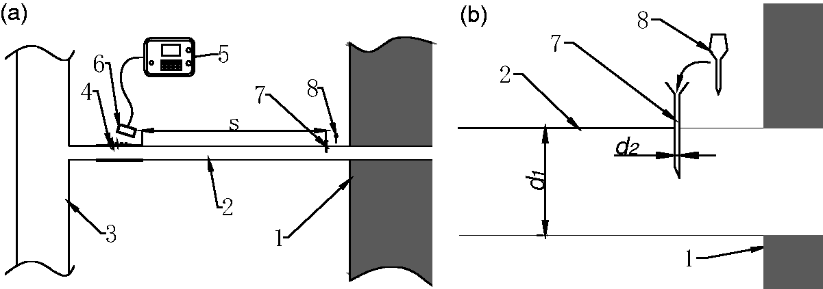
Schematic diagram of the needle increasing flow rate method: (a) the overall sketch; (b) the partial schematic diagram in the vicinity of the needle. 1 – coal wall, 2 – the branch extraction pipe, 3 – the main extraction pipe, 4 – the flow-guide tube, 5 – the main body of the gas extraction analyzer, 6 – the connector, 7 – the needle, 8 – the rubber plug.
The needle we use is a small stainless-steel hollow pipe with a mouth like a dispensing needle. The length of the needle we use is about 4 cm. When used, the needle tip is in the branch extraction pipe and the mouth is in the roadway.
Measurement steps of the NIFRM
When the flow rate of the branch extraction pipe is too small for the flow rate to be read, a needle is inserted into the branch extraction pipe; the needle is located between the roadside and the flow-guide tube, as shown schematically in Figure 1. The inner diameter of the needle is d2, and the distance between the needle and the flow-guide tube is s. Pressed by the differential pressure between the roadway and the flow-guide tube, the air in the roadway will flow into the flow-guide tube. Then the flow rate in the flow-guide tube is greater than the minimum measurable flow rate of the gas extraction analyzer and the flow rate can be determined. The detailed operation steps of this method are as follows:
Connect the flow-guide tube and the connector, and record the original methane concentration C1 in the branch extraction pipe. Insert the needle into the branch extraction pipe perpendicular to the wall of the pipe. The needle is between the flow-guide tube and the coal wall. Pull out the rubber plug on the needle. After the flow rate and methane concentration are stable, record the flow rate Q2 and the methane concentration C2. Block the needle with the soft rubber plug again and leave the needle and soft rubber plug on the flow-guide tube for future use.
Theoretical analysis
The application of the NIFRM is based on two assumptions: (1) The amount of methane introduced into the branch extraction pipe by the needle is small and negligible compared with the original flow in the branch extraction pipe. (2) When increasing the flow rate by the NIFRM, the pressure drop in the branch extraction pipe, which may lead to a decrease of the original flow rate, is small enough to be neglected.
The air flow rate introduced into the branch extraction pipe is of the same order of magnitude as that in the original branch extraction pipe, usually within two or three times. Moreover, for the roadways related to this paper, Coal Mine Safety Regulation of China states that: “the maximum allowable concentration of methane is 1%”. One percent is a red line. In most coal mines, there is a more stringent requirement, generally 0.5%. In our field test, the methane concentration is less than 0.2% for the most time. For the branch extraction pipe that will adopt NIFRM, the original methane concentration in the branch extraction pipe is rather high and can reach hundreds of times of that in the air of the roadway (Cheng et al., 2011; Karacan et al., 2011; Zhang et al., 2015). The implication of the previous sentence is that when the borehole is poorly sealed and air leakage exists, the original flow in the branch extraction pipe will be relatively high; thus, in these conditions it is not necessary to use the NIFRM. In other words, all the boreholes involved in the NIFRM method are characteristic of a high methane concentration and a low flow rate. Through the above analysis, it can be concluded that the first assumption holds. The second assumption will be validated in the numerical calculation part and the field test part to be discussed below.
By allowing the roadway air to the gas extraction system, the methane concentration is reduced. To prevent the methane/air mixture explosion hazard, the Coal Mine Safety Regulation of China states: “When the coal mine gas drainage pump is dry-type, the methane concentration of extracted gas cannot less than 25%.” However, nearly all the coal mines (including the field test coal mine in this paper) in China adopt wet-type pumps. In addition, application of the NIFRM on the boreholes is conducted one by one, and normally, each takes no more than 2 min. After the operation, the needle is blocked. The mine air flows into a branch extraction pipe, and then a large number of branch extraction pipes flow into a main extraction pipe. Compared with the flow rate of a main extraction pipe, the flow rate of a needle is too small to cause a large change in the methane concentration in a main extraction pipe.
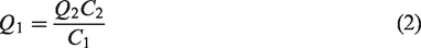
According to the law of mass conservation (Didier et al., 2000), the pure gas flow rate in the branch extraction pipe remains unchanged before and after introducing the roadway air, and it can be expressed as


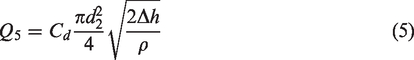
The air in the roadway flowing into the branch extraction pipe is due to the differential pressure between the roadway and the flow-guide tube, and the needle acts as a nozzle. Therefore, according to fluid mechanics theory, the air flow rate Q5 flowing through the needle can be expressed as
Equation (5) can be rearranged and written as
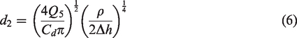
The inner diameter of the needle can be calculated by equation (6). It is worth noting that Q5, Δh and ρ are not constants but change with different boreholes and different running times of the gas extraction (Parra et al., 2006). However, this situation will not affect the accuracy of the method because the calculations of Q1 and q3 do not directly use the values of Q5, Δh and ρ. d2 obtained by equation (6) acts as the guiding size of the needle. The principle of determining the value of d2 is to minimize the influence of the increasing flow rate in the extraction branch pipe on the gas extraction system. To ensure this principle, d2 should be as small as possible under the premise of Q2 > Q4. It is easy to know that Q2 is greater than Q5. In our practical computation of d2 in equation (6), Q5 = Q4, Cd = 0.6 and ρ = 1.29 kg/m3, and as a result, the obtained d2 is a conservative value that is slightly larger than needed, which ensures that the flow rate of all boreholes can be determined. The minimum measurable flow rate of the gas extraction analyzer used in a coal mine is a constant value. Therefore, one uniform size of needle can be used in all gas extraction operation conditions of the mine, which is greatly helpful for application of the NIFRM.
To ensure that the air introduced into the branch extraction pipe has been fully mixed with the original air in the branch extraction pipe before methane concentration measurement, the distance between the needle and the flow-guide tubes should not be too small. In this case, 1 m is an appropriate distance, and the value will be verified in the numerical simulation part.t is the time needed for the mixture of gas in the branch extraction pipe to flow from the needle to the flow-guide tube. Therefore, the time interval between pulling out the rubber plug and preparing to read the values displayed by the gas extraction analyzer should be larger than t. t is expressed as
Numerical simulation
To verify the rationality of the NIFRM and to further optimize the parameters, the computational fluid dynamics software package FLUENT is used to simulate the whole process.
Control equations of methane-air mixture flow
All fluids conform to at least three conservation laws (Alazard, 2006): the law of mass conservation, the law of momentum conservation, and the law of energy conservation. Moreover, the fluid involved in this numerical simulation is a mixture of methane and air. In both the coal mine gas extraction system and software FLUENT, air can be treated as a whole with uniform physical parameters. When methane and air mix and interact with each other, in addition to the aforementioned three conservation laws, the law of components conservation must be confirmed for the flow in the branch extraction pipe (Kuhl et al., 2013). The governing equations of fluids are the mathematical expressions of these laws. The expressions of these laws are as follows:
Equation of continuity
The equation of continuity is the expression of the law of mass conservation in fluid mechanics, and it can be expressed as follows
2. Equation of momentum
The conservation of momentum means that the force acting on the microelement in a unit of time is equal to the momentum change rate in the microelement, and it can be expressed as follows
3. Equation of energy

The conservation of energy means that the increasing rate of energy in the microelement is equal to the sum of the heat flowing into the microelement and the work done by the surface force on the microelement per unit time. It can be expressed as follows
Equation of components conservation

The equation of components conservation indicates that the net diffusion flux and the net generation rate of a component in the mixed gas are equal to the changing rate of the component with time. The migration of the methane–air mixture is affected by two factors: one is convection, which is controlled by the flow of the mixture fluid, and the other is molecular diffusion, which is the diffusion effect of each component because of the differential concentration. Therefore, the equation of components conservation is also known as the convection–diffusion equation (Gupta and Zhang, 2000):

FLUENT model establishment
In this numerical simulation, the modeling parameters are obtained from a test borehole in the study, which is being used to research the influence of coal seam permeability anisotropy on gas extraction in a coal mine. The negative pressure of gas extraction is 10 KPa; the inner diameter of the branch extraction pipe is 0.06 m; the original methane concentration is 73%; the original gas flow rate of the single borehole is 0.02 m3/min, which is less than the minimum measurable flow rate of the gas extraction analyzer, 0.04 m3/min; the original flow velocity in the branch extraction pipe is 0.13 m/s according to the gas flow rate. In the calculation of d2 in equation (6), Q5 is 0.04 m3/min, Cd is 0.6, ρ is 1.29 kg/m3, and Δh is 10,000 Pa, so d2 is 3.3 mm.
As shown in Figure 2, the ICEM software in ANSYS WORKBENCH is used to establish the 3D geometric model and mesh it. The total length of the branch extraction model is 2.3 m. The right side of the branch extraction is connected to the deep coal seam, and the left side is the direction to the main extraction pipe. The needle is at the position of 0.3 m from the right end of the geometry. The distance from the inner wall of the pipe to the needle outlet is 2 cm. To reduce the consumption of computer resources in the numerical simulation, two kinds of grids are used to mesh the geometry (Vinchurkar and Longest, 2008). The needle and its left and right parts within 0.05 m are meshed by unstructured tetrahedral grids, and the rest are meshed by structured hexahedral grids. The total number of cells is 1,588,942.
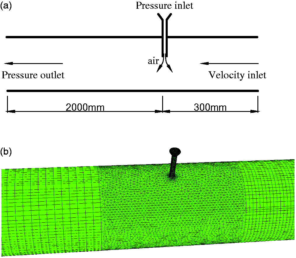
Geometry and the mesh of the numerical model: (a) schematic illustration of the model; (b) mesh grids in the vicinity of the needle.
The species transport model in FLUENT is able to simulate the mixing and transport process of multicomponent gas flow, so it is suitable for the flow process of the air in the roadway flow into the extraction branch pipe. The right side of the model is set to be the velocity inlet with a speed of 1.3 m/s and the left side is set to be the pressure outlet with a pressure of −10,000 Pa. The entrance of the needle is set as the pressure inlet with a pressure of 0 Pa. The density of methane and air is modeled as an ideal gas.
Simulation results
Figure 3 shows the numerically simulated velocity field in the branch extraction pipe. Under the effect of the negative pressure of gas extraction, the air from the roadway rushes into the branch extraction pipe through the needle at a high velocity, and the average velocity in the needle is 115.4 m/s. The high-speed air has a certain influence on the upstream and downstream flow field in the branch extraction pipe, and the influence scope to the upstream is approximately 0.15 m. The air flow Q5 introduced by the needle is 0.055 m3/min, which is greater than the minimum measurable flow rate of the gas extraction analyzer; therefore, it is in accordance with the theoretical calculation, and the designed size of the needle satisfies the application demand in the coal mine. The difference between Q5 and Q4 is due to the conservative flow coefficient Cd, which is chosen when calculating d2.
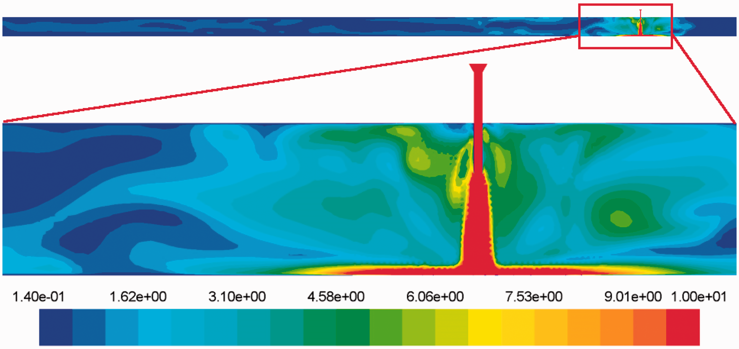
Velocity field in the branch extraction pipe (m/s).
Equation (5) can be transformed as
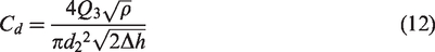
Then, the actual discharge coefficient of the needle is 0.86, obtained by equation (12).
Figure 4 shows the numerical simulation of the gas concentration field in the branch extraction pipe. Similar to the velocity field, the high-speed airflow changes the original flow pattern near the needle and the influence scope of the gas concentration involved approximately 0.15 m upstream.
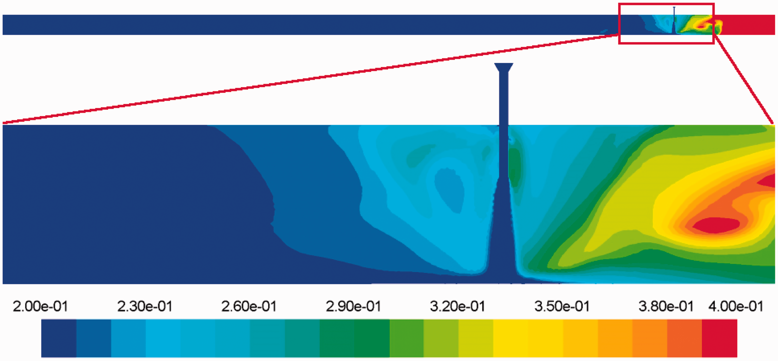
Methane concentration field in the branch extraction pipe (dimensionless).
Figure 5(a) to (d) shows the gas concentration fields of the sections of the branch extraction pipe at 0.4 m, 0.6 m, 0.8 m and 1.0 m downstream of the needle, respectively. It can be seen from the color bars that as the flow distance of the mixture gas downstream increases, the methane concentration distribution becomes gradually uniform. In this paper, the statistical term of the range and standard deviation are adopted to evaluate the methane concentration uniformity quantitatively. The range is the difference between the highest and the lowest methane concentration in the cross section of the branch extraction pipe. The standard deviation is obtained from 500 sample points in the cross section. The evaluation results and the fitting curves are shown in Figure (6). As the distance increases, the range and standard deviation decrease rapidly. The range and standard deviation are 0.05% and 0.01%, respectively, at a distance of 1.0 m, and both of them are much less than the methane concentration sensitivity of the gas extraction analyzer. Moreover, the distance of 1.0 m between the flow-guide tube and the needle is also very easy to achieve in practical applications.
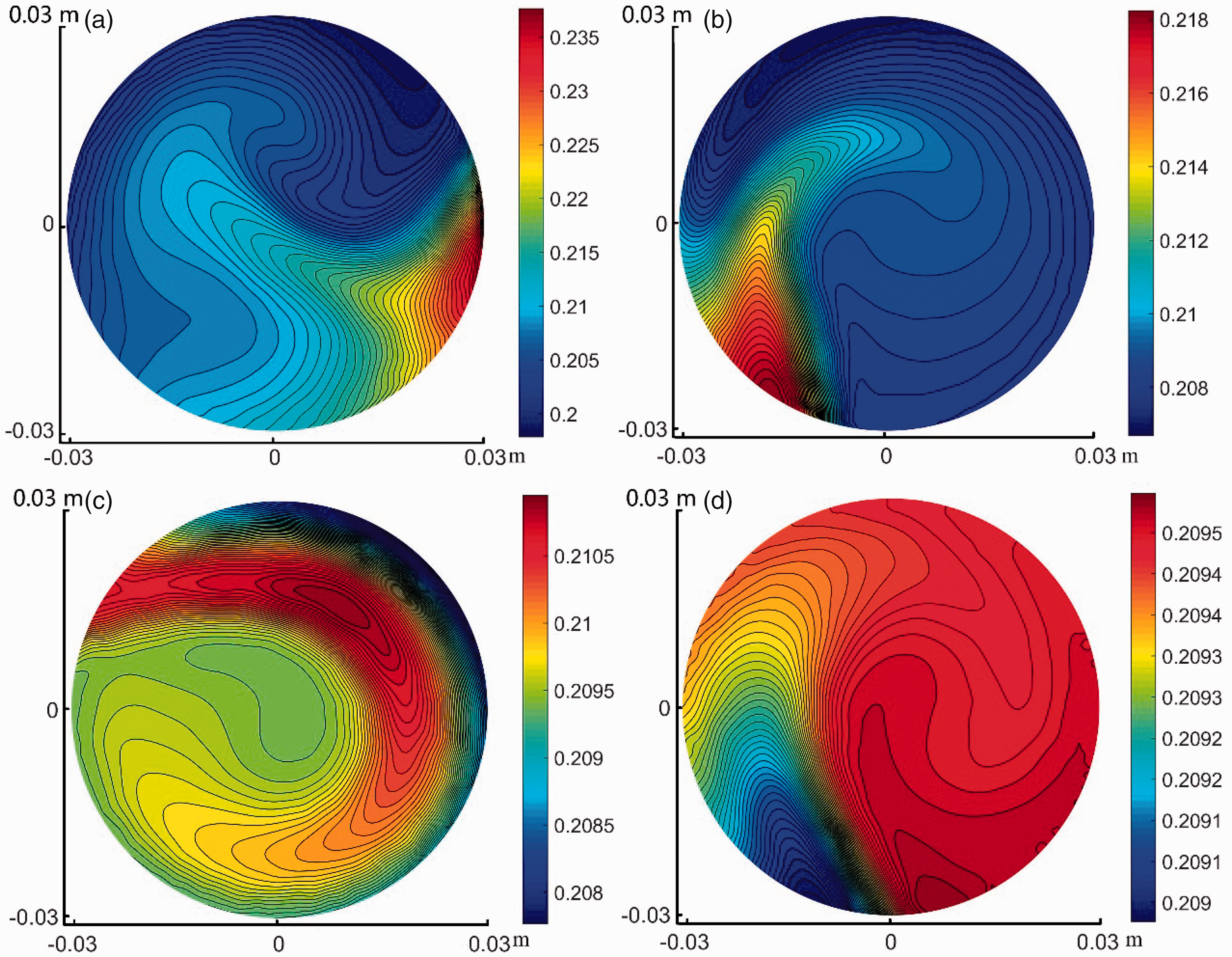
Methane concentration field downstream from the needle. (a) 0.4 m; (b) 0.6 m; (c) 0.8 m; (d) 1.0 m.
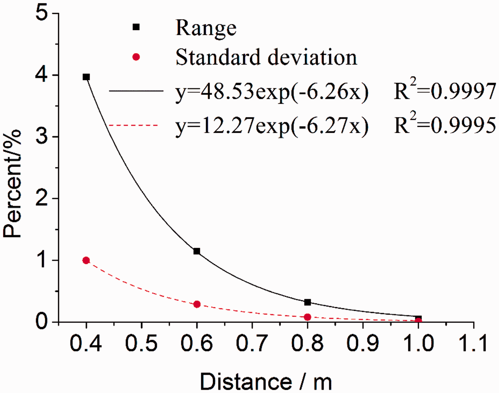
Fitting curves of range and standard deviation of the methane concentration.
The pressure of the inlet on the right and the outlet on the left in the simulated flow field is monitored, and the differential pressure between those two values is less than 10 Pa. The pressure drop of 10 Pa is related to both the needle and the flow resistance, and thus the pressure drop caused by the needle is smaller than 10 Pa. Considering that the negative pressure of the gas extraction is 10,000 Pa, the 10 Pa indicates that nearly all the negative pressure of the gas extraction in the extraction main pipe is transmitted to the deep portion of the branch extraction pipe. From the foregoing discussion, it is easy to conclude from the numerical simulation results that the negative effect of penetrating the needle on the branch extraction pipe is negligible and that the feasibility of NIFRM is well supported.
Field test
Field conditions
In the study of the influence of coal seam permeability anisotropy on the gas extraction in a coal seam (Wang et al., 2014), 45 boreholes were drilled in three test areas, with 15 boreholes in each area. The field test was carried out in the Xinjing coal mine in Yangquan city, Shanxi Province, PR China. All three areas did not undergo any increased permeability measurements, so the coal permeability was relatively low. The arrangements of the boreholes in the three test areas are similar to each other, and the arrangement of one test area is shown in Figure 7. All the test boreholes are drilled in the coal seams, with a length of 70 m and a diameter of 74 mm. The sealing length is 10 m. The boreholes are divided into five types by azimuth angles. Because the purpose of the test is to analyze and evaluate the effect of borehole orientation on gas extraction in a coal seam, the axes of the five borehole types and the coal wall have angles of 30°, 60°, 90°, 120° and 150°.
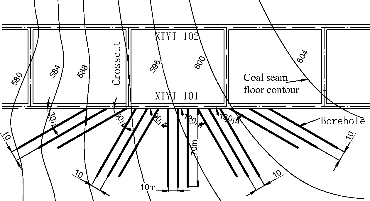
Schematic diagram of the borehole layout.
There are only three test boreholes for each type; thus, every borehole is important. To eliminate the significant influence of individual boreholes on the evaluation results, measuring the gas flow rate of a single borehole is particularly critical. Since the test areas are in virgin coal seams and the test boreholes are sealed well, the single original flow rates of more than 10 boreholes are less than the minimum measurable flow rate of the gas extraction analyzer. Ten boreholes take a large proportion of the total 45 boreholes. What is worse, the flow rate of other boreholes will also decrease over time.
Effect verification
The gas extraction parameters of the boreholes in the test are measured by the NIFRM. The model of the multi-parameter gas extraction analyzer in our field test is CJZ-70. When the flow rate of a borehole is very low, the needle is inserted at the position of approximately 1 m upstream of the flow-guide tube. Before and after removing the rubber plug, two sets of data are recorded. Then, the data are processed to obtain the actual original flow rate and methane concentration. The time required of the NIFRM for one borehole is only about 1 min longer than that of the normal boreholes. After the measurement is completed, the needle is left on the branch extraction pipe for next use directly.
To verify the correctness of the method, 10 boreholes are selected to do some additional work. Five of the boreholes, called Group 1, are used to check the influence of the inserted needle on the negative pressure of the gas extraction; the other five boreholes, called Group 2, are used to test the measurement accuracy of the flow rate.
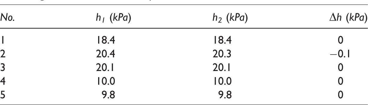
The flow rate of the five boreholes in Group 1 is less than the minimum measurable flow rate of the gas extraction analyzer. The unique feature of Group 1 is that the needle is inserted at the position of 1 m or more downstream (others are located upstream) of the flow-guide tubes when testing. The Group 1 boreholes are selected to confirm that the pressure drop induced by the inserted needle on the extraction system is small enough to be ignored. The pressure drop should be upstream of the needle because the coal seam is upstream of the needle. Thus, when the needles of Group 1 are set downstream of the flow-guide tubes, the flow-guide tubes can measure the pressure drop of the upstream of the needles. Before pulling out the rubber plug, the negative pressure of gas extraction h1 is measured in the boreholes before introducing the air flow from the roadway. Then, the negative pressure of gas extraction h2 is measured after removing the rubber plug. Δh denotes the change in the negative pressure of gas extraction before and after the increase of flow rate. Since the pressure resolution of the gas extraction analyzer is 0.1 KPa, it cannot be detected when the change of pressure is extremely small. It can be seen from Table 1 that the pressure change caused by the increasing flow is small, and therefore, the pressure drop caused by the NIMF can be neglected.
Change of the negative pressure of gas extraction before and after increasing the flow rate of Group 1.
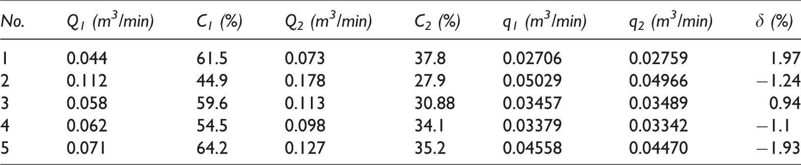
In Group 2, in order to prove that the pure methane flow rate before and after introducing the air into the branch extraction is constant, five boreholes are selected, whose original flow rates in the branch extraction pipes are slightly greater than the minimum measurable flow rate of the gas extraction analyzer. For the borehole with a low flow rate, there is no proper existing device to conduct the verification, so we have to select the boreholes with the greater flow rate. It is easy to conclude that the slightly greater flow rate will not truly weaken the verification of Group 2. q1 and q2 denote the pure methane flow rate before and after the flow increase, respectively, and δ represents the relative error of the two values. It can be concluded from Table 2 that the field test proves that the pure methane flow in the branch extraction pipe before and after the flow increase is almost unchanged, and the greatest absolute value of the relative error is 1.97%, which is completely acceptable for the gas extraction system in a coal mine. According to the pressure change from the numerical simulation part and that previously measured, it can be inferred that the relative errors are more likely to be the accuracy problem of the gas extraction analyzer, and it has nothing to do with the measurement method of NIFRM.
The measurement of the pure methane flow rate before and after increasing the flow of Group 2.
Conclusions
The needle increasing flow rate method is presented to measure the excessively low gas flow rates of boreholes. Despite the different locations of the boreholes and the running times of the gas extraction system, this method can work well with high accuracy assuming that the methane in mine air is neglected. Once the size of the needle is calculated properly, it can be used by all boreholes in a coal mine. The numerical simulation results show that at 1.0 m downstream of the needle, the methane concentration will reach a satisfying equilibrium. The pressure difference between the right and left of the numerical model is smaller than 10 Pa, which indicates that the pressure drop from introducing air into the branch extraction pipe is negligible. The field test also shows that the negative pressure of gas extraction all transmits to the deep part of the branch extraction pipe. Before and after increasing the flow rate by the needle, the pure methane flow rate is almost constant with a rather small relative error. According to the theoretical analysis, numerical simulation and field test, NIFRM is proved to be highly feasible and reliable. It can be adopted by nearly all boreholes affected by the problem of excessively low flow rate in a coal mine.
Footnotes
Declaration of conflicting interests
The author(s) declared no potential conflicts of interest with respect to the research, authorship, and/or publication of this article.
Funding
The author(s) disclosed receipt of the following financial support for the research, authorship, and/or publication of this article: This research is financially supported by the State Key Research Development Program of China (Grant Nos 2016YFC0801402, 2016YFC0600708), the National Natural Science Foundation of China (Grant Nos 51874314, 51604278, 51774292), the Open Funds of Hebei State Key Laboratory of Mine Disaster Prevention (Grant No. KJZH2017K02), the Fund of China Scholarship Council (CSC), the Yue Qi Distinguished Scholar Project, China University of Mining, Technology, Beijing, the Guizhou Science and Technology Support Program ([2017]2820).