
Abstract
The fault block hydrocarbon reservoirs developed by water flooding in Shengli Oilfield have entered into the period of high water cut and low oil recovery. The residual oil to be recovered is challenging by using the unidirectional water or gas displacement method in producing oil from the reservoirs because of water invasion or gas channeling. A novel method of bidirectional displacement with artificial nitrogen gas cap and edge water is presented to improve the oilfield development recovery efficiency. This novel method refers to the nitrogen gas injection at the top of the inclined reservoir and the edge water injection at the bottom of the reservoir simultaneously. The experiments of the sandpack model are performed to explain the benefits of nitrogen gas flooding and to evaluate quantitatively the production performance of the bidirectional displacement process. A numerical simulation technique based on the proposed method is employed to find out befitting reservoirs for implementation of this new novel method. The X48 inclined fault block hydrocarbon reservoir in Dongxin production area, Shengli Oilfield, is selected as the actual research block to verify the benefits of bidirectional displacement with artificial nitrogen gas cap and edge water. The results indicate that the oil recovery by bidirectional displacement of nitrogen gas injection in the X4841 injection well and edge water injection in the X48CXN9 injection well cooperatively is higher than that of unidirectional water flooding or gas flooding in the X4841 injection well. The oil recovery factor increases by 11.2% than that by the original water injection development in the X48CXN9 injection well. Another interesting finding in this work was that, for the oil recovery, an appropriate ratio relationship is established between the nitrogen injection rate and the water injection rate regardless of production rate.
Keywords
Introduction
More and more technologies or methods have been developed for enhanced oil recovery (EOR) and improved oil recovery (IOR), mainly like thermal recovery, chemical flooding, gas flooding, etc. Water flooding has already been very common for EOR/IOR in the worldwide and has become the leading technology of ultra-low permeability reservoirs in China. But the ultra-low permeability reservoirs generally have unsatisfactory characteristics of strong water sensitivity, poor infiltration, and serious heterogeneity, which prevent in the establishment of effective displacement pressure systems (Austad et al., 2005; Deng, 2002). Importantly, water fingering phenomenon around most of production wells frequently occurs because of long-term water injection.
As we all know, the oil recovery by water flooding might only reach 40%–60% of the original oil in place (OOIP) of conventional hydrocarbon reservoirs (Kantzas et al., 1988). After the oil reservoirs enter the high water cut stage, the water injected into reservoirs preferentially flows along large channels, which results in short water breakthrough time in production well (Ju et al., 2007). Although the production efficiency of water flooding is poor, these oilfields still have considerable developmental potentials. How to improve the recovery efficiency in the high water cut period has always been the concern of the oilfield workers and researchers. Gas injection is an attractive process to implement the shortcomings of water flooding, which can maintain reservoirs pressure and reduce stratum damage (Jia, 2006; Li et al., 2002). The main gas injection methods include CO2 flooding, nitrogen flooding and flue gas flooding (Chen and Reynolds, 2016; Ren et al., 2015).
CO2 flooding has been used for decades as an acceptable tertiary recovery method in the petroleum industry (Green and Willhite, 1998; Lake, 1989; Moritis, 2004; Orr and Taber, 1982), where water flooding is largely unsuccessful (Sahin et al., 2007, 2012). Depending on the characteristics of the reservoir fluid, the oil displacement process by carbon dioxide injection is classified in two ways. On the one hand, miscible or multi-contact miscible displacement process occurs above the minimum miscibility pressures (MMPs) (Bon et al., 2005; Emera and Sarma, 2005; Hamouda et al., 2018; Rezaei et al., 2013), in which there are more components interchange (Emadi et al., 2013; Hamdi and Awang, 2013; Hamdi et al., 2014). CO2 dissolution and stronger adsorption capacity lead to oil swelling, solution gas drive, and oil extraction (Liu et al., 2017; Sun et al., 2013, 2017). On the other hand, immiscible displacement occurs below the MMP, in which there are less components interchange or mixing zones between the injected gas and the reservoir fluids (Sahin et al., 2007). But the low viscosity and density of carbon dioxide result in gravity override and unbeneficial mobility ratio (Wang et al., 2017). Consequently, unstable displacement front advancement during CO2 flooding easily causes gas channeling.
Nitrogen (N2) injection has been used worldwide since the mid-1960s as a secondary or tertiary recovery method, which maintains pressure to enhance oil recovery in different lithological reservoirs (Bujanos et al., 2005; Sinanan and Budri, 2012; Wu et al., 2013). There are more benefits for nitrogen injection, for example, non-corrosive factor, availability of onsite nitrogen gas production, and lower production or operation cost by cryogenic air separation (Belhaj et al., 2013). Inert and non-corrosive nitrogen do not absorb on matrix surface of reservoir rock or alter the rock’s wettability in low-permeability reservoirs (Yu and Sheng, 2016). More production benefits of oilfield are attributed to nitrogen injection (Bujanos et al., 2005; Daltaban et al., 2008; Guzmann, 2014; Heucke, 2015). However, one of the main limitations of nitrogen flooding is the high-energy requirement for the cryogenic air separation process, which is used to produce nitrogen gas onsite (Heucke, 2015).
Flue gas injection for EOR received a great deal of attention in the 1960s (Barstow, 1973), but it had not been studied in detail. Recently, more in-site application in oilfields, like Shengli, Zhongyuan, Daqing or Jiangsu, has been carried out successfully, especially the flue gas-assisted steam flooding (Han et al., 2017; Li et al., 2017). Flue gas is industrial waste gas produced by the burning of fossil fuels. The main components of flue gas are 80%–85% of N2 and 15%–20% of CO2. Nitrogen gas has the capacity of increasing stratum energy and heat insulation, and carbon dioxide has the effect of dissolution, viscosity reduction and volume expansion (Perera et al., 2016; Wang and Li, 2002). But flue gas easily corrodes pipeline because of severe corrosive substances, which is regarded as an unavailable energy to improve oil recovery economically.
As we can see, gas channeling, poor displacement efficiency or high production costs frequently occur during immiscible displacement process, and consequently the ultimate recovery is not as high as we expected. In order to mitigate the shortcomings during gas flooding process, a method of bidirectional displacement with artificial nitrogen gas cap and edge water for EOR is presented to improve oilfield development efficiency. This method is roughly put forward in Shengli Oilfield, Sinopec, to prevent the fast pace of gas channeling and to increase the displacement efficiency. Whereas there is no causal analysis of the benefits of nitrogen gas flooding at the updip position of an inclined reservoir. Furthermore, there are no experimental works based on oilfield application of this displacement method.
There are six sections in this paper, the introduction and the content of the theoretical explanation are presented in the first and second section, respectively. Significantly, the third section shows the comparison tests in the sandpack physical model about the production performances. The screening criteria of reservoirs suited to this method for EOR and the application of the bidirectional displacement by using numerical simulation method at a pilot area in Shengli Oilfield are shown in the fourth section. In the fifth section, the results of experiments and numerical simulation process are presented. Lastly, the sixth section listed the principal findings drawn from this study as conclusions.
Mechanism explanation
In inclined reservoirs with low oil viscosity, immiscible displacement methods are ultilized by injection gas into the oil-bearing stratum. Gas flooding has high sweep efficiency (Guillot, 1995; Sinanan and Budri, 2012; Thomas, 2008), like nitrogen flooding, carbon dioxide flooding or flue gas flooding. Gas injection easily moves to the high position of the reservoirs to form the gas cap because of the resultant force. The gas cap is able to mitigate gas channeling, increase sweep efficiency and push the oil towards the production well. The resultant force of edge water injection inhibits the water fingering phenomenon along high-permeability zones and improves the sweep efficiency at the bottom position, as shown in Figure 1(a).
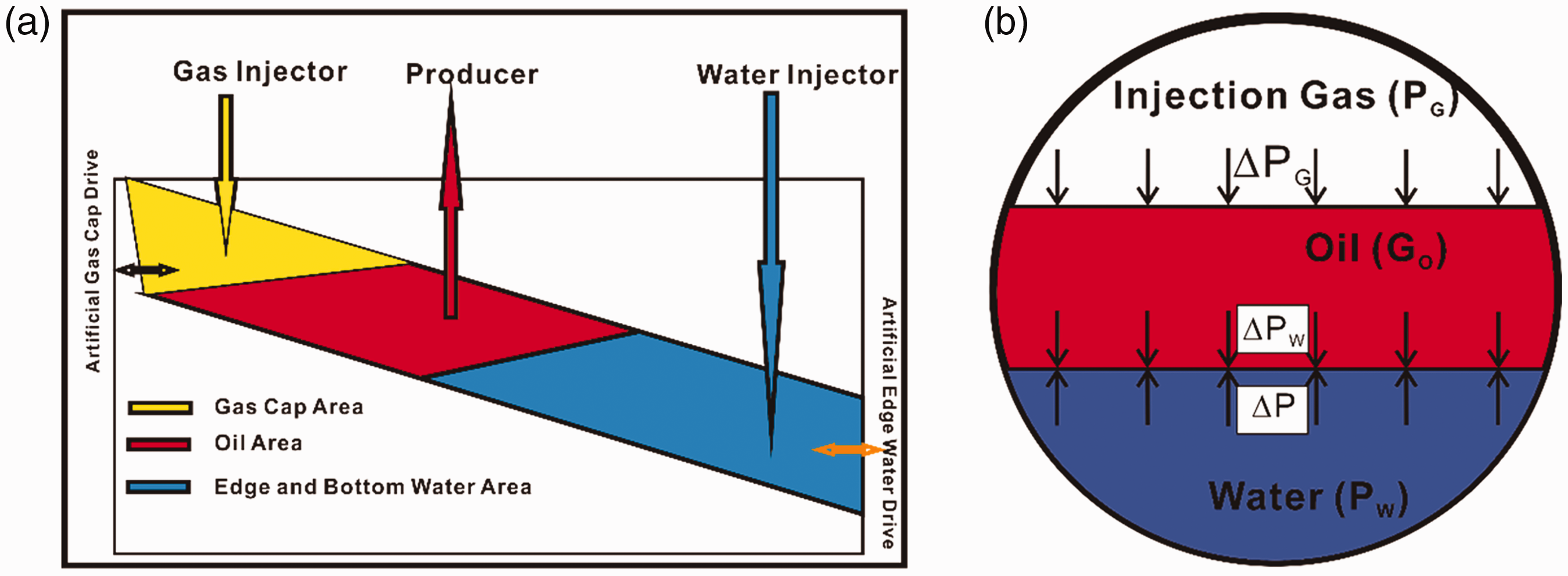
Mechanical schematic of bidirectional displacement process. (a) Three-phase fluid flow distribution in an inclined reservoir. (b) Mechanical mechanism of synergistic effect of edge water and gas cap (Qu et al., 2017).
Gas flooding is able to activate the remaining oil at the high position and edge water flooding keeps stable reservoir pressure system. But the migration interface easily appears unstable because of fluids variation or heterogeneous permeability. The stable oil–water or oil–gas interface generates synergistic effect, as shown in Figure 1(b). Three-phase gravity index (Nr) is able to describe the synergistic effect of gas and edge water injection during oil displacement process (Qu et al., 2017).
Three-phase gravity index is expressed in equation (1) as
Nr ≤ 1, the oil displacement process is stable, the synergistic effect of gas and edge water injection is effective; Nr > 1, the oil displacement is unstable, gas and water injection can easily form gas channeling and water fingering, respectively, opposing this synergistic effect.
Experiments
Experimental material
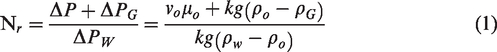
Combining the characterization of the reservoir and the maneuverability of the experimental model, we use polymethyl methacrylate to make an adjustable semi-transparent slab sandpack model. The sandpack model with the inside dimensions of 70 cm in length, 10 cm in width, and 3 cm in height, is bonded and sealed by epoxy resin. The wettability of the model is weak oil wet. The sand used in the model is 40 mesh quartz sand with good abrasion. The permeability of the sandpack model ranges from 2212 to 2588 mD and the porosity ranges from 36.18% to 38.56% are used in the experiments. Sockets are embedded in the different parts of the model according to the wells location designed in Figure 2(a). The locations of the real experimental designed wells are shown in Figure 2(b).
Locations of designed wells in sandpack model.
Experimental fluids
All experimental fluids were measured at atmospheric pressure and room temperature 25°C. The simulated oil is compounded with paraffin wax and kerosene in the proportion of 5:1, with the viscosity of 10 mPa·s. The gas injection includes nitrogen with a viscosity of 0.0199 mPa·s and CO2 with a viscosity of 0.0141 mPa·s. The flue gas with a viscosity of 0.0179 mPa·s consisted of 87.0% nitrogen and 13.0% carbon dioxide. The simulated water with analytic pure calcium chloride and sodium chloride at concentrations of 5000 mg/L and 21,000 mg/L, respectively, is used in the experiments. The density of the experimental water is 103 kg/m3 and the viscosity is 0.4563 mPa·s.
Experimental apparatus
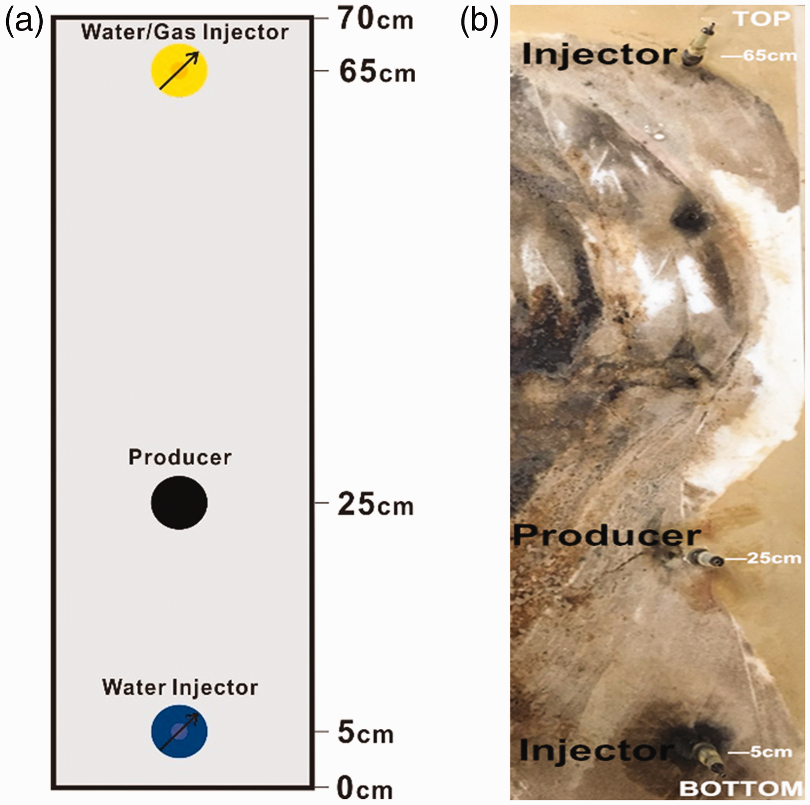
The experimental apparatus mainly consists of a semi-transparent slab sandpack model with a maximum bearing pressure of 10 MPa, dynamical and acquisition systems depicted in Figure 3. The sandpack model was placed in a retainer plate with a dip angle of 9°, with the injection direction from top to bottom or from bottom to top. The stable experimental temperature of 90°C avoids the effect of temperature change on gas (Hamdi et al., 2016). The experimental pressure is 5–6 MPa, less than MMP (Bon et al., 2005; Emera and Sarma, 2005). The MMP is customarily defined as the pressure at which the oil recovery reaches 80% or the final oil recovery reaches 90–95% (Danesh, 1998). The dynamical injection system consists of nitrogen cylinder, carbon dioxide cylinder, flue gas cylinder and water cylinder with high pressure from ISCO pump. The fluid-mass-flow meters control the velocities of gas or water injection, CS200B (measurement ranges of 0–500 mL/min, accuracy of 1%). The acquisition system mainly includes liquid–gas separator, oil–water separator, fluid meters. The experimental parameters are closed to reservoir as far as possible.
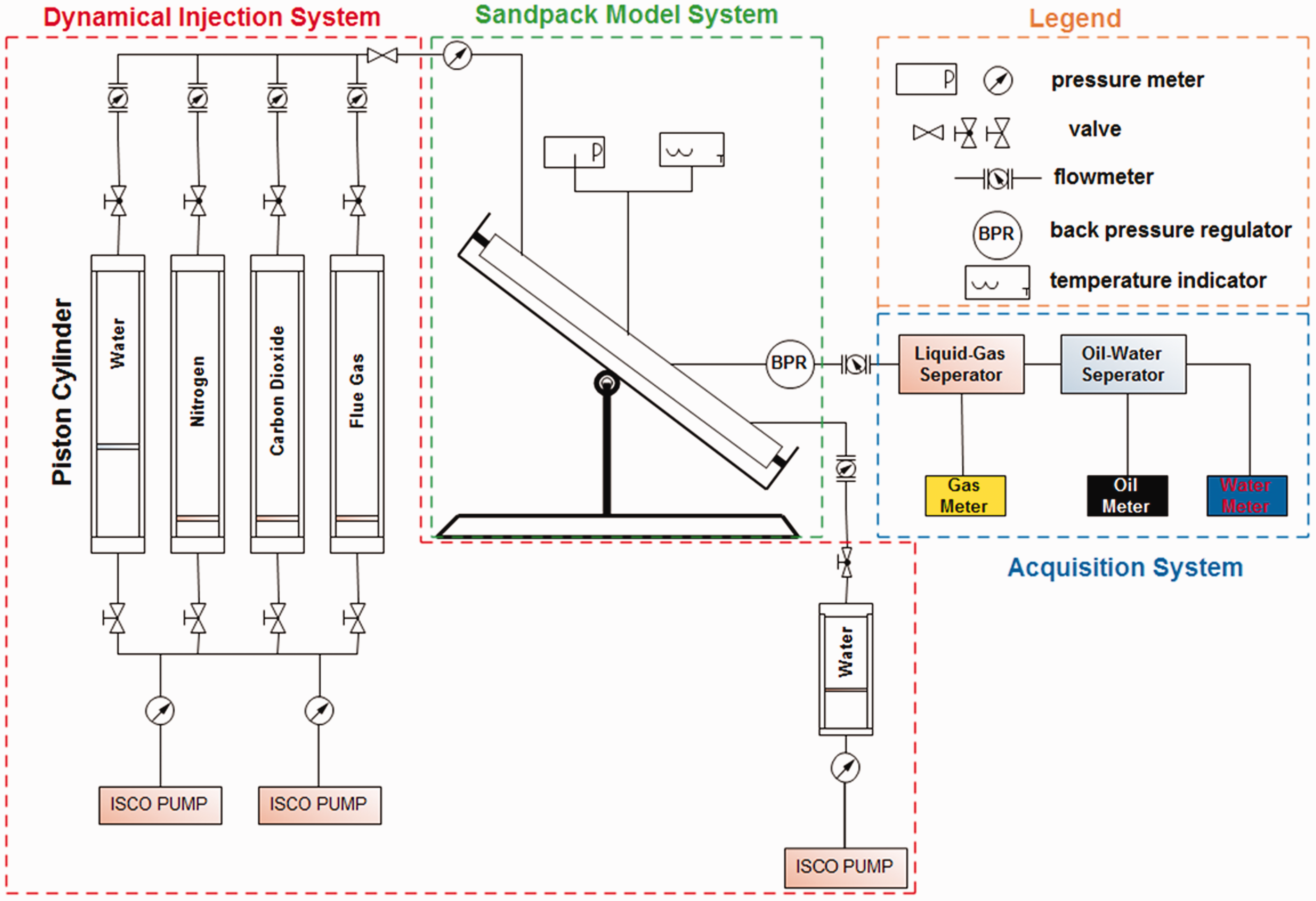
Schematic experimental apparatus for the sandpack flooding model.
Experimental procedure
Main experiment steps for the unidirectional displacement
The Sandpack model is prepared with specified permeability and porosity ranges. The detailed measurement steps are as follows: The water injection well at the bottom of the sandpack model is closed. Then it is saturated with water after evacuation for 4 h. The pore volume is measured (2212–2588 mD) and the permeability (36.18%–38.56%) is calculated at atmospheric pressure and room temperature (25°C), respectively. After the temperature of the sandpack model reaches 90°C constant in the incubator and the pressure meter in the model shows 5 MPa, it is saturated with simulated oil at the rate of 0.1 mL/min until the produced fluid composition has no water. Then the irreducible water saturation (Swi=0.186) and the initial oil saturation (So=0.814) are calculated. For water flooding, the ISCO plunger pump injects water from top to down into the sandpack model at a constant injection rate of 2 mL/min until the effluent composition has no oil. The effluent rate of gas, water and oil is measured, respectively. For gas flooding, the experimental steps from (1) to (3) need to be repeated. But the ISCO plunger pump injects CO2, N2 and flue gas into the sandpack model instead of water until the effluent composition has no oil.
Main experiment steps for the bidirectional displacement
Repeat the steps of (1) and (2) in the experimental steps for the unidirectional displacement. For water flooding, the water injection well at the bottom of the sandpack model is open. The ISCO plunger pump injects water from top to down and from down to top synchronously into the sandpack model at a constant injection rate of 1 mL/min, until the effluent composition has no oil. The produced gas, water and oil are measured, respectively. For gas flooding, the ISCO plunger pump injects CO2, N2 and flue gas into the sandpack model at a constant injection rate of 1 mL/min, and simultaneously water is pumped into the sandpack model from down to top at a constant injection rate of 1 mL/min until the effluent composition has no oil. The produced gas, water and oil are measured, respectively. For the ratio of gas and water injection velocity, repeating the steps of (1) and (3). Based on the constant total injection rate, the saturated oil is displaced by the different velocity ratio α, which is defined as the rate of gas injection velocity over water injection velocity, namely 1:2, 2:1, 1:3 and 3:1. The produced gas, water and oil are measured, respectively.
Numerical simulation process
The numerical simulation process by using a commercial numerical simulation software Eclipse 100 (IBM Corporation) has two functions, the first one is to help establish a theoretical geological simulation model in order to determine the suitable reservoirs for the bidirectional displacement to improve oil recovery. Based on the geological information of the X48 reservoir in Dongxin production area, the second function is to help validate the accuracy of the experiments we proposed in this paper by comparing the oil recovery and the oil production rate.
Screening criteria for reservoirs
The theoretical geological simulation model of the bidirectional displacement is established by using commercial numerical simulation software. The injection and production wells in the model are shown in Figure 4. It is worth noting that all injection and production volume are defined at the reservoir conditions. The ratio between injection and production volume is 1:1, and the ratio of gas injection well (I1) and water injection (I2) is 1:1. The oil saturation distribution after 100-days bidirectional displacement is shown in Figure 4(a) and then the pressure distribution of the black dotted line in Figure 4(a) is shown in Figure 4(b). The factors of the bidirectional displacement include geological factors, fluids factors and developmental factors. The detailed categories about the influential factors are shown in Figure 5. The sensitive evaluation (
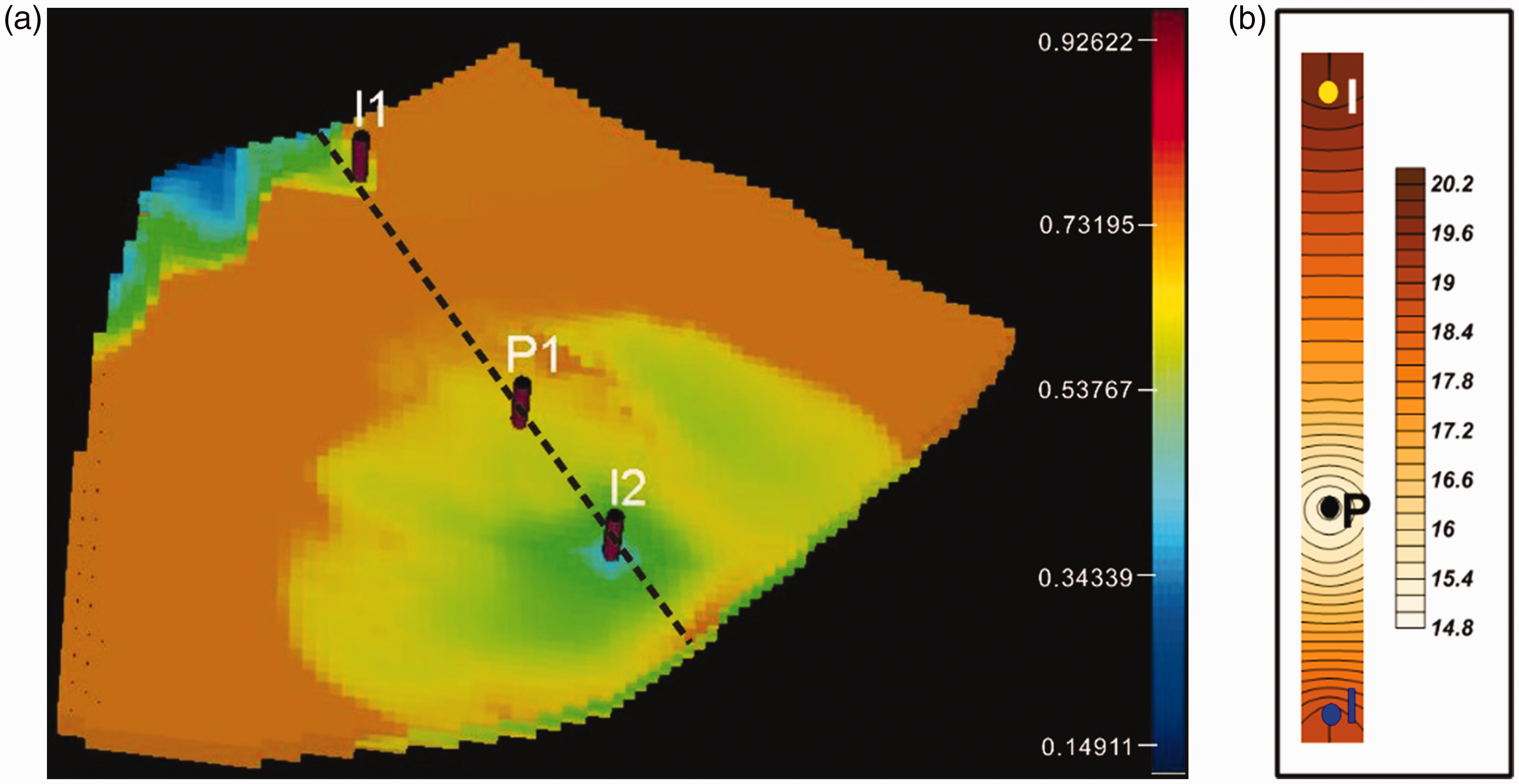
Saturation and pressure distribution in the ideal geological model. (a) Saturation distribution after 100-days bidirectional displacement process. (b) Pressure distribution of the black dotted line in (4a).
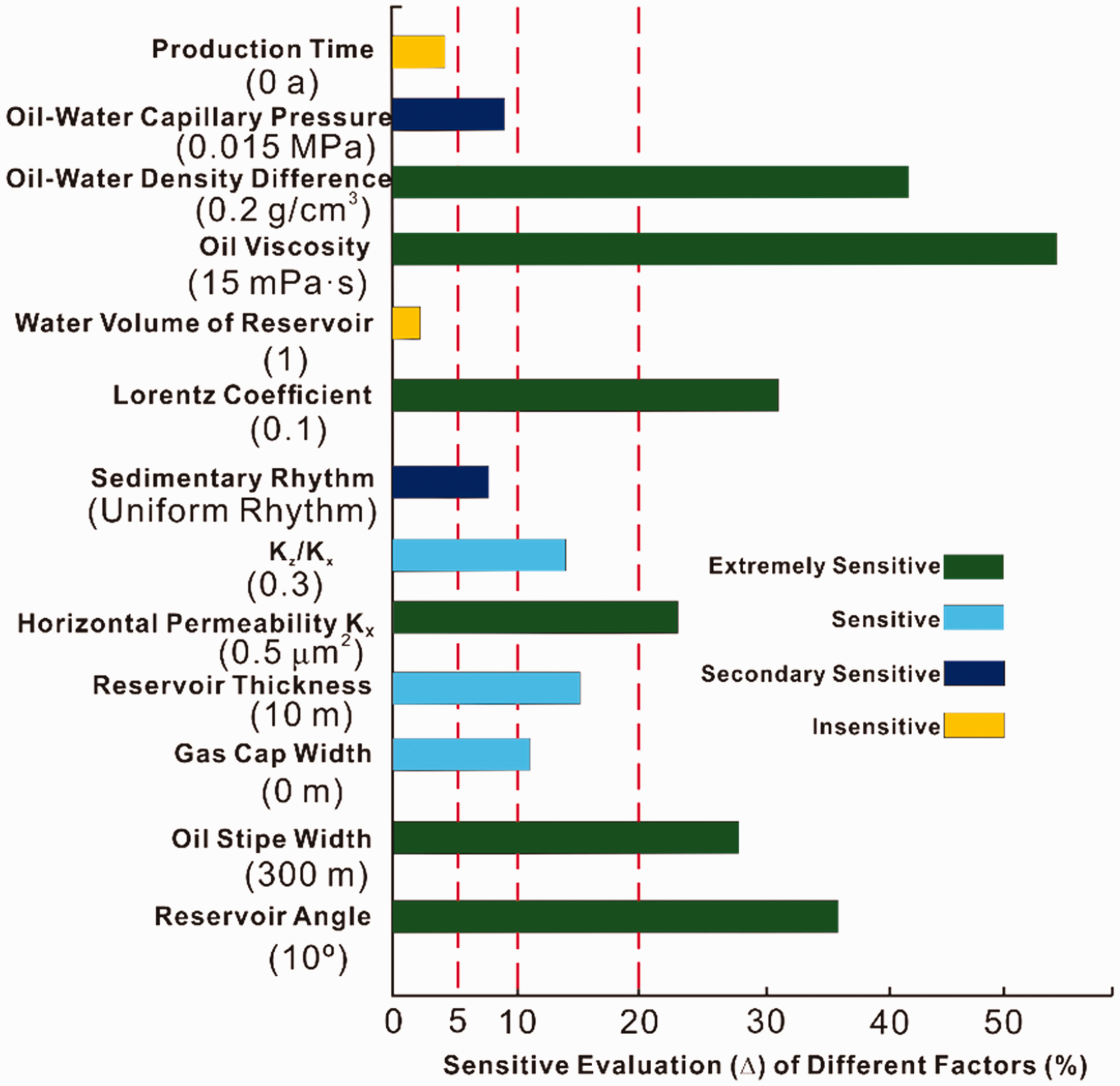
Sensitivity evaluation (Δ) of different influential factors on oil recovery.
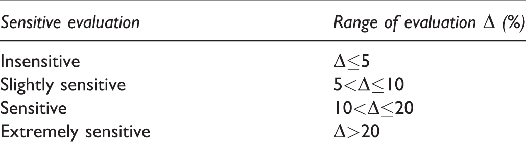
The categories of sensitive evaluation (Δ).
The tornado chart in Figure 5 reveals explicitly that extremely sensitive factors include stratum oil viscosity, density difference of water and oil, dip angle of reservoir, oil stripe width, average permeability and vertical heterogeneity. Other factors are comparatively insensitive to the reservoirs by using the bidirectional displacement EOR method.
Based on extremely sensitive factors, the incremental oil recovery factor by the bidirectional displacement method is compared with the percentage only by water injection. The total production volume from one production well (P1) in Figure 4(a) during the bidirectional displacement process is equal to that of two production wells by changing the gas injection well (I1) into a production well. The results indicate that the reservoirs with less than 100 m of oil stripe width, less than 8° of stratum dip angle, less than 150 × 10−3μm2 of average permeability, more than 75 mPa·s of stratum oil viscosity, less than 50 g·cm−3 of the oil–gas density difference, and less than 0.1 of Lorentz coefficient are unsuitable to carry out the bidirectional displacement method for EOR.
Simulation of the X48 reservoir
Dongxin production area is located in the Eastern part of the central uplift zone between Dongying depression and Jiyang depression, as shown in Figure 6. It is a typical representative of the faulted and depressed hydrocarbon basins in China. The complicated fault block reservoir has entered into high water cut period of about 90.2% and 36.6% of oil recovery rate. The remaining oil area is concentrated in the updip position of the reservoirs and the water area is distributed in the downdip position.
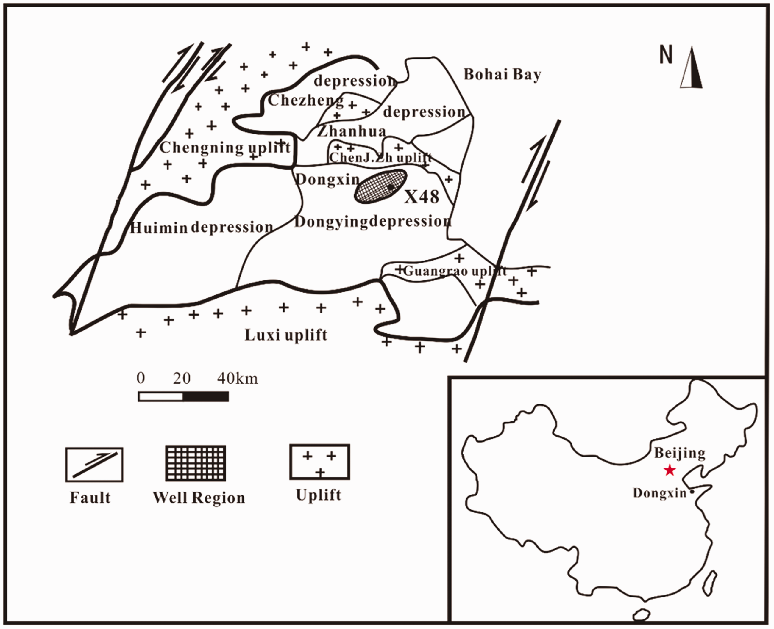
The geological structure map and the focus region of the Bohai Bay basin.
The main research area is the X48 reservoir, which is an inclined reverse ridge block reservoir, as shown in Figure 6. The average width of the reservoir is 600–800 m and the height of the oil stripe is 90–125 m. The water cut is more than 90% and the oil recovery factor is less than 40%. The remaining recoverable reserve is 3.9 × 10⁴t in this reservoir after water injection development for many years. The inclined angle of the X48 reservoir is 9°. Based on the statistical analysis of core samples, the average porosity is 22.3% and the average permeability is 168.25 × 10⁻³ μm2. The average oil viscosity is 9 mPa·s at 90°C and the average oil density on surface condition is 0.85 g·cm−3. The historical development system of Dongxin X48 reservoir is shown in Table 2.
Historical development system in Dongxin X48 reservoir.
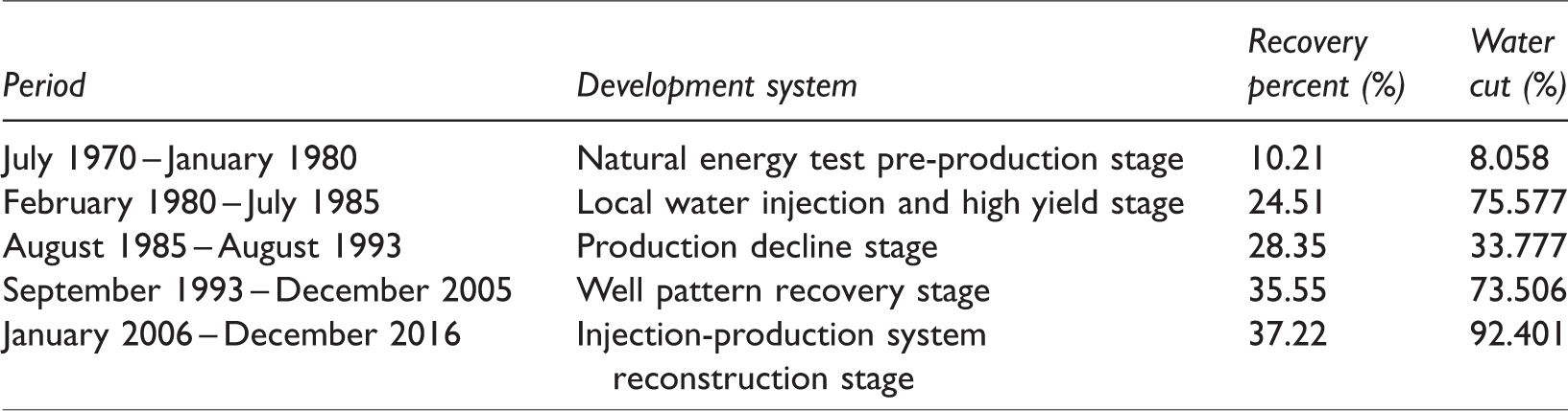
A method of bidirectional displacement with artificial gas cap and edge water has been a very novel and challenging area of study. The success of the synergistic process of gas and water flooding does not only depend on the stratum structure, but also strongly depends on the operating conditions (Liu et al., 2009). It is vital to find out the proper operating conditions for the bidirectional displacement to make the highest oil recovery at the lowest costs under Dongxin production area, Shengli Oilfield. A three-dimensional numerical simulation model is established based on fine reservoir description of the research area. The sketchy plane plot of the research area is shown in Figure 7. Only three wells are considered to study the bidirectional displacement method in the numerical simulation process, namely X4841, X48CXN9 injection wells and X4838 production well. Based on the historical matching process and comparison with oil production data of water flooding for the given original injection well (X48CXN9), the numerical simulation processes of unidirectional or bidirectional oil displacement and the optimal rate of the injected gas to water are evaluated in this section.
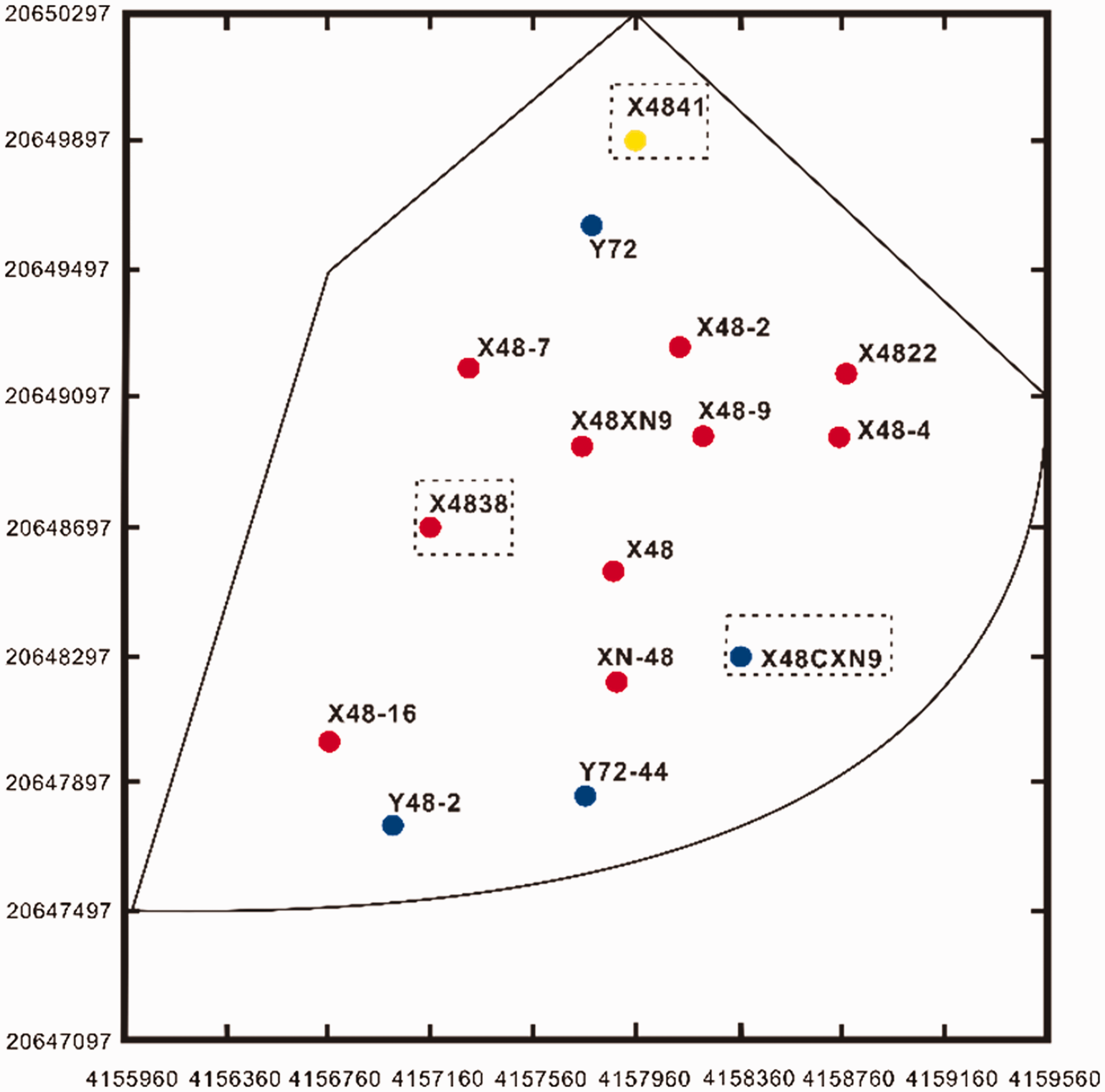
Sketchy plane graph of the research area.
Results and discussion
Experimental results
Two experimental works have been conducted to state the benefits of bidirectional displacement with artificial nitrogen gas cap and edge water, as shown through Figures 8 to 11. An experimental work has been tested for the optimum rate (α) of nitrogen injection velocity over water injection velocity for oil recovery, as shown in Figure 12.
Experimental evaluation for the different unidirectional displacement
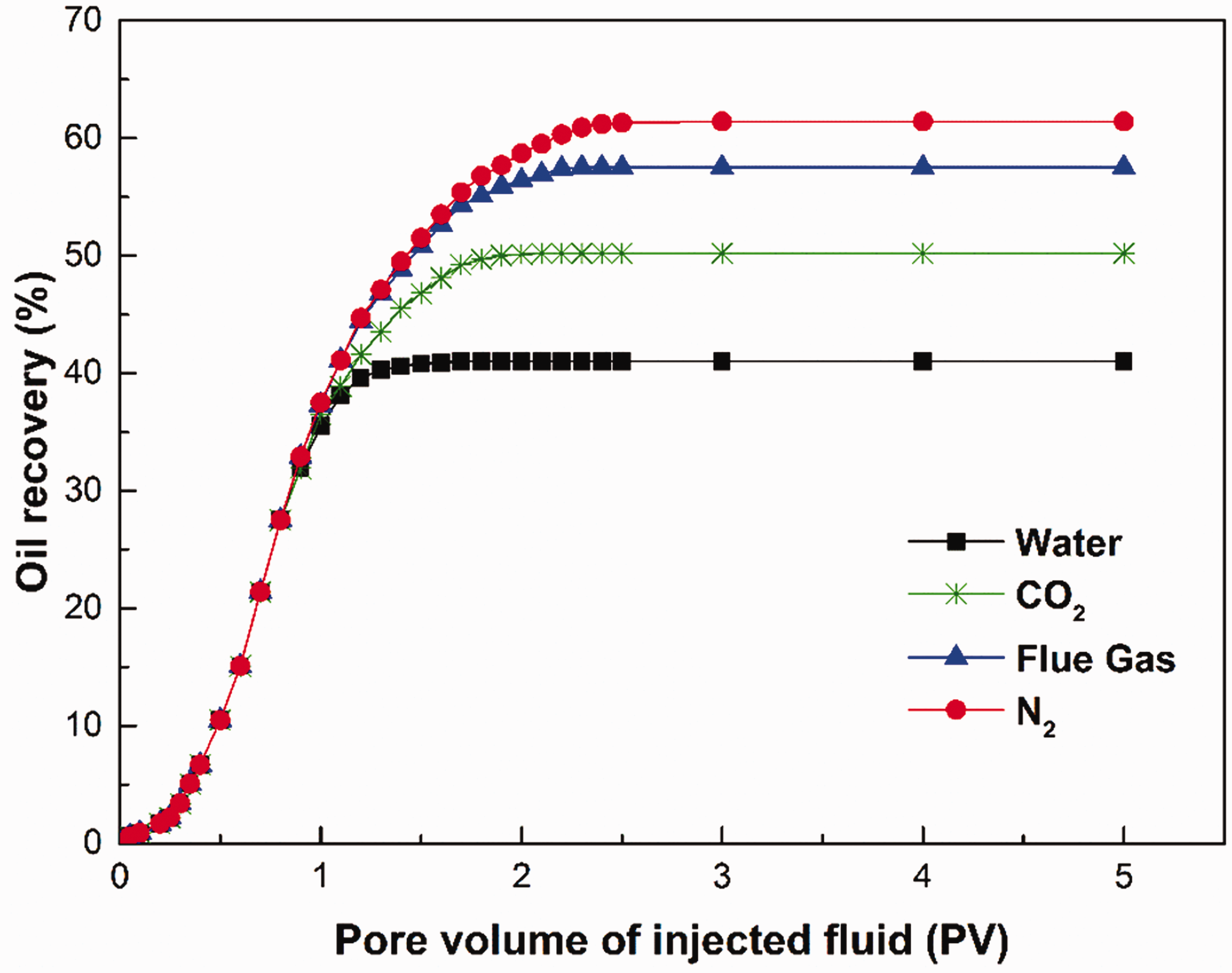
Figure 8 shows the oil recovery factor as a function of pore volume of different injection fluids. As we expect, the total oil recovery increases and then tends to be stable with increasing pore volume of injected fluids. The oil recovery by nitrogen flooding, flue gas flooding and carbon dioxide flooding is higher than that of water flooding by 20.5%. The oil recovery by nitrogen flooding has more recovery advantage up to 42% than that of carbon dioxide flooding with 33.7%. This is probably due to the fact that there is density difference in immiscible flooding process. That is to say, the gas channeling easily forms by carbon dioxide flooding because of carbon dioxide density being higher than nitrogen density or flue gas density in the sandpack model. When the pore volume of the injected fluid is less than 1 PV, the pace of oil recovery increased faster by water flooding than the other three flooding methods (CO2, flue gas and N2). The water injection is apt to flow along large throat pore and enter into small pore space difficultly because of high gravity results. The higher the density of fluids injection, the lower the viscosity of gas injection, and the easier the injected gas flows along large throat pore, the easier the gas channeling happens. Consequently, a gas cap is difficult to be formed in the updip position of the inclined reservoir so that the sweep efficiency decreases in EOR process. In addition, nitrogen gas has stronger expansion capacity because of higher compression factor than the other gases (CO2 and flue gas).
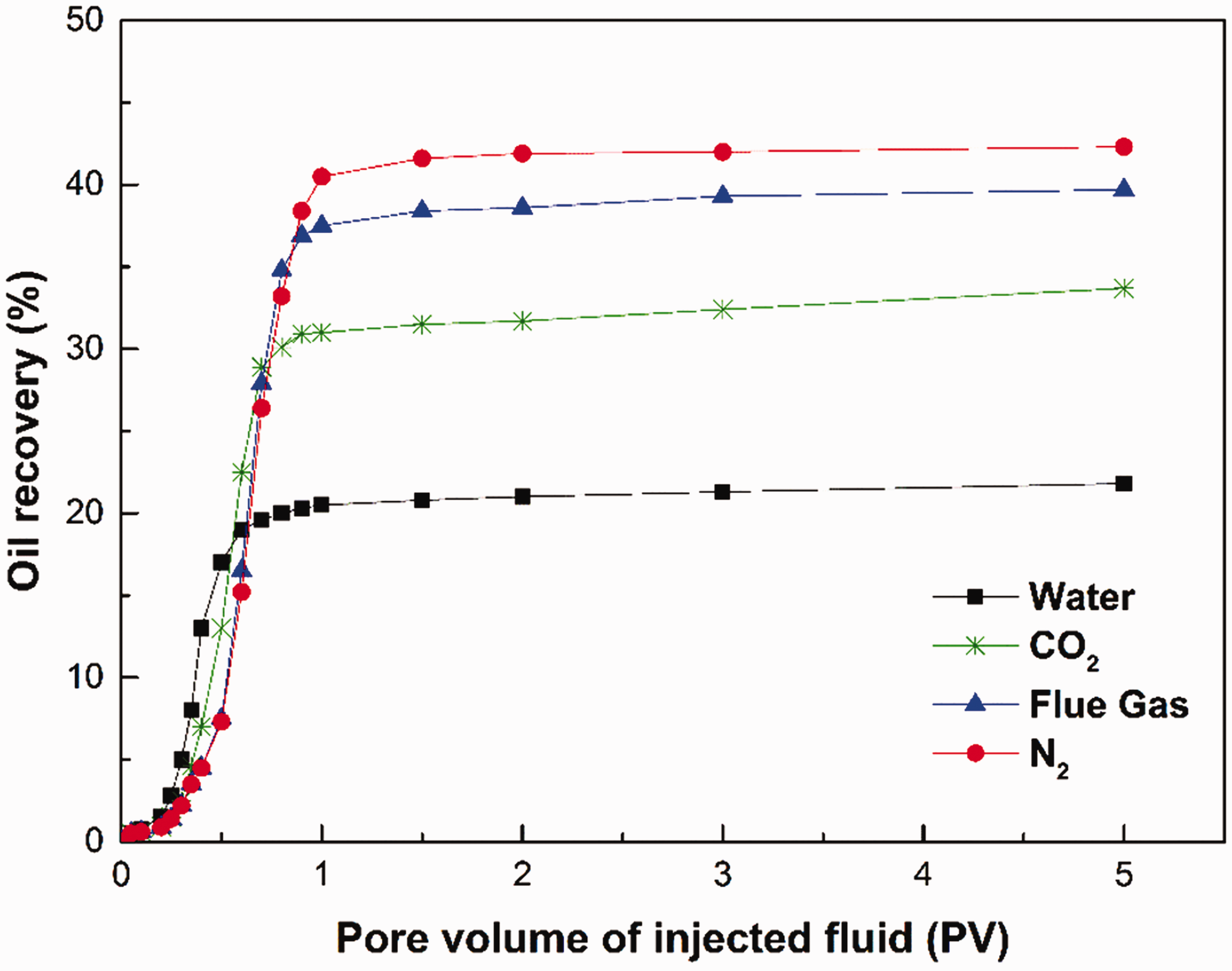
Relationship between oil recovery and pore volume of different injected fluids.
Figure 9 depicts the gas production rate of the effluent composition under four different displacement methods. Obviously, there is scarcely any gas production by water flooding, and 0.85 PV of carbon dioxide injection or 0.99 PV of flue gas injection or 1.08 PV of nitrogen injection reach a constant gas production rate of 98%. This indicates that the pace of gas channeling is different by the three gas flooding methods (CO2, flue gas and N2). The gas channeling phenomenon in the sandpack needs more pore volume of nitrogen gas injection than that of carbon dioxide or flue gas injection.
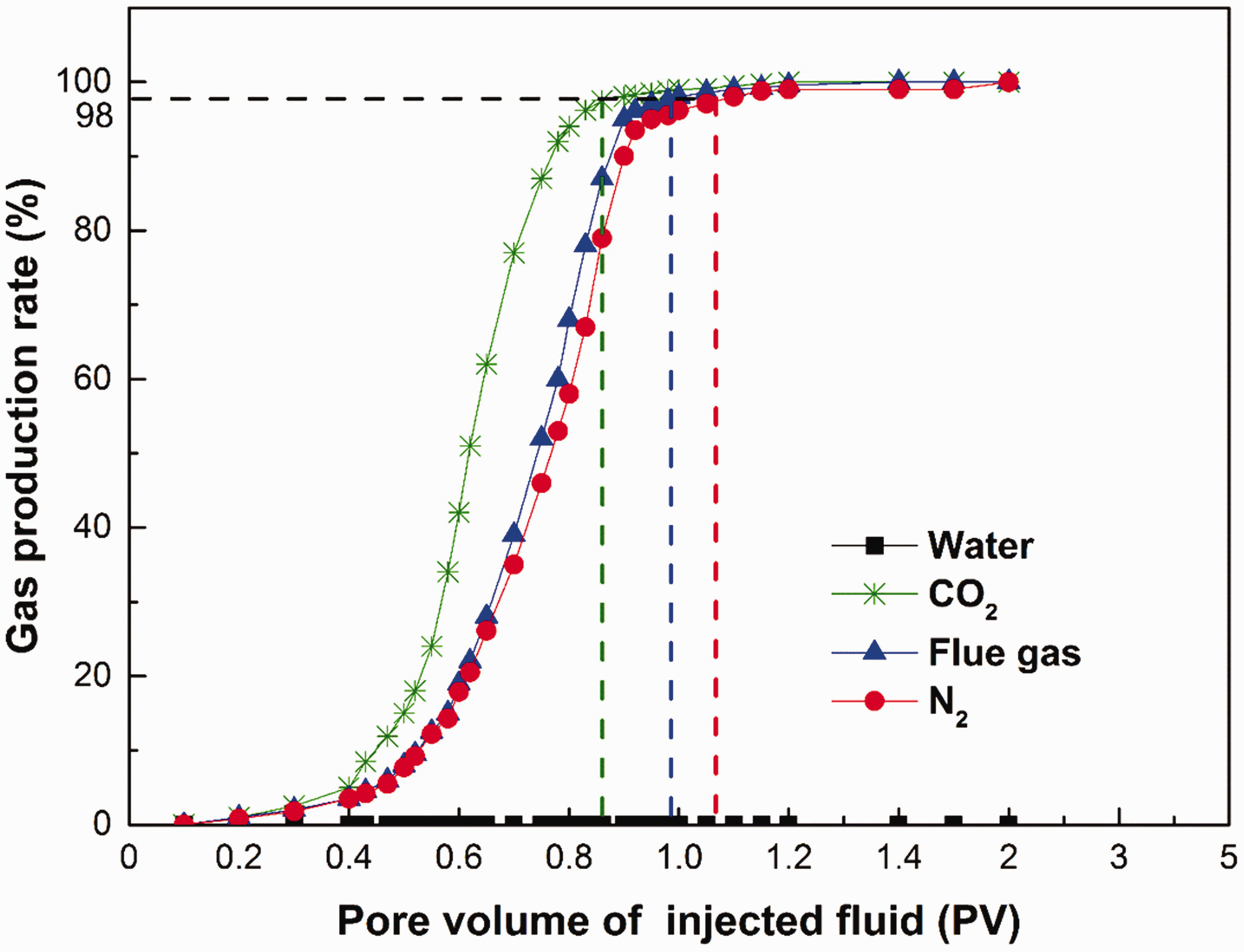
Relationship between gas production rate and pore volume of injected fluids.
From the experimental results for the unidirectional displacement, we draw a conclusion that nitrogen flooding can implement the stratum energy by the volume swelling to improve oil recovery more effectively than by water flooding, carbon dioxide flooding or flue gas flooding. The lower the density of injected gas, the easier the formation of the gas cap (gravity segregation). During the gas displacement process, the lower the viscosity of the injected gas, the easier the gas channeling will occur, resulting in the lower sweep efficiency.
Experimental evaluation for the bidirectional displacement
During the bidirectional displacement process with gas cap and edge water, the oil recovery factor by immiscible fluids injection, like water, carbon dioxide, flue gas and nitrogen gas, is calculated as shown in Figure 10. The results show the oil recovery obtained by the bidirectional displacement of nitrogen flooding at the updip position of the inclined sandpack model and water flooding at the downdip position of the inclined sandpack model (N-W flooding) with 64.6%, as shown in Figure 2. The oil recovery of N-W flooding is higher than 41.3% of water flooding at the updip position and edge water flooding at the downdip position (W-W flooding), 52.1% of carbon dioxide flooding at the updip position and water flooding at the downdip position (C-W flooding), 59.8% of flue gas flooding at the updip position and water flooding at the downdip position (F-W flooding), respectively. This is due to the synergistic effect of the injected fluids shown in Figure 1(b), which is beneficial to increase stratum energy for IOR. In addition, when the pore volume of the injected fluids is less than 1.3 PV, the pace of the oil recovery increases similarly because of main energy from edge water injection at the downdip position of sandpack. Whereafter, the incremental pace of the oil recovery is different because of main energy from the different gases injection at the updip position of the sandpack model. However, the ultimate oil recovery factors tend to be invariable.
Relationship between oil recovery and pore volume of different injected fluid.
Figure 11 shows the relationship between gas and water production rates with the pore volume of the different injected fluids under a constant effluent production rate. As expected, by the bidirectional displacement of W-W flooding, water production rate with 1.3 PV water injection reaches 100% but gas production rate was about 0% continuously. In addition, reaching 50% of water production rate and 50% of gas production rate by C-W flooding, F-W flooding or N-W flooding needs 1.8 PV of the total injected carbon dioxide and water, 2.2 PV of the total injected flue gas and water, 2.4 PV of the total injected nitrogen and water, respectively. The results illustrate that water flooding retards the gas migration to the production well and conversely gas flooding mitigates water flow towards the outlet of the sandpack model. Moreover, the density difference and gas viscosity play an important role on enhanced sweep efficiency.
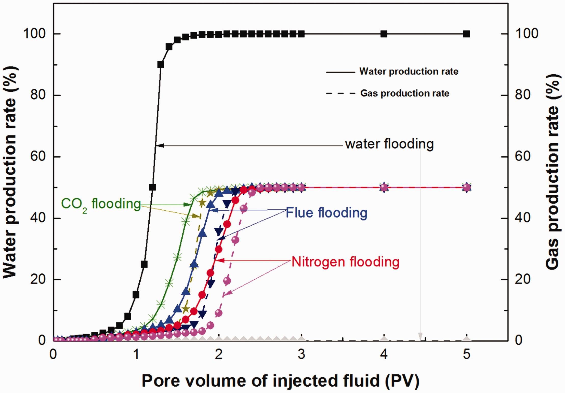
Gas and water production rates with pore volume of injected fluid.
Experimental evaluation of optimum rate (α) for bidirectional displacement
The effect of different velocity proportion (α) of nitrogen and water injection on oil recovery is shown in Figure 12. Based on the constant production rate in the outlet of the sandpack model, when the injected nitrogen velocity is 1 mL/min and the injected water velocity is 1 mL/min in the sandpack experiment, the oil recovery has the highest percentage at 64.6%. Increasing the injected nitrogen velocity or decreasing the injected water velocity, the ultimate oil recovery dropped to 40.4% and 33.2%, respectively. On the contrast, with the increment of the injected water velocity or the decrease of the injected nitrogen velocity, the ultimate oil recovery dropped to 41.6% at α = 1:2 and 37.4% at α = 1:3, respectively. The large amount of injected water or gas is apt to decrease the oil recovery. The satisfactory results are attributed to the mutual interaction between water and nitrogen injection.
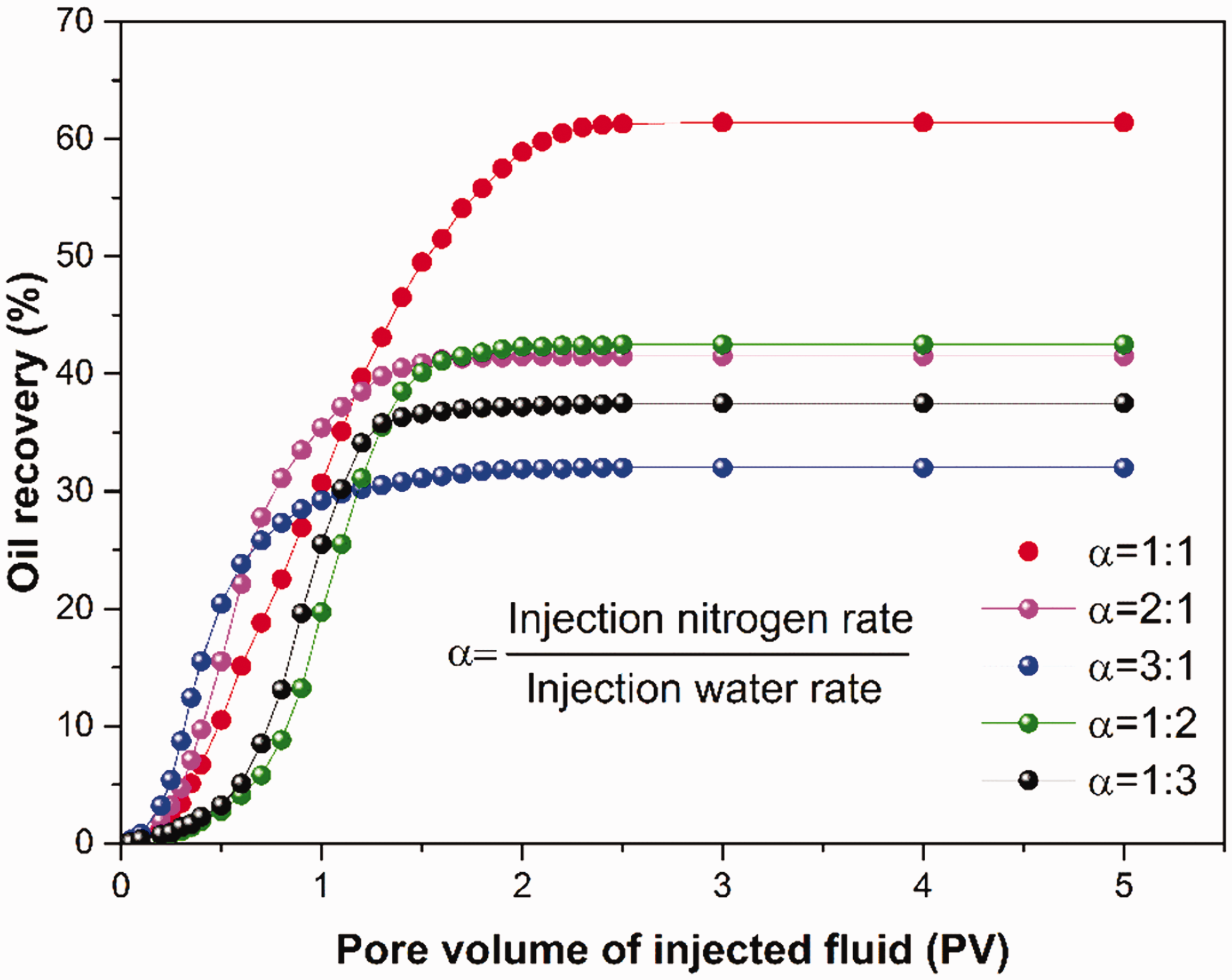
Oil recovery under different injected velocity multiple (α) of nitrogen and water with pore volume.
The obtained results from the unidirectional or the bidirectional displacement experiments and the optimum rate (α) for the bidirectional displacement experiment indicate that, the main mechanism for the high oil recovery is due to the increment of the sweep efficiency caused by density difference, viscosity and mutual interaction, inhibiting the water invasion and the gas channeling. There is a need to ensure a suitable velocity proportion (α) of nitrogen injection from top to down and water injection from down to top in the sandpack model to reduce undesired behaviors, which appears to be quick water breakthrough and gas channeling.
Numerical simulation results
Numerical simulation evaluation for the unidirectional displacement
Figure 13 shows the changes of the oil production rate and the oil recovery factor with production time under different injected fluids. The historical matching curve of oil production rate from 1970 to 2016 is seen at the top of Figure 13. The black solid line and the dotted line at the bottom of Figure 13 show the oil production rate and the oil recovery factor correspondingly obtained by water injection in the X48CXN9 injection well, when the X4841 injection well is closed and the X4838 production well is open, as shown in Figure 7. The four different solid lines and correspondent dotted lines (red, blue, green and pink) show the oil production rate and the oil recovery obtained from the X4838 production well by injecting different fluids displacement into the X4841 injection well in the unidirectional process, when the X48CXN9 injection well is closed. The obtained results are higher than the production performance (black line) of original water flooding only from the X48CXN9 injection well. The oil production rate and the oil recovery of different gas flooding (red, blue and green lines) are higher than that of water flooding in the X4841 injection well (pink). Markedly, the oil production rate and the oil recovery of nitrogen flooding (red) were the highest. The oil production rate (solid lines) of nitrogen flooding (red), carbon dioxide flooding (blue), flue gas flooding (green) and water flooding (pink) from the X4841 injection well rises sharply to 9.4 m3/day, 9.1 m3/day, 8.65 m3/day and 6 m3/day, respectively and then stably declines to 4.92 m3/day, 4.62 m3/day, 4.21 m3/day and 2.73 m3/day, respectively. The results indicate that the rising oil production rate is due to the injected gas swelling or the sufficient stratum energy, and the oil production rate stably reduces because of gas channeling or water fingering phenomenon.
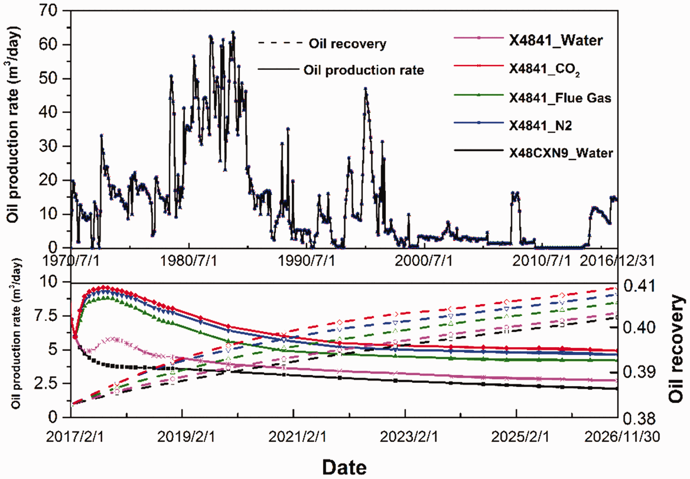
Oil production rate and oil recovery with dates under different injected fluids.
Numerical simulation evaluation for the bidirectional displacement
The bidirectional displacement process is defined that the fluids are injected into the X4841 injection well at the updip position of the reservoir, the edge water is injected into the X48CXN9 injection well at the downdip position of the reservoir, and the oil is produced from the X4838 production well, as shown in Figure 7. The total injected fluids volume in the bidirectional displacement process is equal to the injected volume of water from the X48CXN9 injection well in unidirectional displacement process. The relationship of the oil production rate and the oil recovery with production time under different displacement methods in the bidirectional displacement process is illustrated in Figure 14. However, the ultimate oil production rate and the oil recovery in the bidirectional displacement process shown in Figure 14 are higher than the results of unidirectional displacement process shown in Figure 13. In the bidirectional displacement process, the production performances of gas injection from X4841 injection well (red, blue and green lines) are higher than that of water injection from the X4841 injection well (pink line). The bidirectional displacement method of nitrogen gas injection from the X4841 injection well and water injection from the X48CXN9 injection well simultaneously (red line) has higher recovery efficiency with 8.5 m3/day of the ultimate oil production rate (red solid line) and 0.112 of the ultimate incremental oil recovery (red dotted line) than the production results of the original unidirectional water flooding from the X48CXN9 injection well (black solid and dotted lines). The results of the oil recovery in Figure 14 are consistent with the experimental results in Figure 10. The bidirectional displacement process mitigates the pace of gas channeling or water invasion, owing to the density difference, the viscosity and the synergistic effect of the injected fluids.
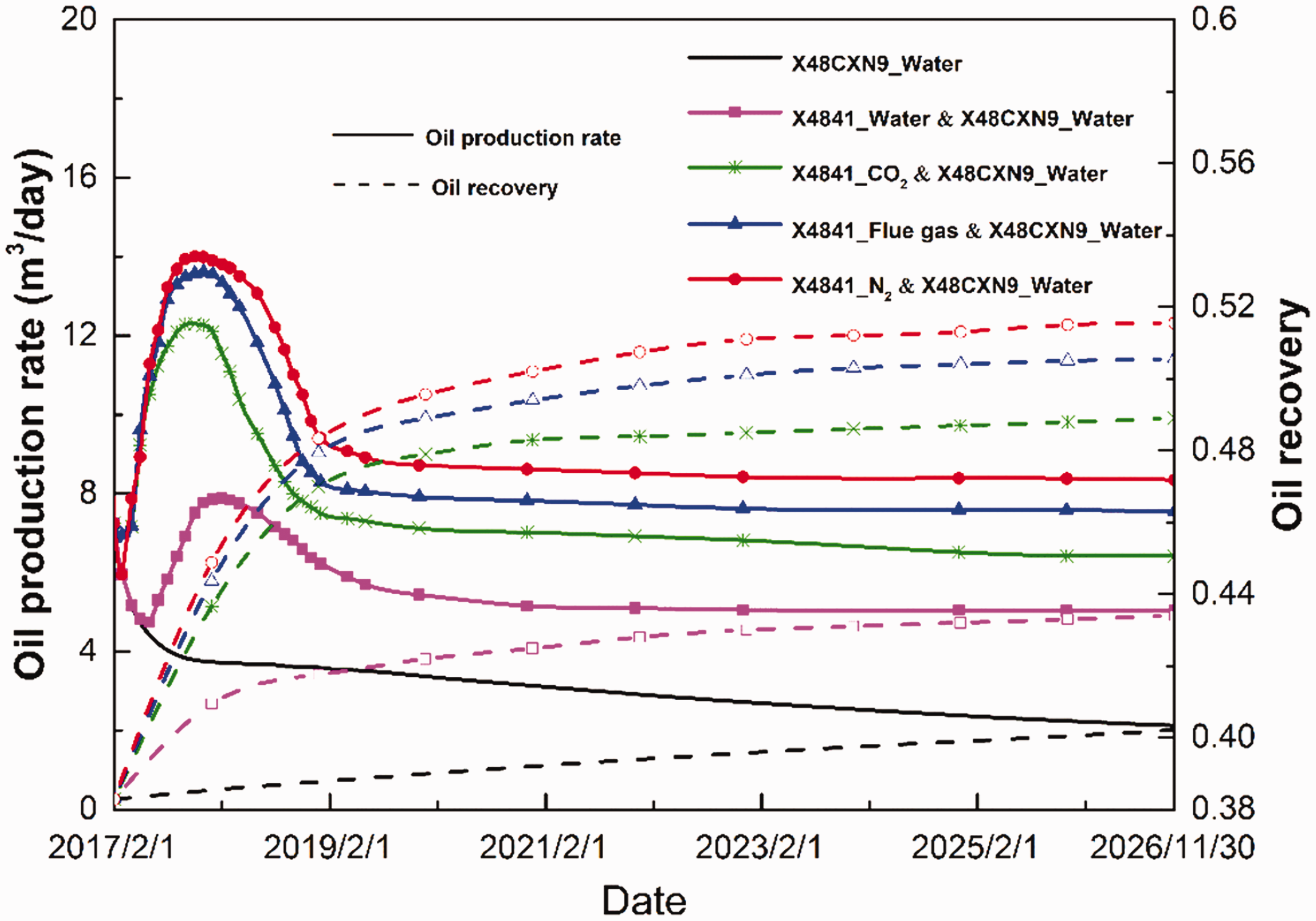
Oil production rate and oil recovery with dates under different displacement methods.
Optimizing rate (α) of injected nitrogen gas to injected water
Figure 15 shows the cumulative oil with production time under different injection ratio (α) of nitrogen injection rate from the X4841 injection well to water injection rate from the X48CXN9 injection well. From 1 February 2017 to 30 November 2026, when the ratio of nitrogen gas injection to water injection is 1:1 (red line), the ultimate cumulative oil with 25160.8 m3 is much higher than the production results of other ratios of nitrogen injection to water injection, and the original water injection only with 11489.27 m3. The more the nitrogen gas injection volume per day, the quicker the incremental pace of the cumulative oil at the early stage, but the rising pace slows down quickly at the latter stage. This is because the nitrogen gas injection volume timely keeps the reservoir’s energy, but too much gas leads to serious gas channeling. Similarly, too much water may initiate water channeling or water invasion. The results in Figure 15 are consistent with the experimental results in Figure 12.
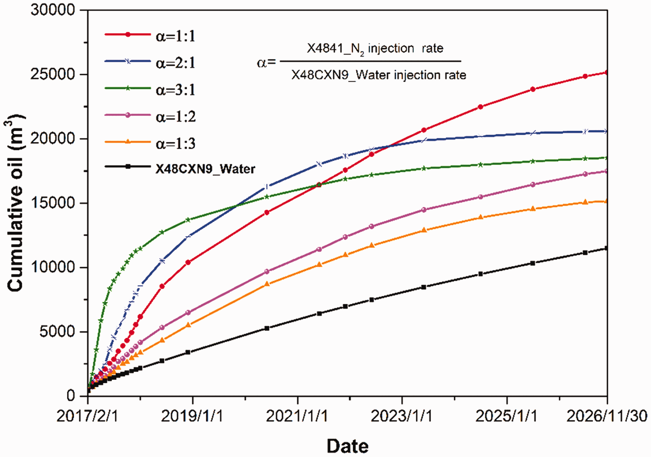
Cumulative oil SC with dates under different injection ratio α.
Conclusions
Based on experiments and numerical simulation, the main conclusions drawn from this study are as follows:
Three-phase gravity index Nr≤1 represents the stable oil displacement process; Nr>1, gas channeling and water fingering are formed easily. The sensitive evaluation ranges (Δ) were defined as the difference between the maximum oil recovery and minimum oil recovery percentage, which was used to evaluate the effects of different factors on reservoirs by using the bidirectional displacement EOR method From the experimental results, the bidirectional displacement by nitrogen-water flooding (N-W flooding) has more recovery advantages up to 64.6% than 42% by the unidirectional nitrogen injection flooding. The nitrogen-water flooding (N-W flooding) process has more residence to displace oil in the sandpack model than the other displacement ways. The optimal rate of nitrogen gas to water injection is 1:1. The numerical simulation results of the study area were perfectly consistent with the experimental results by using the bidirectional displacement. Nitrogen gas injection from the X4841 injection well and water injection from the X48CXN9 injection well cooperatively have better recovery efficiency with 8.5 m3/day of ultimate oil production rate. The method of bidirectional displacement with artificial nitrogen gas cap and edge water is feasible for the X48 inclined reservoir in Dongxin production area, Shengli Oilfield. This method is able to improve the ultimate oil recovery factor by 11.2%.
Footnotes
Authors' note
Eric Thompson Brantson is now affiliated with Department of Petroleum Engineering, Faculty of Mineral Resources Technology, University of Mines and Technology, Tarkwa, Ghan.
Acknowledgements
The authors would like to thank the editors and anonymous referees for their valuable comments and suggestions.
Declaration of conflicting Interests
The author(s) declared no potential conflicts of interest with respect to the research, authorship, and/or publication of this article.
Funding
The author(s) disclosed receipt of the following financial support for the research, authorship, and/or publication of this article: The research was supported by the Fundamental Research Funds for National Science and Technology Major Projects (2016ZX05011-002 and 2017ZX05009-005).