
Abstract
A measurement study was conducted for the effective drainage radius of borehole along coal seam #9 of the Kaiyuan Coal Mine using the gas pressure method and gas flow method. The measurement results show that the effective drainage radius of borehole along coal seam #9 was 0.75 m, 27 days after drainage, and 1.5 m, 92 days after drainage. Experimental schemes were designed for the entire evolution of the stress in the coal mass around the borehole, and an experimental study on methane seepage in the coal mass around borehole was conducted. Fitting functions for the permeability of the coal sample and its vertical stress were obtained by fitting the experimental data. Based on the vertical stress–permeability functional relationship of coal masses around borehole, a numerical calculation model for methane seepage from coal masses around borehole was established, and the influences of drainage time, initial gas pressure, borehole diameter, and drainage negative pressure on the effective drainage radius of borehole were investigated. The numerical simulation results show that with the increase in initial gas pressure and borehole diameter, the effective drainage radius of borehole increases continuously but its increase amplitude decreases constantly. With the increase in drainage negative pressure, the effective drainage radius of borehole increases linearly but the increase amplitude is relatively small. The layout parameters of borehole along coal seam #9 of the Kaiyuan Coal Mine were optimized based on the numerical calculation results, and the reasonable drainage time, reasonable borehole diameter, and reasonable drainage negative pressure are 180 days, 120 mm, and 15 kPa, respectively, for the borehole along coal seam #9.
Keywords
Introduction
Coalbed methane is a source of clean energy, and its calorific capacity per cubic meter can reach 33.5–36.8 MJ, which is equivalent to that of 1.22 kg of standard coal or 1.13 L of standard oil (Jackson and Kershaw, 1996; Qian, 2016). Boreholes along the coal seam are primarily used for pre-drainage of gas from the coal seam being worked in China at present. The effective drainage radius of borehole is an important parameter in this means, and it has a direct bearing on the determination of pre-drainage borehole spacing. If the gas drainage borehole spacing is too large, there will be drainage blind zones formed between drainage boreholes, bringing extremely large hidden troubles of accident for production in coal mines. If the gas drainage borehole spacing is too small, the gas drainage rate and gas drainage volume may be increased to a certain extent, but this will increase the borehole construction workload, raising the gas drainage cost. Therefore, reasonable borehole spacing should be determined on the basis of accurately knowing the effective drainage radius of the borehole along the coal seam.
Over the past decades, scholars from various countries have studied the effective drainage radius of borehole in the process of natural gas exploitation. Valliappan and Zhang (1996) proposed a mathematical model in which the effect of diffusion of adsorbed methane gas from the solid matrix to the voids was taken into account. Li et al. (2017) established a mathematical model of gas flow in different types of wells on the basis of seepage theory. Xia et al. (2016) established a model for slotting the radius of high pressure water jet slotting based on the theory of round turbulent jet and Loland damage model. Y Zhang et al. (2012) investigated the determination of the original coal seam gas pressure and content of the coal drainage radius after the hydraulic reaming. Gao et al. (2013) found that the unstable productivity analysis method is applicable in the study of gas well drainage radius. M Hossain et al. (2007) examined the effects of criterion values on the estimated values of the radius of drainage. G Heron (2009) studied the variation regularity in gas pressure and drainage radius under different conditions by using the solid–gas coupled RFPA2D-Gas software. Rosales and Joers (1982) presented a method for determining radius of drainage from data obtained during pressure buildup tests.
The methods currently used for determining the effective drainage radius of the borehole along the coal seam mainly include drilling test method and computer simulation method. China has achieved more research results in this study area. Out of drilling test methods, the gas pressure method and gas flow method are the two common methods for measuring drainage radius. In the gas pressure method, pressure-measuring boreholes are laid at different spacings around a drainage borehole, and the effective drainage radius of drainage borehole is determined by investigating the change in gas pressure in pressure-measuring boreholes, based on the effective drainage radius determining criterion that the gas pressure declines to 51% of the initial gas pressure (Chang, 2012; Li et al., 2016; Li and Liu, 2014; Liang et al., 2013). In the gas flow method, the gas drainage volume from a drainage borehole is measured on the site, the distribution law of gas drainage rates in the coal masses around the drainage borehole is obtained through theoretical calculation, and then the target drainage rate is obtained based on the specific gas emission rate from mine, thus to determine the drainage radius of drainage borehole at a time point (Du and Luo, 2009; Sun et al., 2014; Wang and Guo, 2013; Wei and Qin, 2013). Nevertheless, the gas pressure method has problems including poor sealing of pressure-measuring borehole and low success rate of sealing. The gas content method is simpler than the gas pressure method in operation, but the results are not reliable and cross validation is needed. In the aspect of computer simulation, scholars from China and other countries have established mathematical models to describe the flow laws of gas in the coal seam around the borehole and conducted calculation with CFD software, to obtain the effective drainage radius of the borehole along the coal seam based on the calculation results (Hao et al., 2013; Ji et al., 2013; Li et al., 2014; Lu et al., 2015; Ma et al., 2009; Wang et al., 2012; Wu et al., 2015). Nevertheless, after the construction of the borehole along the coal seam is completed, the stresses in the coal masses around the borehole are redistributed (Figure 1), and a plastic failure occurs in the coal masses relatively close to the borehole, with stress decreasing significantly and permeability increasing evidently. In addition, in the coal masses outside the plastic failure area stress concentration occurs, with permeability decreasing significantly. However, in the currently established models for gas flow around borehole, no influence of the change in stress in coal masses around borehole on the permeability of coal mass has been taken into account, and hence the numerical calculation results differ relatively greatly from the actual situations.
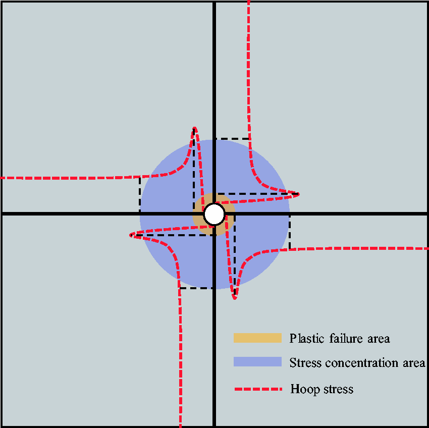
Distribution law of stresses in coal masses around the borehole along the coal seam.
To solve the above problems, this paper proposes a multi-stage segmented borehole-sealing method for pressure-measuring boreholes. The effective drainage radius of the borehole along coal seam #9 of the Kaiyuan Coal Mine was measured on the site by combining the gas pressure method and the gas flow method. In addition, experimental schemes were designed according to the whole process of evolution of the stresses in the coal masses around borehole, and then experimental study on methane seepage in the coal masses around borehole was conducted, to obtain the stress–permeability functional relationship of coal masses around borehole. Based on the stress–permeability functional relationship of coal masses around borehole, a numerical model for methane seepage in coal masses around the borehole was established, and numerical simulation study on the influential factors for effective drainage radius of the borehole along the coal seam was carried out.
On-site measurement of effective drainage radius of the borehole along the coal seam in the Kaiyuan Coal Mine
Overview of working face
The on-site measurement study on the effective drainage radius of the borehole along the coal seam in the Kaiyuan Coal Mine was conducted in the return airway of 9712 working face, and the test area did not undergo gas drainage and was not influenced by the mining at other working faces; hence, the test area met the test requirements for effective drainage radius in the borehole along the coal seam. The ground elevation at the 9712 working face was 1099–1125 m, and the elevation of the working face was 742–758 m. The working face had a strike length of 1360 m and a dip length of 220 m. The coal seam had a thickness of 5.17 m and dip angle range of 1–7°. For this working face, U + L ventilation was used, and the boreholes along the coal seam were used for gas drainage from the coal seam being worked. The boreholes along the coal seam had spacing of 2 m, length of 120 m each, diameter of 120 mm each, and distance from the coal seam floor of 2 m, and the layout of the boreholes along the coal seam is shown in Figure 2. The gas pre-drainage time specified for this working face was 90 days, and the absolute gas emission rate at the working face was less than 20 m3/min; hence, the gas drainage rate from the coal seam being worked at this working face should reach over 30% according to the provision in the Coal Mine Safety Regulation of China.
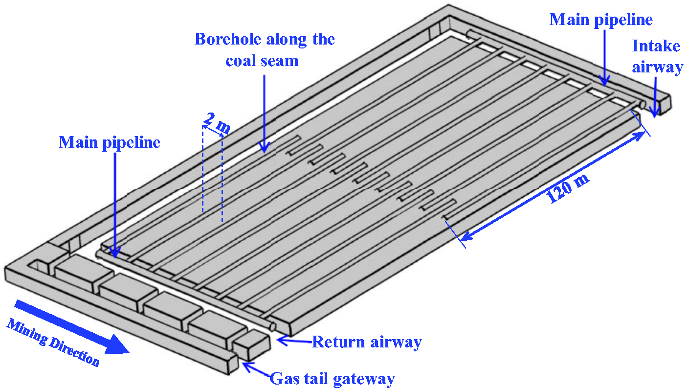
Schematic diagram of layout of the boreholes along the coal seam at 9712 working face in the Kaiyuan Coal Mine.
Scheme for layout of measurement stations
To accurately determine the effective drainage radius of borehole, on-site measurement of drainage radius was conducted using the means of combining borehole pressure method and gas flow method, and the scheme for layout of measurement stations is shown in Figure 3.
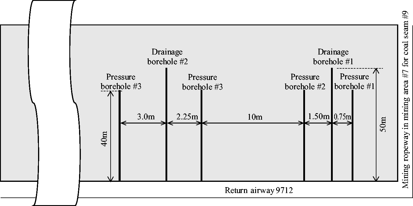
Scheme for layout of test boreholes in return airway of 9712 working face.
Borehole pressure method
There were two groups of test boreholes for gas pressure method laid out in the return airway of the 9712 working face, and those in the middle were drainage boreholes (drainage boreholes #1 and #2) and those on both sides were pressure-measuring boreholes (pressure-measuring boreholes #1, #2, #3, and #4). The length of each drainage borehole was 50 m and that of each pressure-measuring borehole was 40 m, and the diameter was 0.12 m for both drainage borehole and pressure-measuring borehole. The distances between drainage borehole and pressure-measuring boreholes were 0.75, 1.5, 2.25, and 3 m, respectively. The pressure-measuring boreholes were constructed and sealed first, and then the drainage boreholes were constructed and drainage pipelines were connected. After gas drainage from drainage borehole was started, the gas pressure in pressure-measuring borehole was measured on the site. The decrease in gas pressure to 51% of the initial gas pressure was taken as the determining criterion for effective drainage radius of drainage borehole.
Gas flow method
Drainage pipelines were connected for drainage immediately after the construction of the drainage boreholes #1 and #2 was completed. The gas flow rate was monitored and observation was conducted once per day for the drainage boreholes #1 and #2. The gas drainage volume needed for gas drainage rate to reach 30% within a certain range was calculated based on the original gas content in the test area, and finally, the effective drainage radius of drainage borehole was calculated based on the total gas drainage volume.
Borehole-sealing solution for test boreholes
Since the currently used borehole-sealing method for pressure-measuring borehole has problems including poor sealing and low success rate of sealing, this paper gives improvement of the traditional borehole-sealing method of grouting between two sealed ends, and proposes a multi-stage segmented borehole-sealing method. The employed borehole-sealing material was cement mortar, and bag-type borehole-sealing pipes were used. The borehole-sealing process was divided into two stages from inside to outside: 8 m was sealed at the first stage and 24 m was sealed at the second stage. The borehole-sealing solution is shown in Figure 4(a). To prevent coal powder from clogging the pipe opening in the process of pushing pressure-measuring pipe into borehole, screen meshes were punched within 2 m at the tip of pressure-measuring pipe. The drainage borehole sealing length was 8 m, the employed borehole-sealing material was cement mortar, and bag-type borehole-sealing pipes were used. The borehole-sealing solution was shown in Figure 4(b).
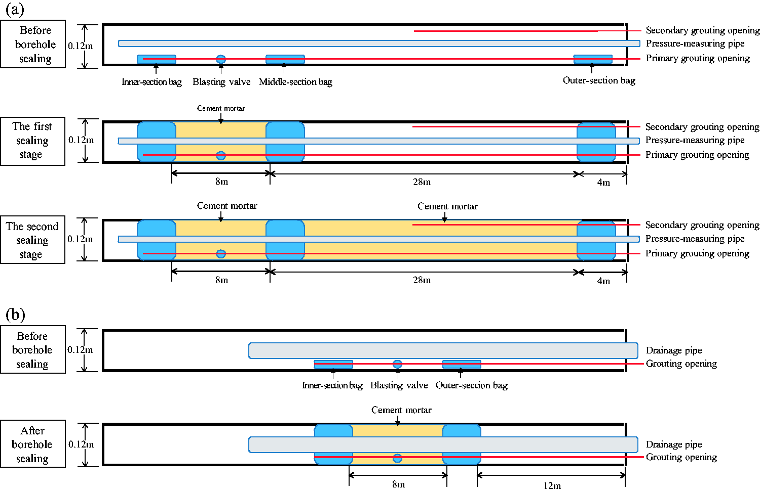
Borehole-sealing solutions for test boreholes: (a) borehole-sealing solution for pressure-measuring borehole and (b) borehole-sealing solution for drainage borehole.
Analysis of measurement results
Measurement results obtained using the gas pressure method
To measure the effective drainage radius of the borehole along coal seam #9, the gas pressures in the pressure-measuring boreholes #1, #2, #3, and #4 were monitored continuously for 180 days, and the curves of the pressure in pressure-measuring borehole and the accumulative drainage volume from corresponding drainage borehole were obtained, as shown in Figure 5. As can be discerned from Figure 5(a), the pressure-measuring borehole #1 was the closest to the drainage borehole #1 (0.75 m); hence, the gas pressure in coal masses at the pressure-measuring borehole #1 declined fastest. Twenty-seven days after drainage, the gas pressure in the pressure-measuring borehole #1 declined from 0.448 MPa to 0.228 MPa, reaching 51% of the initial gas pressure, and the coal masses at the pressure-measuring borehole #1 took the lead to enter the effective drainage radius of the drainage borehole #1. One hundred and eighty days after drainage, the gas pressure in the pressure-measuring borehole #1 declined to 0.138 MPa, and the accumulative gas drainage volume from the drainage borehole #1 was expected to reach 12,042 m3. The distance from the pressure-measuring borehole #2 to the drainage borehole #1 was 1.5 m. Ninety-two days after drainage, the gas pressure in the pressure-measuring borehole #2 declined from 0.42 MPa to 0.21 MPa, reaching 50% of the initial gas pressure. At this moment, the effective drainage radius of the drainage borehole #1 was 1.5 m (Figure 5(b)). The distances from the pressure-measuring boreholes #3 and #4 to the drainage borehole #2 were 2.25 and 3 m, respectively. One hundred and eighty days after drainage, the gas pressure in the pressure-measuring borehole #3 declined from 0.4 MPa to 0.241 MPa, and that in the pressure-measuring borehole #4 declined from 0.46 MPa to 0.32 MPa. The gas pressures in the pressure-measuring boreholes #3 and #4 declined to 60% and 70% of corresponding initial gas pressures, respectively, and the coal masses at the pressure-measuring boreholes #3 and #4 did not enter the effective drainage radius of the drainage borehole #2 (Figure 5(c) and 5(d)).
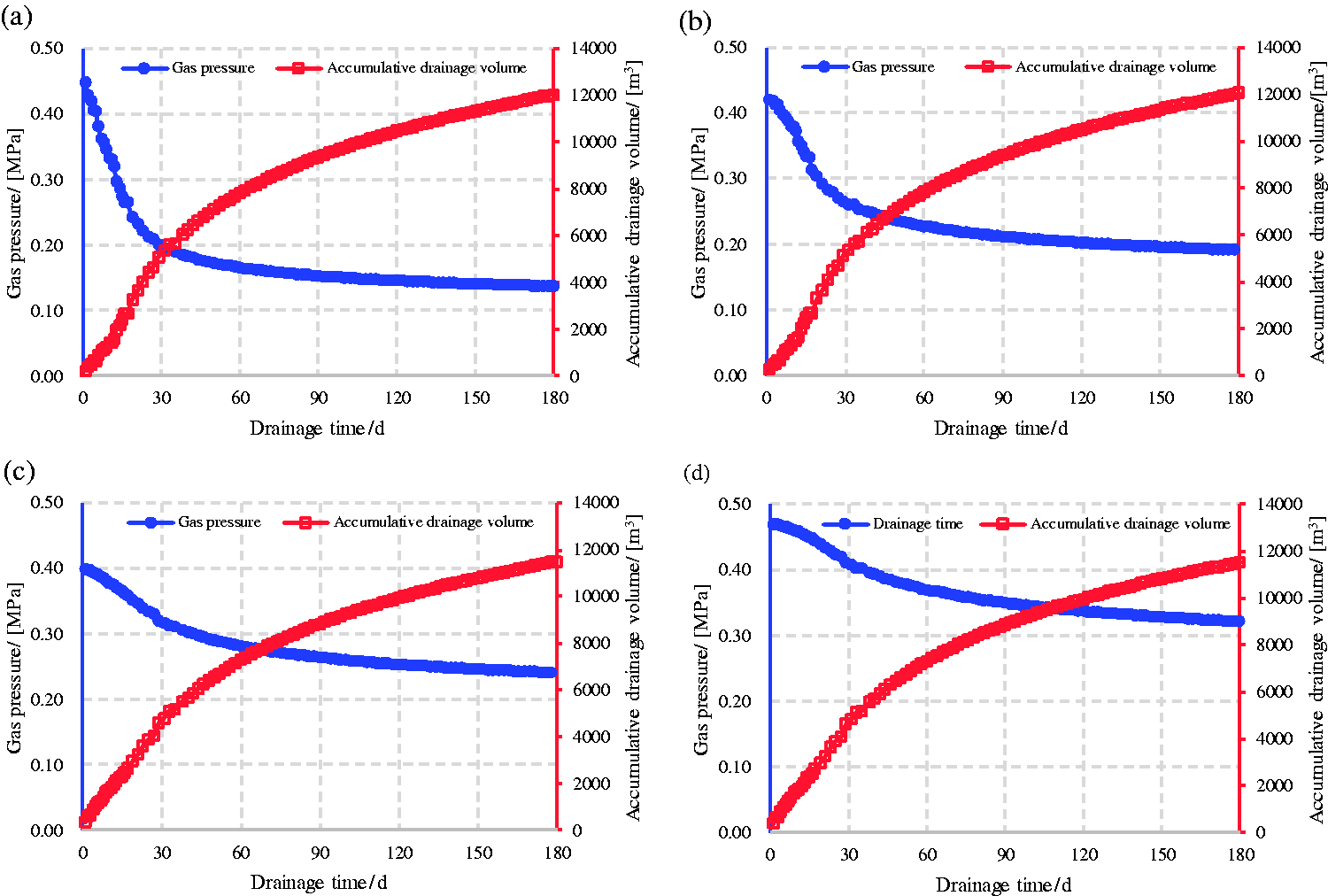
Curves of gas pressure in pressure-measuring borehole and accumulative gas drainage volume from corresponding drainage borehole: (a) pressure-measuring borehole #1; (b) pressure-measuring borehole #2; (c) pressure-measuring borehole #3; and (d) pressure-measuring borehole #4.
Measurement results obtained using the gas flow method
It was assumed that the gas drainage rate near borehole was 1 and that at infinity from borehole was 0, as shown in Figure 6.
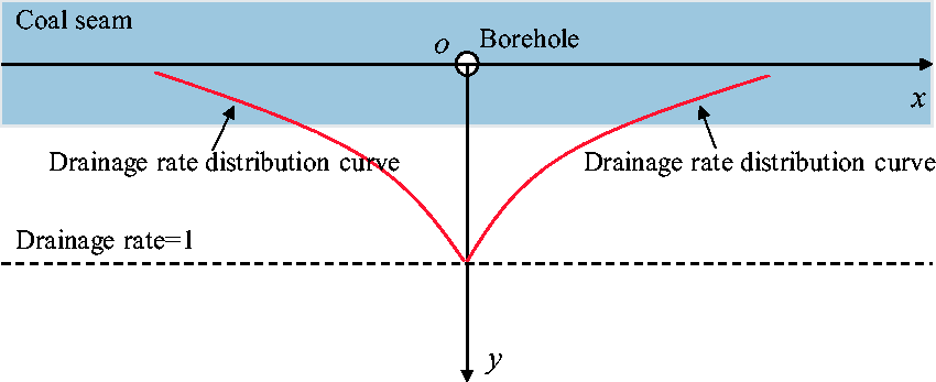
Distribution law of gas drainage rates around drainage borehole.
It was assumed that the gas drainage rates on both sides of a drainage borehole followed exponential distribution, the gas drainage rates on both sides of a drainage borehole could be expressed as follows

The gas drainage volume from a drainage borehole could be expressed as follows

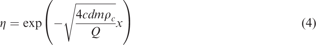
By finding the limit after integration, the expression of coefficient β was obtained as follows
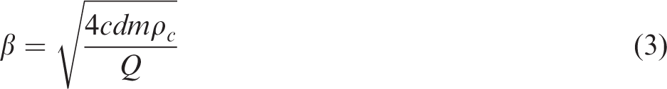
The gas drainage rate at x, m, from the borehole along the coal seam was
Based on the accumulative gas volumes from drainage borehole at different drainage times (Figure 5), and with equation (4), the curves of gas drainage rate at 0.75 m, 1.5 m, 2.25 m, and 3 m from drainage borehole were obtained, as shown in Figure 7.
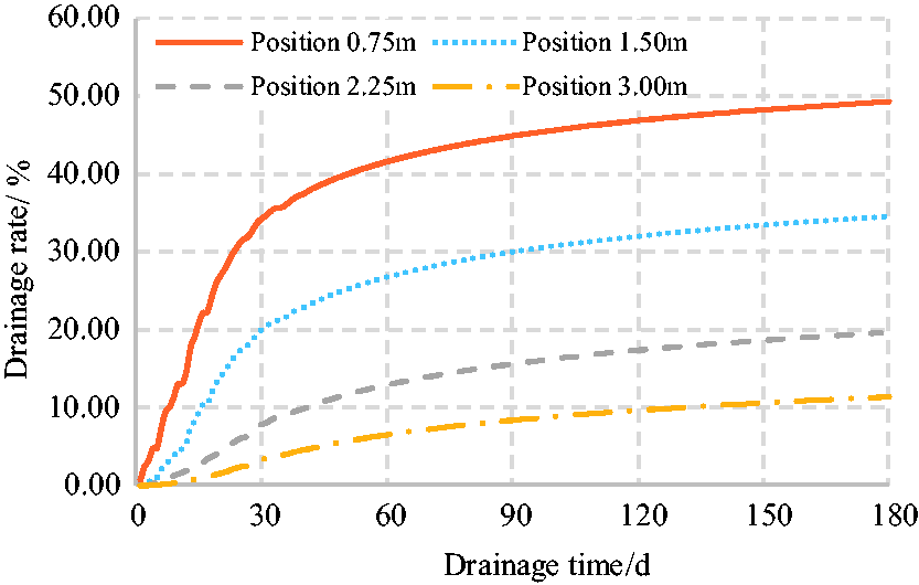
Curves of gas drainage rate at different distances from drainage borehole.
As can be seen from Figure 7, with the extension of drainage time, the gas drainage rates at various points increase constantly, and the increase amplitudes of drainage rate decrease constantly. Twenty-six days after drainage from the drainage borehole #1, the gas drainage rate at 0.75 m from the drainage borehole #1 reached 30%. At this moment, this position was located within the effective drainage radius of the drainage borehole #1, and the drainage time was extremely close to that (27 days) obtained using the gas pressure method. Ninety days after drainage from the drainage borehole #1, the gas drainage rate at 1.5 m from the drainage borehole #1 reached 30%. At this moment, this position was located within the effective drainage radius of the drainage borehole #1, and the drainage time was very close to that (92 days) obtained using the gas pressure method. One hundred and eighty days after drainage from the drainage borehole #2, the gas drainage rates at both 2.25 and 3 m from the drainage borehole #2 did not reach 30%; hence, the coal masses at both 2.25 and 3 m from the drainage borehole #2 did not enter the effective drainage radius of the drainage borehole #2. Therefore, the effective drainage radius of the borehole along coal seam #9 was 0.75 m, 26 days after drainage, and 1.5 m, 90 days after drainage, and the calculation results obtained using the gas flow method agree with the measurement results obtained using the gas pressure method.
Experimental study on methane seepage in coal masses around borehole
However, in the currently established models for gas flow around borehole, the influence of the change in stress in coal masses around borehole on the permeability of coal mass has not been taken into account, and solid–gas functional relationship between stress and permeability of coal mass around the borehole has not been established; hence, the numerical calculation results differ relatively greatly from the actual situations. In order to obtain the stress–permeability functional relationship of coal masses around borehole, experimental schemes were designed according to the whole process of evolution of the stresses in the coal masses around borehole, and then experiment of solid–gas coupling seepage in the coal masses around borehole was conducted.
Preparation of the experiment
Experimental apparatus
The triaxial servo-controlled seepage experiment machine for thermo-fluid–solid coupling of the coal seam containing methane is a rigid experimental machine used to study the laws of methane seepage and coal rock deformation and failure. The machine consists of five principal parts: an axial compression system, a lateral pressure system, a methane input system, a methane flow rate measurement system, and a computer control system. The principle of the experimental device is shown in Figure 8. This device can simulate methane seepage from coal rock under different geostresses, different methane pressures, and different ambient temperatures.
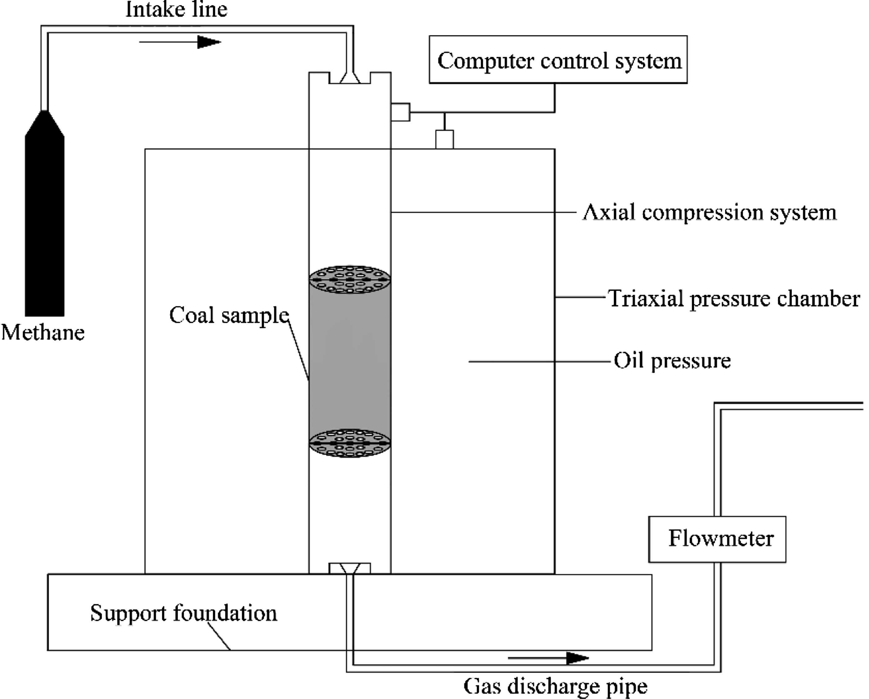
Schematic diagram of the experimental device.
Preparation of coal samples
The coal samples were taken from the 9712 working face in the Kaiyuan Coal Mine. Each sample had a diameter of 50 mm and a length of 100 mm. The prepared coal samples are shown in Figure 9.
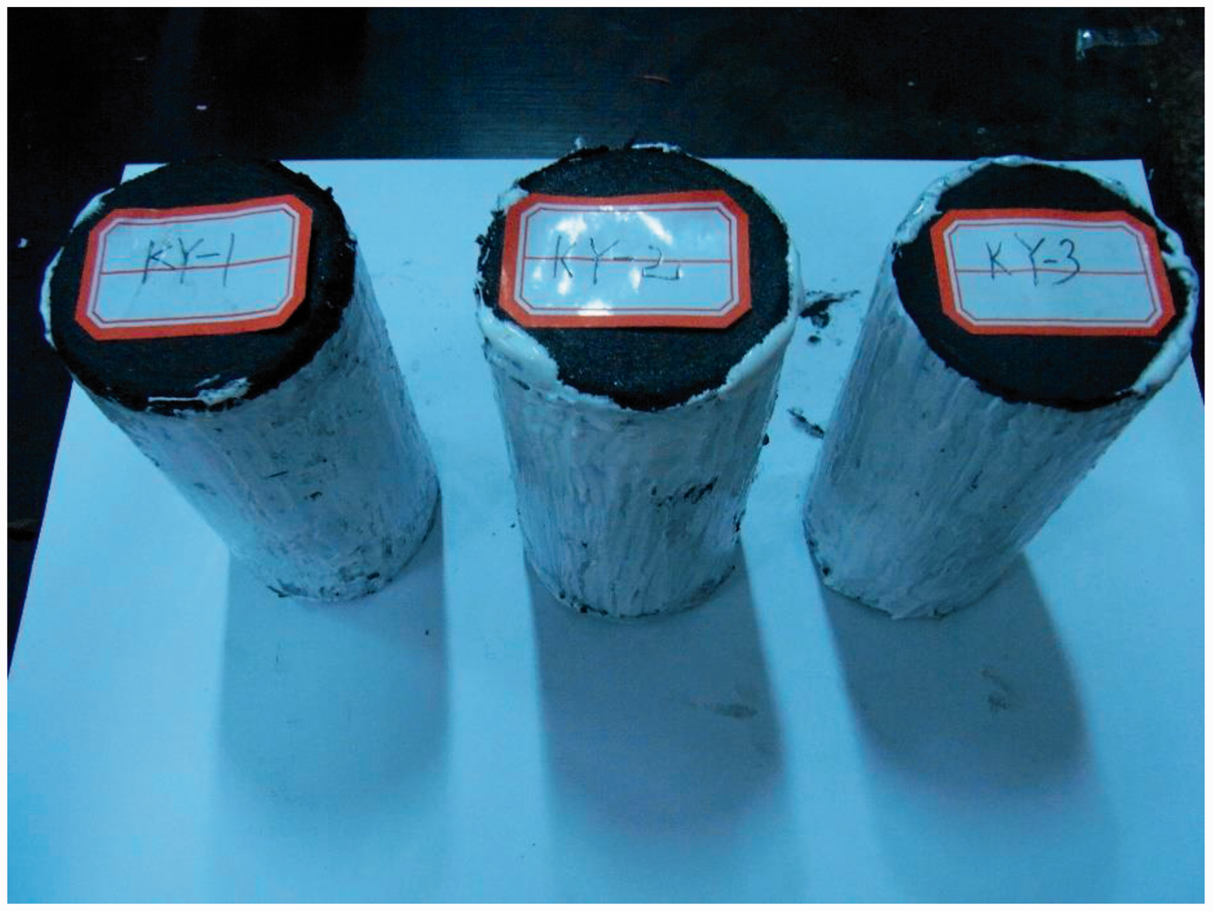
Coal samples from the 9712 working face in the Kaiyuan Coal Mine.
Experimental schemes and methods
When coal is drilled, the horizontal stress around the borehole exhibits a relief process (Qian and Shi, 2003), whereas the vertical stress of coal masses experience an in situ stress stage, a stress loading stage, and stress-relief stage (Figure 10).
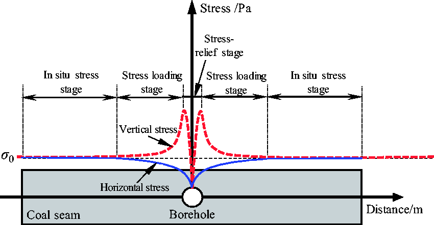
Stress in the coal mass around the borehole along the coal seam.
Based on the entire evolution of the stress around the borehole along the coal seam, the experimental scheme was designed as follows.
The starting point of vertical stress unloading in this experiment was set as 15 MPa. The starting point of horizontal stress unloading in this experiment was calculated by using the generalized Hooke’s law

A uniaxial compression test on coal sample KY-1 had been conducted previously, and the results gave a Poisson’s ratio for coal sample KY-1 of 0.28. When σz = 15 MPa, σx = 5.83 MPa. Therefore, the starting points of horizontal stress unloading in this experiment were set as 5 and 6 MPa, and it was assumed that the horizontal stress and the vertical stress decreased simultaneously. In this experiment, the unloading speeds of both horizontal stress and vertical stress were 0.008 MPa/s. The gas pressure in this experiment was 0.45 MPa based on the actual conditions at the 9712 working face.
To isolate the oil path and gas path, a specimen coated with silicone rubber and enclosed within a heat shrinkable tube was put into the seepage experiment machine. Vertical stress was applied slightly first, to press the specimen, then oil was injected to remove the air in the pressure chamber, and the oil return valve was closed. First, the horizontal stress was applied at a rate of 0.008 MPa/s to a preset value (5 and 6 MPa). The pressure relief valve of the methane cylinder was adjusted to keep the methane pressure stable at 0.45 MPa, and the methane pressure was maintained for 24 h (Jiang et al., 2010) so that the coal sample fully adsorbed the methane. Then the methane pipeline valve was opened; after the flow rate stabilized, the methane flow rate was recorded. The horizontal stress was fixed at 5 or 6 MPa, and the vertical stress was applied at a rate of 0.008 MPa/s to reach the preset value (15 MPa). Then the vertical stress and the horizontal stress were unloaded simultaneously at a rate of 0.008 MPa/s, until the coal sample was destroyed. During the loading and unloading processes, recordings were made at 0.5 MPa intervals in vertical stress. Stress load and unloading paths are shown in Figure 11.
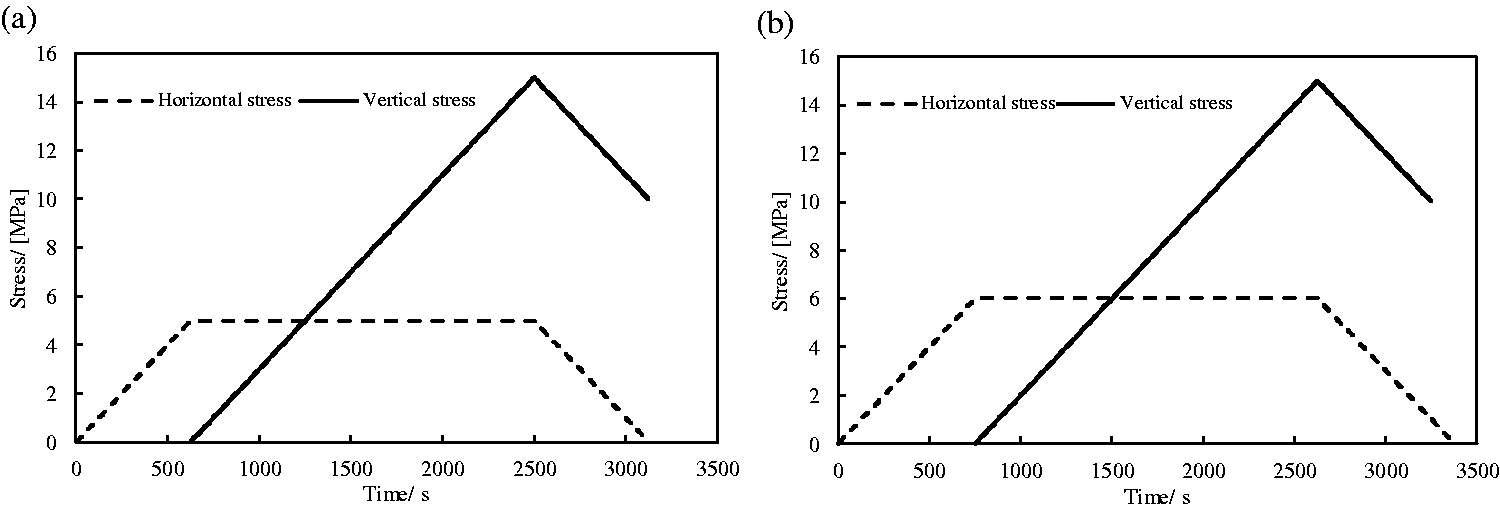
Loading and unloading paths of stress for coal samples: (a) coal sample KY-2 (horizontal stress of 5 MPa) and (b) coal sample KY-3 (horizontal stress of 6 MPa).
Analysis of experimental results
Stress–strain curves reflecting the entire evolution of the stress around the borehole were obtained by collating the experimental results, as shown in Figure 12.
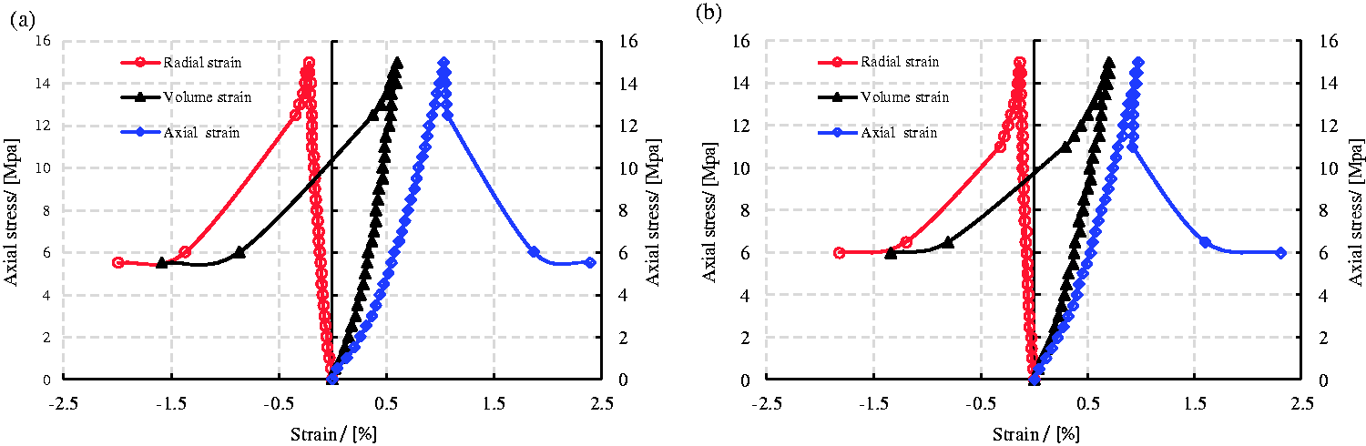
Deformation and failure laws for coal samples: (a) coal sample KY-2 (horizontal stress of 5 MPa) and (b) coal sample KY-3 (horizontal stress of 6 MPa).
It can be seen from Figure 12 that, during the initial vertical stress loading period, the coal sample underwent axial compaction with internal pore fractures being closed. The coal sample’s stress–strain relationship was nonlinear at the initial loading stage but exhibited good linearity during the following loading stage. During the entire unloading of vertical stress and horizontal stress, the coal rock experienced three stages, i.e. strain rebound, strain increase, and strain softening. The strain rebound stage occurred at the beginning of the unloading stage, during which the strain of the coal sample decreased and the coal sample tended to constantly return to its original state. With the continuous unloading of the vertical stress and the horizontal stress, the strain rebound gradually disappeared, the rate of lateral strain increased, the coal sample dilated, primary fractures in the coal rock were changed from being compressed to being expanded, and new fractures were generated constantly. When the vertical stress of coal sample KY-2 was unloaded to 12.5 MPa and the horizontal stress was unloaded to 2.5 MPa, a sudden stress drop occurred in the coal sample, and the coal sample went into the strain softening stage. When the vertical stress of coal sample KY-3 was unloaded to 11.0 MPa and the horizontal stress was unloaded to 2.0 MPa, a sudden stress drop occurred in the coal sample, and the coal sample went into the strain softening stage.
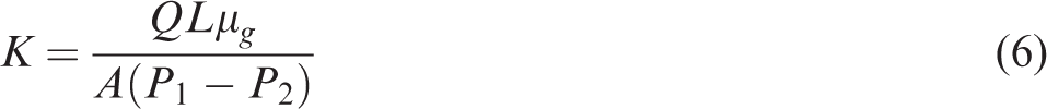
Permeability is an important parameter for analyzing the solid–gas coupling law. According to Darcy’s law, the permeability K (in m2) of a sample can be expressed as (Tang et al., 2006a, 2006b)
The variation in permeability of coal rock is closely related to its deformation and damage. It can be seen from Figure 13 that, during the vertical stress loading process at fixed horizontal stress (5 and 6 MPa), the methane flow channels were closed, and hence the permeability of coal rock gradually decreased and the methane flow rate also decreased. At the initial unloading stage of vertical stress and horizontal stress, the slow volume expansion of the coal rock was mainly caused by the gradual recovery of the compressed pores in the coal rock, with the permeability of the coal rock slightly increasing. The continuous decrease in vertical stress and horizontal stress strengthened the expansion of the coal rock. With the expansion of primary pore fractures and the occurrence of new pore fractures, the permeability of coal rock increased rapidly. When the horizontal stress dropped to a certain extent, a sudden stress drop occurred, and macrofractures were produced in the coal sample after tensile–shear failure occurred, resulting in a sharp increase in permeability of the coal sample.
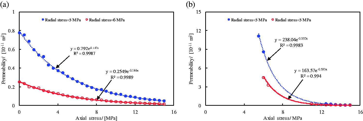
Variation of methane seepage in the coal sample during (a) the loading stage and (b) the unloading stage.
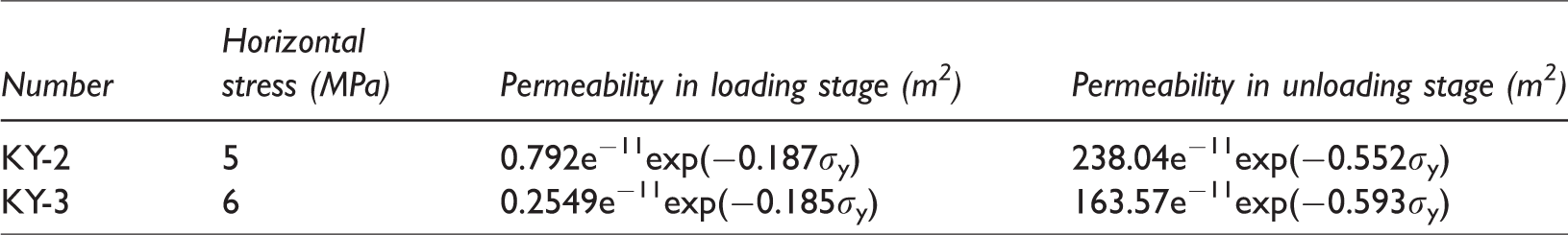
The experimental data were fitted with an exponential function, and the fitting relationships between the permeability and vertical stress of the coal samples at the loading stage and unloading stage are listed in Table 1.
Fitting relationships between the permeability and volume strain of the coal samples.
CFD simulation study on influential factors for drainage radius of the borehole along the coal seam being worked
Drainage time, initial gas pressure, borehole diameter, and drainage negative pressure are potential influential factors for the effective drainage radius of the borehole along the coal seam in coal seam being worked. Consequently, in this paper, numerical simulation was conducted for the influences of the above influential factors on the effective drainage radius of the borehole along the coal seam, so as to find main influential factors for the effective drainage radius of the borehole along the coal seam, providing theoretical guidance to optimization design of layout parameters for the boreholes along the coal seam in the Kaiyuan Coal Mine. The software used in this numerical simulation was COMSOL Multiphysics, which is an excellent multi-physical field coupling software. The horizontal permeability of a coal seam was not completely identical to the vertical permeability of the coal seam. Wang et al. (2018) acquired raw coal samples along different directions and conducted seepage experiments of the samples, and the experimental results show that when the effective stress of coal mass is more than 5 MPa, the horizontal permeability of the coal mass tends to be consistent with the vertical permeability of the coal mass. The effective stress in this simulation was far more than 5 MPa; hence, it could be believed that the horizontal permeability of the coal mass was identical to the vertical permeability of the coal mass.
The model coupled gas flow and deformation of the coal seam
This model coupled gas flow and deformation of the coal seam was based on some assumptions as follows: (a) the coal is considered as homogenizing isotropic body; (b) the coalbed methane is considered as ideal gas; (c) the coal is only saturated by the coalbed methane; and (d) the process of coupled gas flow and deformation of the coal seam is considered as isothermal.
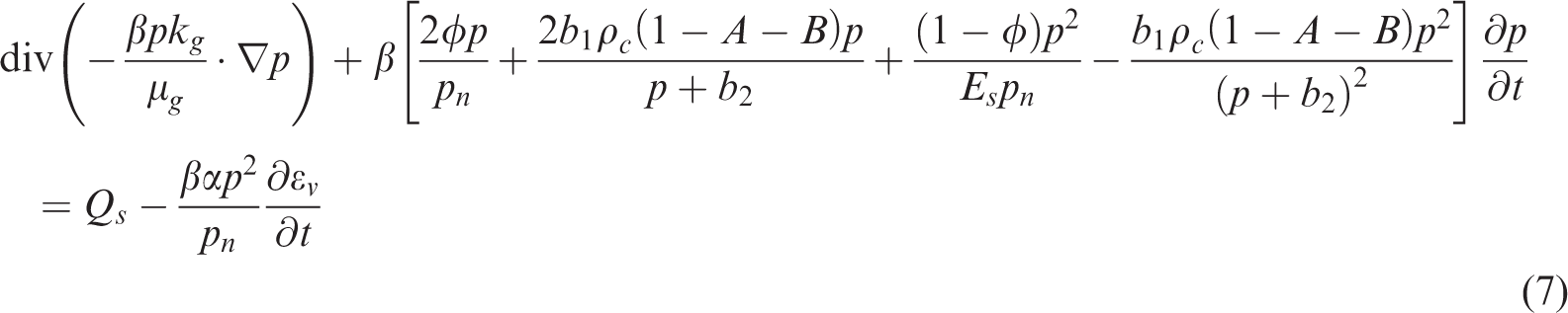
Seepage control equation for methane-bearing coal mass
Hu et al. (2011) derived a seepage control equation for methane-bearing coal mass based on the kinematic equation of methane seepage in the coal seam, the continuity equation of methane seepage in the coal seam, the gas state equation of methane in the coal seam, and the equation of methane content in the coal seam, together with the rate of variation in porosity of coal mass versus time in isothermal process
In equation (7), φ is the porosity of coal and can be expressed as (Hu et al., 2012)

Stress equilibrium equation
It is assumed that just small deformation occurs in the solid–gas coupled coal so that it can be assumed to be linear elastic medium. Hence, the stress equilibrium equation of this solid–gas coupled medium can be expressed as

Therefore, the governing equation of the model coupled gas flow and deformation of the coal seam in co-extraction of coal and coal bed methane (CBM) can be obtained by coupling equations 7 to 9.
The numerical simulation uses two modules of COMSOL Multiphysics: the “Solid Mechanics module”, and the “partial differential equation (PDE) module”. The solid mechanics module is used to solve the control equation of deformation of coal mass (equation (9)), and plastic solution option is added on the basis of linear elastic module; thus, the module can be used to solve the plastic deformation occurring in the coal masses around borehole. The PDE module is used to solve the seepage control equation for methane-bearing coal mass (equation (7)), and the functional relationship between permeability and vertical effective stress in Table 1 is used for assigning value to permeability. Because the horizontal stress calculated by using the generalized Hooke’s law is closer to 6 MPa, the relationship between permeability and the axial stress of the calculation area was determined based on experimental results from coal sample KY-3.
Geometric model and boundary conditions
Based on the occurrence of the 9712 working face and the layout of the boreholes, a geometric model was established, as shown in Figure 14.
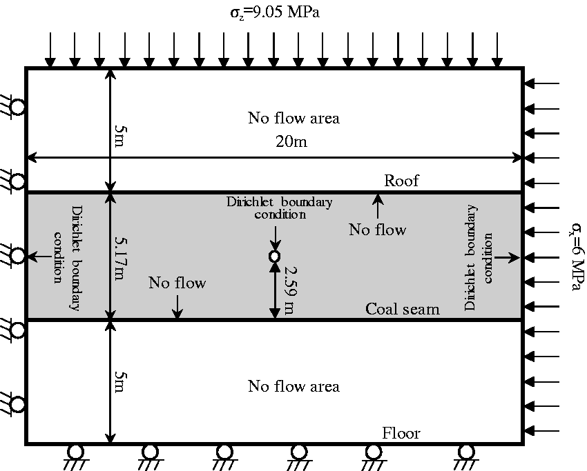
Geometric model and boundary conditions.
The calculation model had a height of 15.17 m and a length of 20 m. The thickness of the roof and the floor are 5 m, respectively, and the upper rock layer with a thickness of 362 m in the model was converted into a uniform load of 9.05 MPa applied to the top interface of the model. The borehole diameter and drainage negative pressure are 0.12 m and 10 kPa, respectively. In the fluid calculation, the right and the left boundary of the coal seam were set as the pressure inlet; and the borehole was set as the pressure outlet. The upper and lower boundaries of the coal seam were set as no flow boundaries. According to the field measurement of gas pressure at the 9712 working face, the left and right boundaries were set as pressure boundaries (0.45 MPa), and the borehole outlet was set to 0.09 MPa (negative pressure 10 kPa). The left boundary of the model can move up and down but cannot move left and right; the lower boundary of the model can move left and right but cannot move up and down; and the upper and right boundaries of the model can move freely.
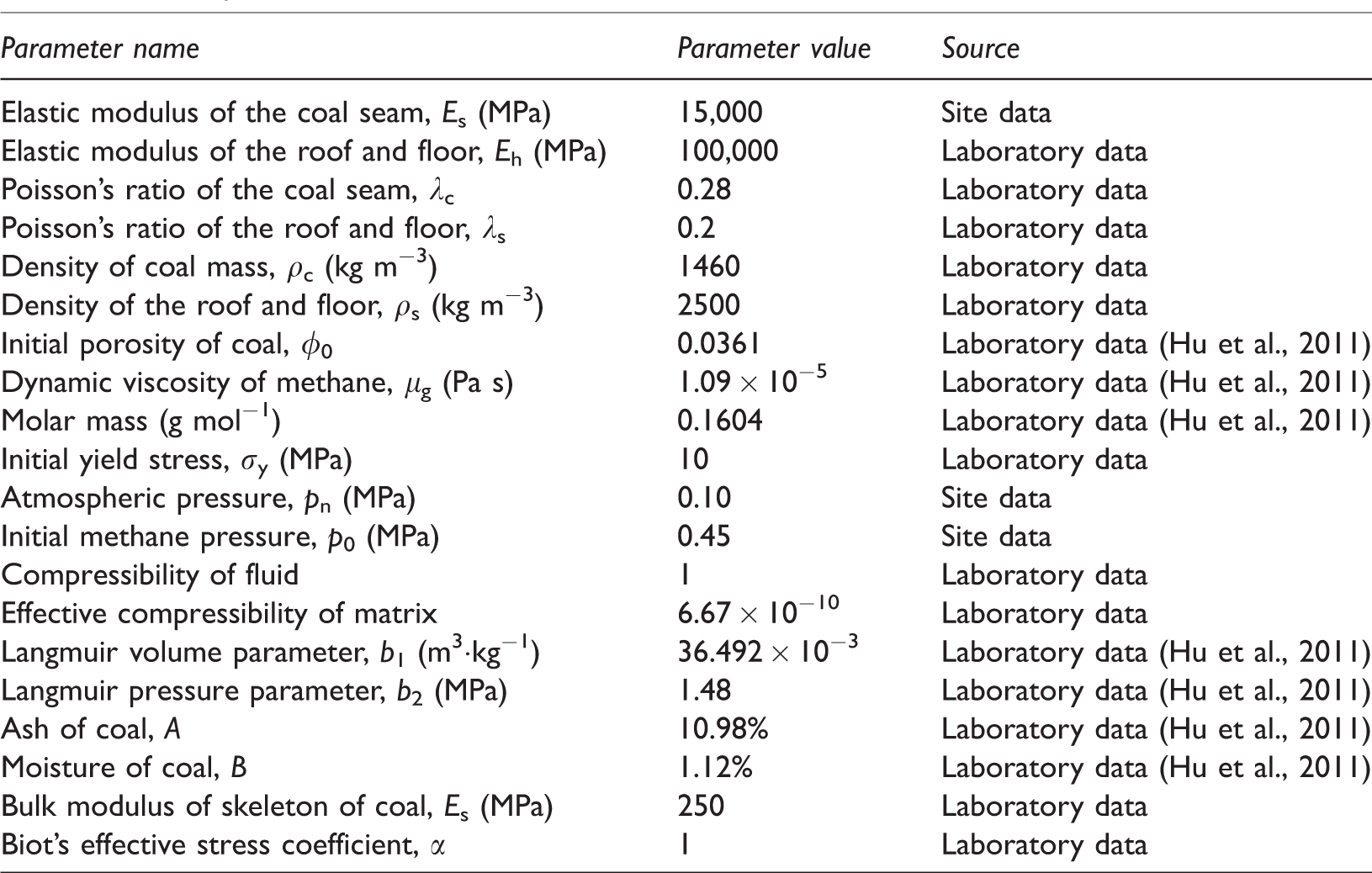
This model can simulate the influence of drainage time, gas pressure, borehole diameter, and the suction pressure on methane seepage around borehole by enabling the boundary conditions to be changed. The model parameters are listed in Table 2.
Model parameter values.
Analysis of simulation results
After the borehole construction was completed, the initial permeability values of the coal masses around the borehole along the coal seam are shown in Figure 15. As can be seen from Figure 15, owing to decrease in stress in the coal masses around the borehole along the coal seam, plastic failure occurred in the coal masses and the permeability values of the coal masses were increased significantly. The initial permeability values at the left and right boundaries of the coal seam not influenced by borehole drilling were 5.1846 × 10⁻¹³ m2, the maximum initial permeability occurred at borehole wall (3.8046 × 10⁻¹¹ m2), and the minimum initial permeability occurred at 0.12 m from the borehole center (2.8324 × 10⁻¹³ m2). Influenced by the borehole construction, the permeability in the plastic zone was increased by 133.3 times.
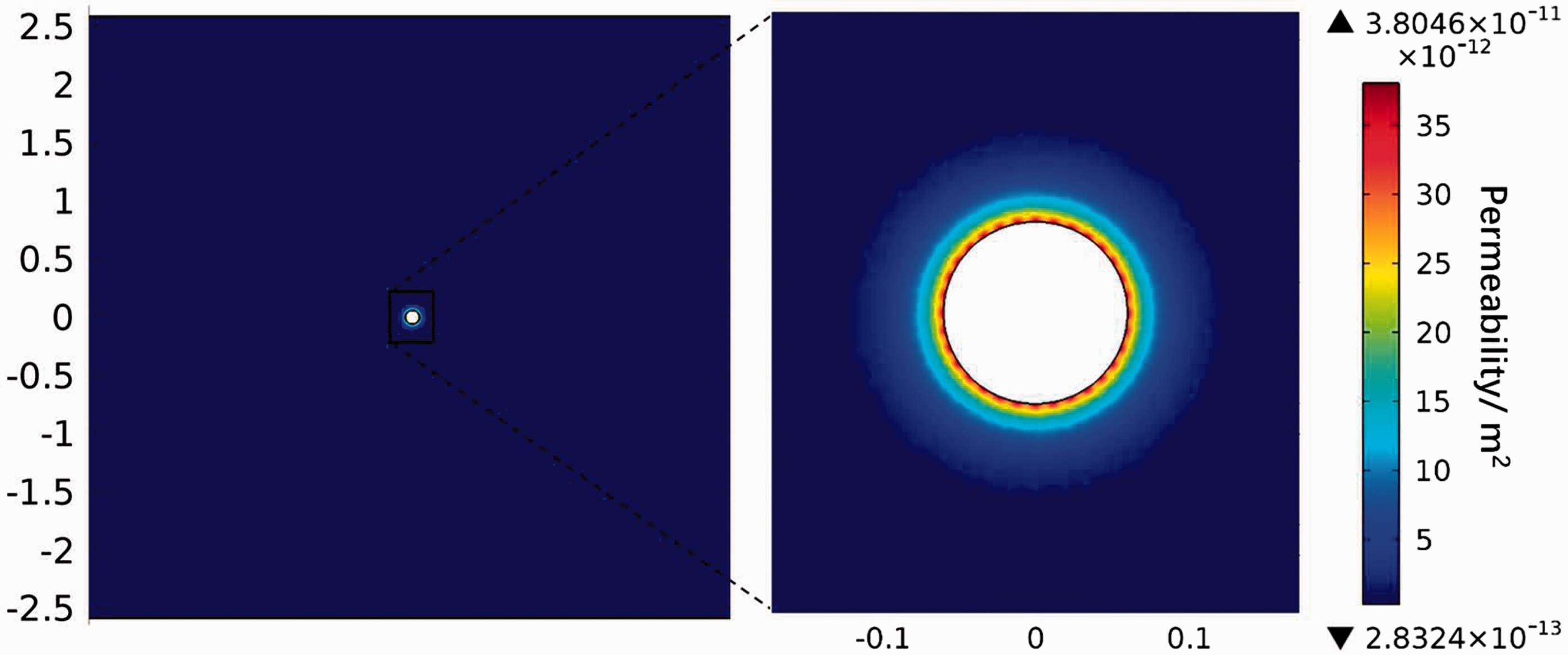
Distribution contour diagram of initial permeability values of coal masses around borehole.
A base model was established based on the layout parameters and gas drainage parameters for the boreholes along the coal seam at the 9712 working face in the Kaiyuan Coal Mine, and the effective drainage radius of the borehole along the coal seam was calculated for 30, 60, 90, 120, 150, and 180 days after drainage. The calculation results are shown in Figure 16.
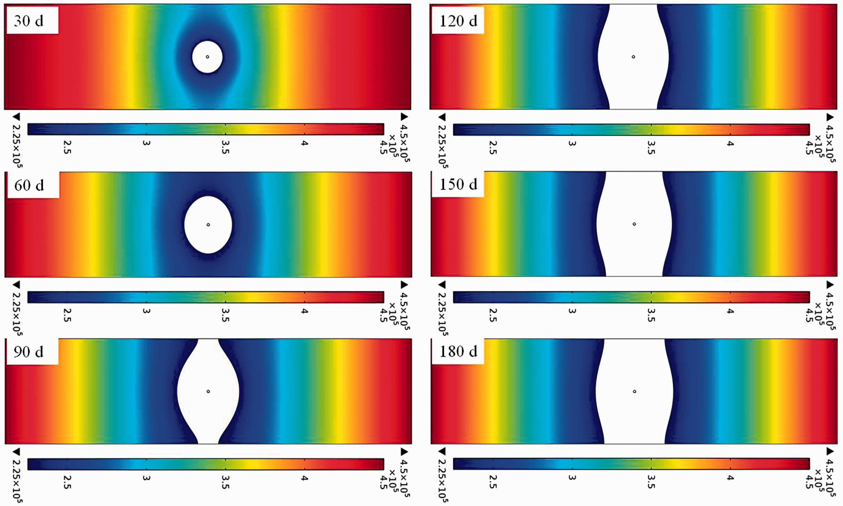
Effective drainage radius of the borehole along the coal seam at different drainage times.
As can be seen from the figure, with the extension of drainage time, the effective drainage radius of the borehole along the coal seam increases constantly; however, when the drainage time is more than 180 days, the effective drainage radius of borehole basically does not increase. With the extension of drainage time, the gas pressure gradient around borehole declines, and the gas flow speed decreases, and hence the increase amplitude of effective drainage radius of borehole decreases constantly. Moreover, comparative analysis between the numerical simulation results and the on-site measurement results was conducted (Figure 17), and the simulation results agree quite well with the measurement results, indicating that the model established in this paper conforms to the actual situations on the site and the calculation results of other simulation solutions based on this model are credible.
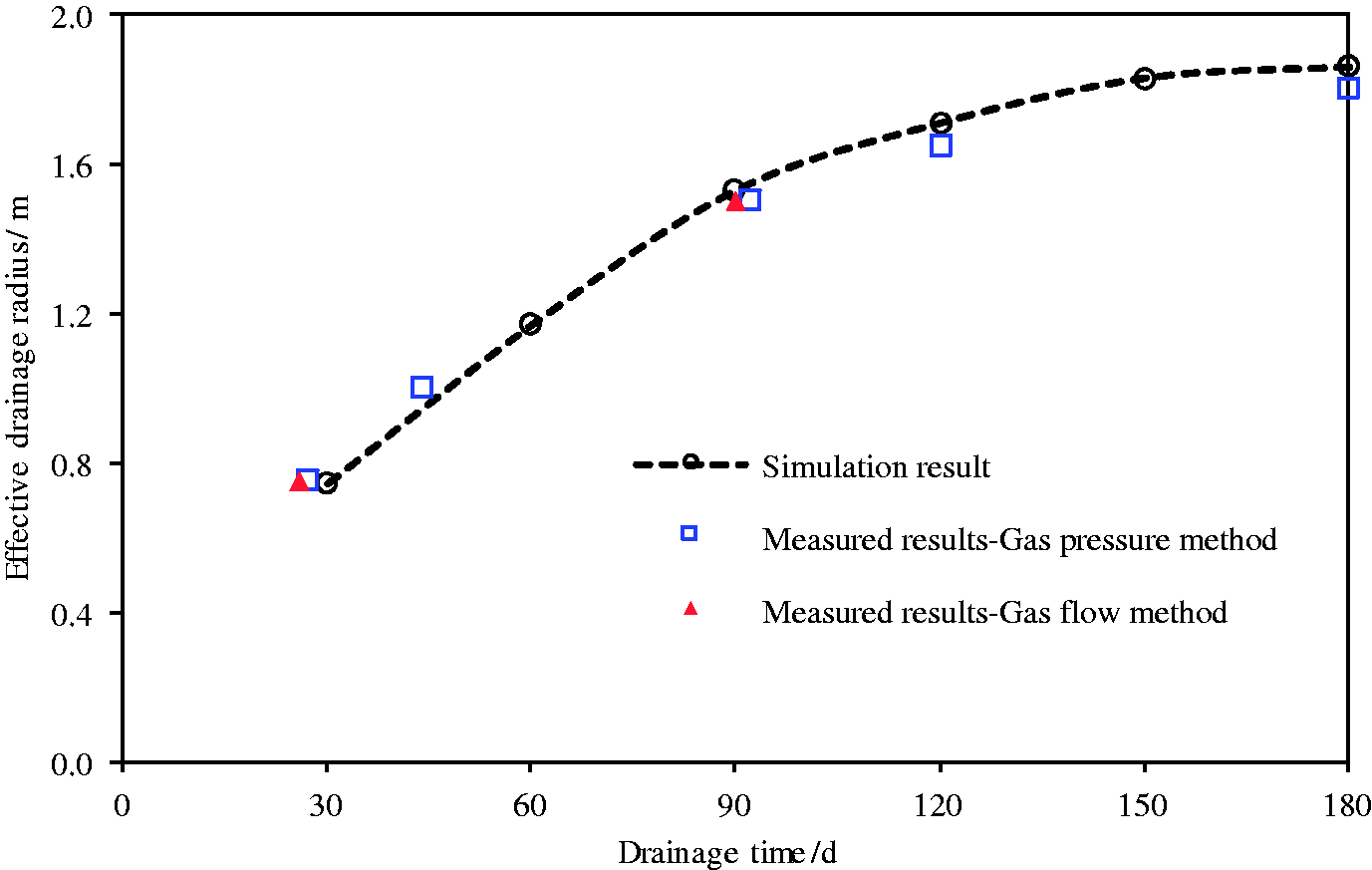
Comparative analysis between numerical simulation results and on-site measurement results.
In this paper, numerical calculation was conducted for the influences of the above factors on the effective drainage radius of the borehole along the coal seam by changing initial gas pressure, borehole diameter, and drainage negative pressure (with drainage time of 180 days). The initial gas pressure was set as 0.30, 0.45, 0.60, and 0.75 MPa; the borehole diameter was set as 90, 120, 150, and 180 mm; and the drainage negative pressure was set as 5, 10, 15, and 20 kPa.
With the decrease in gas pressure to 51% as determining criterion for effective drainage radius of the borehole the along coal seam, the effective drainage radius of the borehole along the coal seam at different initial gas pressures can be obtained, as shown in Figure 18(a). As can be seen from Figure 18(a), initial gas pressure has significant influence on the effective drainage radius of borehole, and the larger the initial gas pressure, the larger the effective drainage radius of borehole. When the initial gas pressure increases from 0.30 MPa to 0.75 MPa, the effective drainage radius of borehole increases from 1.08 m to 2.58 m, which is an increase of 139%. The larger the initial gas pressure, the larger the gas pressure gradient around borehole, and the higher the gas flow speed, and hence the larger the effective drainage radius of borehole will be at identical extraction condition. However, in the initial gas pressure increasing process, the increase amplitude of the effective drainage radius of borehole decreases constantly.
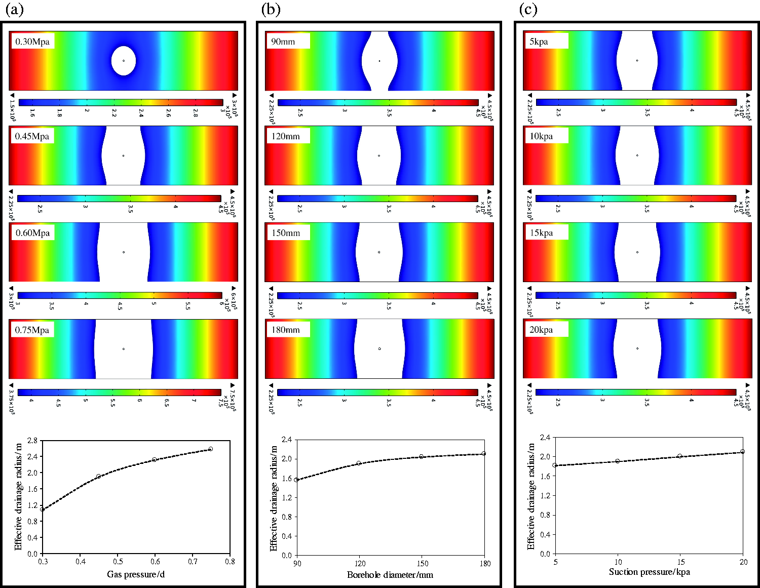
Effective drainage radius of the borehole along the coal seam at (a) different gas pressures, (b) different borehole diameters and (c) different drainage negative pressures.
Similarly, with the decrease in gas pressure to 51% as determining criterion for effective drainage radius of the borehole along the coal seam, the effective drainage radius of the borehole along the coal seam at different borehole diameters can be obtained, as shown in Figure 18(b). As can be seen from Figure 18(b), the effective drainage radius of the borehole increases constantly with the increase in borehole diameter. However, in the borehole diameter increasing process, when the borehole diameter increases from 120 to 180 mm, the effective drainage radius of borehole increases from 1.9 to 2.1 mm, which is only an increase of 10.5%; in other words, the increase amplitude of the effective drainage radius of borehole is relatively small. Hence, the effect of increase in borehole diameter on the increase in effective drainage radius is limited. Furthermore, blindly increasing borehole diameter will not only increase the construction cost but also increase the probability of borehole collapse, raising the difficulty in borehole supporting. Consequently, the designed diameter (120 mm) of the borehole along the coal seam in the Kaiyuan Coal Mine is reasonable, it is not necessary to increase the borehole diameter for the increase in effective drainage radius.
Similarly, with the decrease in gas pressure to 51% as determining criterion for effective drainage radius, the effective drainage radius of the borehole along the coal seam at different drainage negative pressures can be obtained, as shown in Figure 18(c). As can be seen from Figure 18(c), the effective drainage radius of the borehole increases linearly with drainage negative pressure. When the drainage negative pressure increases from 5 to 20 kPa, the effective drainage radius of borehole increases from 1.82 to 2.09 m, which is only an increase of 14.8%; in other words, the increase amplitude of the effective drainage radius of borehole is not large. Thus, it can be seen that the effect of increase in negative pressure in borehole on the increase in effective drainage radius is limited. In addition, high negative pressure will not only raise the running pressure of pump station but also increase the gas leakage rate from borehole, decreasing the gas extraction concentration from the coal seam being worked.
In summary, the reasonable drainage time, reasonable borehole diameter, and reasonable drainage negative pressure are 180 days, 120 mm, and 15 kPa, respectively, for the boreholes along the coal seam in coal seam #9 of the Kaiyuan Coal Mine.
Conclusions
A measurement study was conducted for the effective drainage radius of the borehole along coal seam #9 of the Kaiyuan Coal Mine using the gas pressure method. In the measurement process, a multi-stage segmented borehole-sealing method was proposed. The measurement results obtained using the gas pressure method show that the effective drainage radius of the borehole along coal seam #9 is 0.75 m, 27 days after drainage, and 1.5 m, 92 days after drainage. Moreover, the effective drainage radius of the borehole along coal seam #9 was calculated using the gas flow method, and the calculation results show that the effective drainage radius of the borehole along coal seam #9 was 0.75 m, 30 days after drainage, and 1.5 m, 90 days after drainage, and the calculation results agree with the measurement results obtained using the gas pressure method. Experimental schemes were designed for the entire evolution of the stress in the coal mass around borehole, and an experimental study on methane seepage in the coal masses around borehole was conducted. The experimental results show that, during simultaneous unloading of the axial pressure and confining pressure, the coal sample experienced three stages, i.e. strain rebound, strain increase, and strain softening. When the confining pressure dropped to a certain extent, a sudden stress drop occurred in the coal rock, and macrofractures were produced after tensile–shear failure occurred in the coal rock, resulting in an abrupt change in permeability of the coal rock and a dramatic increase in the methane flow rate. Fitting functions for the permeability of the coal sample and vertical stress in the coal sample at the pressure loading and unloading stages were obtained by fitting the experimental data. Based on the vertical stress–permeability functional relationship of coal masses around borehole, a numerical calculation model for methane seepage from coal masses around borehole was established, and the influences of drainage time, initial gas pressure, borehole diameter, and drainage negative pressure on the effective drainage radius of borehole were investigated. The numerical simulation results show that drainage time, initial gas pressure, and borehole diameter are main factors influencing the effective drainage radius of borehole. With the increase in drainage time, initial gas pressure, and borehole diameter, the effective drainage radius of borehole increases continuously but its increase amplitude decreases constantly. Drainage negative pressure has relatively small influence on the effective drainage radius of borehole. With the increase in drainage negative pressure, the effective drainage radius of borehole increases linearly but the increase amplitude is relatively small. The reasonable drainage time, reasonable borehole diameter, and reasonable drainage negative pressure are 180 days, 120 mm, and 15 kPa, respectively, for the borehole along the coal seam in coal seam #9 of the Kaiyuan Coal Mine.
Footnotes
Declaration of conflicting interests
The author(s) declared no potential conflicts of interest with respect to the research, authorship, and/or publication of this article.
Funding
The author(s) disclosed receipt of the following financial support for the research, authorship, and/or publication of this article: Financial support for this work was provided by Fundamental Research Funds for the Central Universities (No. 2015XKMS093) and Priority Academic Program Development of Jiangsu Higher Education Institutions (No. SZBF2011-6-B35).