
Abstract
With the rapid progress of petroleum engineering, liquid nitrogen jet is expected to be used for perforation and jet fracturing, and then provide a new method for unconventional reservoirs efficient development. In order to research the flow field characteristics and evaluate the impact capability of liquid nitrogen jet, a computation fluid dynamic model was built by coupling the nitrogen physical property equations to simulate the flow field of liquid nitrogen jet. The results indicated that given the same simulation conditions, the impact pressure of liquid nitrogen jet was equivalent to that of water jet. The liquid nitrogen jet presented more excellent impact capability than water jet because of its higher axial and radial velocities. The impact capability of liquid nitrogen jet increased with the growth of nozzle pressure drop and nozzle diameter, decreased with the increasing of standoff distance, and was slightly influenced by fluid temperature. The confining pressure hardly affected the impact capability of liquid nitrogen jet, so it can be neglected in the engineering application. This study uncovered the flow field characteristics of liquid nitrogen jet and could provide theoretical guidance for the application of perforation and fracturing with liquid nitrogen jet.
Introduction
In petroleum engineering, the high pressure water jet has played an important role in drilling and fracturing because it can be used to break and fracture the formation rock efficiently (Huang et al., 2008, 2015; Li et al., 2014). However, as the petroleum industry moves into unconventional reservoirs, such as shale gas, the relevant technologies which use water-based work fluid have to face many challenges (Hou et al., 2017). The unconventional formation is usually very tight and has extremely narrow seepage channel, the issues of water sensitivity and water block damage are easily generated (Ali et al., 2013; Bahrami et al., 2012). The water-based fluid has large amounts of chemical components, which are like to pollute the surface and underground water resources (Holtsclaw et al., 2011). Moreover, a great amount of water is usually consumed during the development of unconventional reservoir. Take the shale gas example; over 10,000 m3 of water is cost during fracturing a single shale gas well (Arthur et al., 2009). This undoubtedly intensifies the water shortages in arid regions. In this case, waterless development has been an important tendency for unconventional reservoirs. Thus, a novel substitute for water-based fluid in jet is also becoming increasing significant.
Liquid nitrogen is a colorless, tasteless and extremely inert fluid, which has been an important work fluid in oil and gas development (Shouldice, 1964). The problems of reservoir damage, water pollution and water consumption are expected to be solved perfectly if the liquid nitrogen is used as the work fluid (Wang et al., 2016). In addition, the liquid nitrogen can sharply reduce the temperature around the rock because of its extremely cryogenic temperature (Cai et al., 2015a). The cryogenic nitrogen can produce great thermal shock to rock and then promote the open of natural fractures or the generation of new fractures (Alqatahni et al., 2016; Cai et al., 2016), which can theoretically help to improve the rock breaking efficiency of liquid nitrogen jet. In view of the unique properties of liquid nitrogen, some researchers have explored the feasibility of drilling and fracturing with liquid nitrogen jet. Huang et al. (2016) proposed that liquid nitrogen is expected to be an excellent substitute for water based work fluid in petroleum engineering, especially in geothermal drilling and reservoir fracturing. They also conducted some fundamental investigations such as rock breaking with liquid nitrogen jet and heat transfer between liquid nitrogen and rock to analyze the feasibility of drilling and fracturing with liquid nitrogen jet. Cai et al. (2015b, 2016) indicated that the liquid nitrogen jet would present larger jet velocity, better performance in particles acceleration and greater pressure boosting in perforation cavity than water jet if it was used in reservoir fracturing. Li et al. (2016) and Huang et al. (2016) researched the coal breaking with liquid nitrogen jet by the self-designed apparatus. The experimental results showed that the tensile stress caused by liquid nitrogen cooling could aid in the coal breaking. And under the same experimental conditions, liquid nitrogen jet presented better coal breaking performance and lower energy consumption than water jet. In conclusion, liquid nitrogen jet is a waterless technology which uses liquid nitrogen as the jet medium. Due to its inert characteristics, liquid nitrogen can perform excellent compatibility with reservoir fluids, and the issues of water sensitivity and water blocking caused by water-based fluids can be also avoided effectively. Above all, the thermal cracking effect generated by cryogenic nitrogen will play a significant role in rock breaking if the liquid nitrogen jet is used to drilling or fracturing. In addition, the thermal treatment was also proved to be an efficient method in increasing shale gas production (Lee et al., 2017). In conclusion, jetting with liquid nitrogen instead of water not only has advantages in reservoir preservation and environment protection, but also presents great superiority in improving the rock breaking efficiency.
Unlike water, the properties of liquid nitrogen are very unstable. When it contacts with warmer equipment (i.e. high-pressure pump, tubing pipe) or warmer reservoir, the intense vaporization effect will be generated. The vaporization of liquid nitrogen can lead to pressure increasing, which will improve the wellbore safety considerations during the treatment. Fortunately, the previous fracturing experiments with liquid nitrogen have proved that the safety can be ensured with the proper engineering. As a novel technology, liquid nitrogen jet is just proposed in recent years. Before it can be widely adopted in, many fundamental problems should be solved, such as the flow field, the impact capability, and the rock breaking efficiency. In this paper, the flow field characteristics and impact capability of liquid nitrogen were researched and discussed with the computational fluid dynamics (CFD) method. To evaluate the impact capability of liquid nitrogen jet, a CFD model was built by coupling with the nitrogen property equations. Then, the flow fields both inside and outside the nozzle were simulated and the impact capability of liquid nitrogen jet was analyzed. Finally, the parametric sensitivity analysis was conducted to see the effect of relevant parameters, such as nozzle pressure drop on the impact capability of liquid nitrogen jet.
Establishment and solution of CFD model
Flow field structure
As shown in Figure 1, a two-dimensional CFD model of the liquid nitrogen jet field was mainly composed of two regions: the space inside the nozzle and the space between the nozzle outlet and right wall (line ‘ef’). The center of the nozzle outlet was set as the origin, the axial direction and radial direction were marked as the ‘X’ axis and ‘Y’ axis, respectively. The space inside the nozzle consisted of conical section and cylinder section. As the flow field was produced by a nozzle with the axial symmetry structure, the jet centerline (line ‘fi’) was defined as the axial symmetry boundary. Thus, half of the flow domain was needed to calculate. To eliminate the influences of wall boundaries on the jet flow field as much as possible, the wall (line ‘de’) which was parallel to the jet centerline (line ‘fi’) was set at a relative large value of 60 mm.
Sketch of the flow field structure.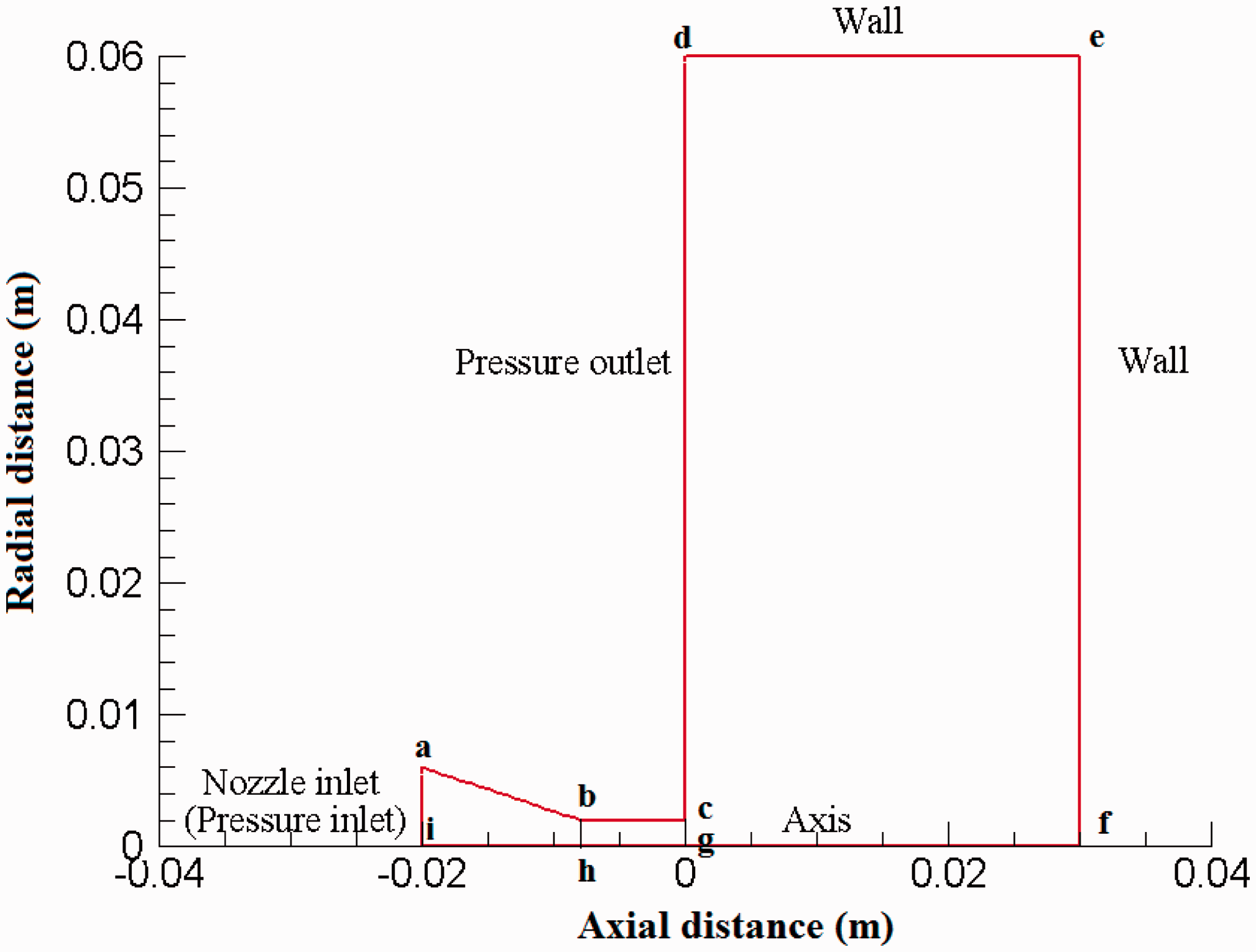
Model details
Governing equations of flow
Because the liquid nitrogen is compressible and sensitive to temperature and pressure, the equations of mass conservation, momentum and energy are needed to be solved during the simulation of liquid nitrogen jet. In addition, the k–ɛ model was selected to solve the turbulent flow which was generated by the strong shearing effect of jet. All of the equations were solved in the cylindrical polar coordinate system because the flow field geometry was axisymmetric. The detailed expression of the governing equations in cylindrical coordinates can be expressed as follows (He et al., 2016; Wang et al., 2015):
Mass equations

Momentum equations

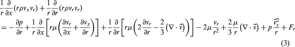
Energy equations

Property equations of nitrogen
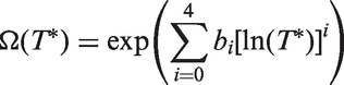
According to the governing equations in cylindrical polar coordinate system (equations (1)–(4)), a total of four properties of nitrogen were involved. They were isobaric heat capacity, density, thermal conductivity and viscosity. For the liquid nitrogen jet, the liquid nitrogen is stored in the low temperature and high pressure conditions. As a result, the flow cannot typically be modeled accurately using the ideal-gas assumption. With regard to such engineering problem, the real gas model should be employed. Thus, to ensure the accuracy of the simulation, the NIST real gas models were used to calculate the density, viscosity, isobaric heat capacity and thermal conductivity of nitrogen. As described in the Ansys Fluent user’s guide, the NIST real gas models use the National Institute of Standards and Technology (NIST) Thermodynamic and Transport Properties of Refrigerants and Refrigerant Mixtures Database Version 7.0 (REFPROP v7.0) to evaluate the properties of nitrogen. The property equations employed by the REFPROP v7.0 have high accuracy in evaluating the physical parameters of nitrogen. At the liquid state and high pressure (200 MPa), the uncertainties of density and isobaric heat capacity are within 1.5% and 2.0%, respectively. And the uncertainties in both viscosity and thermal conductivity are less than 2.0%. For the NIST real gas models, the density and isobaric heat capacity of nitrogen can be expressed by the Span et al. model (Span et al., 2000), which is explicit in the reduced Helmholtz energy. The Helmholtz energy is the function of two independent variables, density (ρ) and temperature (T) and the reduced Helmholtz energy is the function of reduced density (δ) and reduced temperature (τ), namely

The simplified equation for the ideal-gas component of reduced Helmholtz energy is:

The residual reduced Helmholtz energy is given by
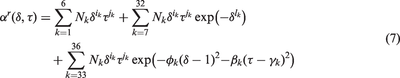
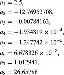
The coefficients of the equation (7) are all given in the reference of Span et al. (2000).
According to the Helmholtz energy theory, the expressions of density and isobaric heat are:


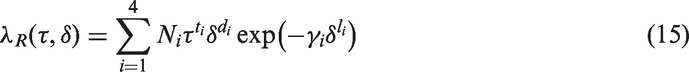
In addition, the pure fluid viscosity & thermal conductivity models of Lemmon and Jacobsen (2004) were used to evaluate the viscosity and thermal conductivity. The equation of viscosity is as follows:

The functional form for the viscosity of dilute gas is:

The residual fluid contribution to the viscosity is given by

The coefficients of this equation are also given in the reference (Lemmon and Jacobsen, 2004).
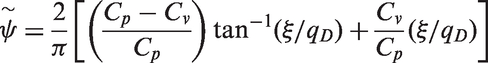
According to the models of Lemmon and Jacobsen, the thermal conductivity of nitrogen is the function of temperature and density:

The thermal conductivity of the dilute gas is expressed as follows:

The equation of residual part is:
The equation of the critical enhancement of thermal conductivity is

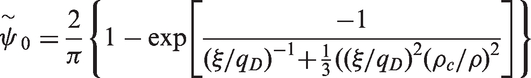
Because of limited space, the detailed calculation method of thermal conductivity can be referred to the relevant literature (Lemmon and Jacobsen, 2004).
Solution procedure
The liquid nitrogen jet is a kind of high velocity and compressible flow, the coupled solver in Fluent was adopted and the gravity was ignored (Wang, 2004). On the compute nodes, the nitrogen properties depended on the pressure and temperature. On the other hand, the change of the pressure and temperature affected the flow field in turn. To improve the calculation accuracy, the temperature, pressure, velocity, and nitrogen properties should be coupled solved. As expressed above, the NIST real gas models which use the REFPROP v7.0 database was employed to evaluate the physical properties of nitrogen. When the NIST real gas models are activated in the Fluent, the REFPROP v7.0 database will be dynamically loaded into the solver. Then, the physical properties including density, isobaric heat capacity, viscosity and thermal conductivity can be calculated according to the pressure and temperature of flow field. In each solving iteration loop, the mass conservation and momentum equations were solved in a coupled fashion at first, and then the energy and turbulent flow equations were solved (Guardo et al., 2006). In this case, the values of pressure, temperature and velocity on each node of the flow domain were obtained (Cheng et al., 2013). Before the convergence was checked, nitrogen properties on each compute node are updated based on the REFPROP v7.0 database.
During the jetting process, the high pressure liquid nitrogen flowed into the flow domain through the nozzle inlet (line ‘ai’), then was accelerated by the conical section of nozzle (quadrangle ‘abhi’), and was transformed into the liquid nitrogen jet at the nozzle outlet (line ‘cg’). Finally, the liquid nitrogen jet flowed out the flow domain after impacting the right wall (line ‘ef’). According to the flow principles, the nozzle outlet (line ‘ai’) was set as the inlet boundary, the flow field outlet (line ‘cd’) was set as the outlet boundary and other walls (lines ‘ab’, ‘bc’, ‘de’, ‘ef’) were set as non-slipping wall boundaries.
Flow field characteristics
To research the flow field characteristics of liquid nitrogen jet, the velocity and pressure contours of liquid nitrogen jets which were generated by 4 mm diameter and 6 mm diameter nozzles were simulated using the CFD model. During the jetting process of hydrajet fracturing, the fluid is injected from the tubing pipe, then is accelerated to a high speed by nozzle and flows back to the surface through the annulus. As the properties of nitrogen are very sensitive to the temperature and pressure, a chock pressure is usually applied on the wellhead to keep the flow in the annulus stable just like gas drilling. The applied chock pressure will lead to the downhole pressure increasing. In order to avoid the downhole pressure exceeding the fracture initiation pressure (FIP), the chock pressure should be controlled at a reasonable level.
Liquid nitrogen has been successfully implemented in wells with the depth less than 1000 m. The applicable depth is expected to be increased to 1500 m if the thermal insulation pipe is used (Xu, 2013). At such depth, the FIP of formation will be 25–30 MPa by assuming the 0.016–0.02 MPa/m FIP gradient. Thus, the downhole pressure during the jetting process must be less than this value. As a result, the 30 MPa was set as the maximum outlet pressure. For the high-speed jet, the confining pressure is generally characterized by the ambient pressure flow field. In this work, the confining pressure was defined as the pressure outside the nozzle (i.e. outlet pressure). In addition, the nozzle pressure drop (the difference between the nozzle inlet pressure and confining pressure) is also an important parameter. For hydrajet fracturing, the nozzle pressure is usually set as 20–30 MPa. In this paper, the nozzle pressure drop of 20 MPa was adopted. Correspondingly, the nozzle inlet pressure was set as 50 MPa. Finally, the inlet and outlet pressures of the flow domain were set as 50 MPa and 30 MPa, the standoff distance (distance between the nozzle outlet and target wall) was 30 mm and the inlet fluid temperature was 100 K. The simulation results are shown in Figures 2 to 4.
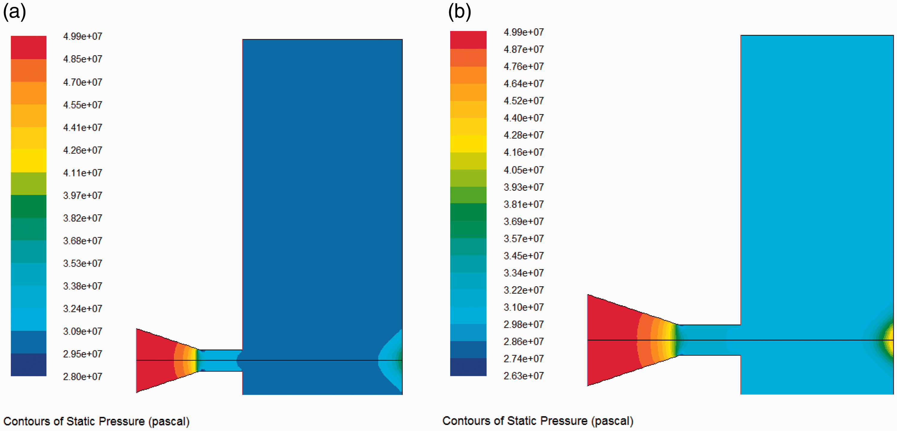
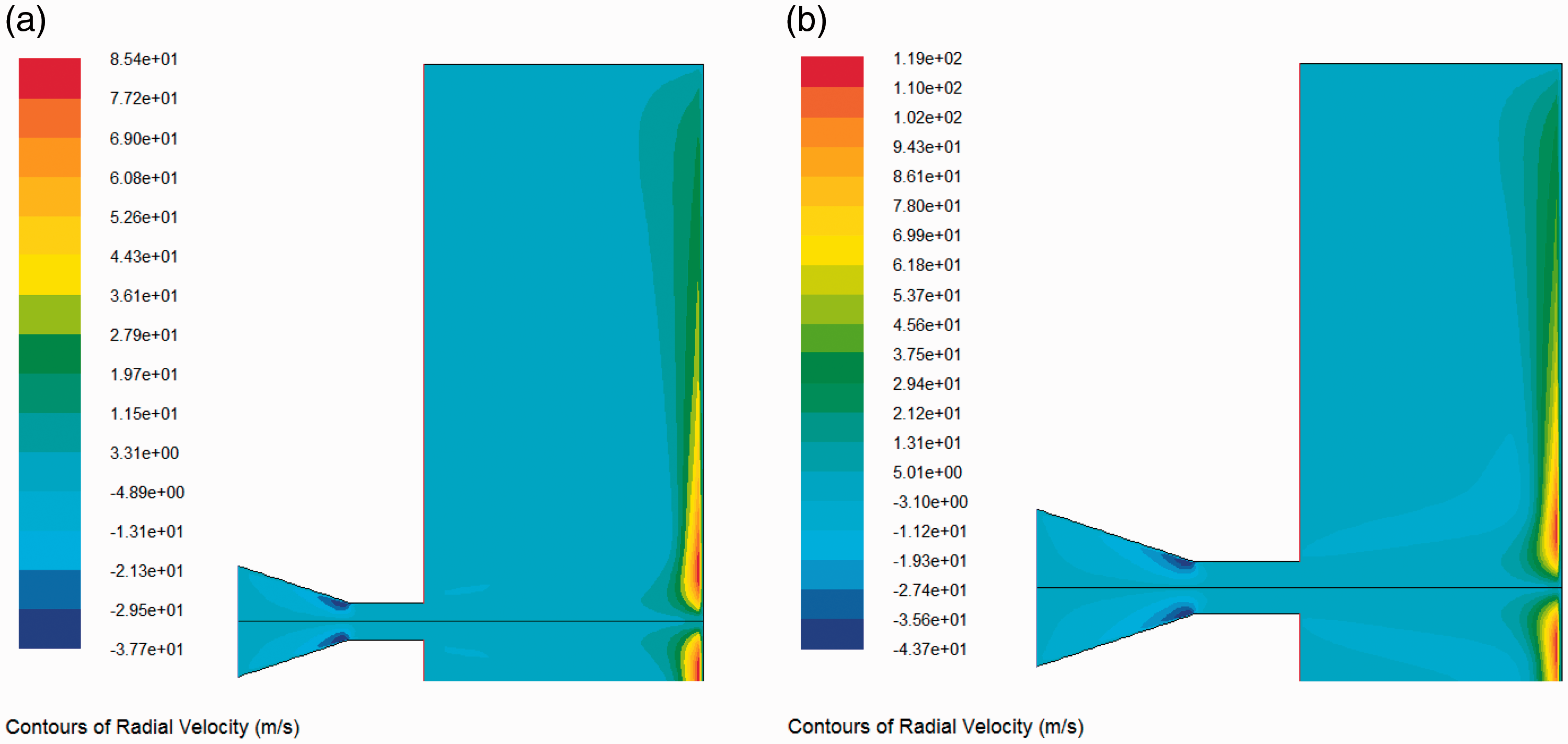
Velocity contours of liquid nitrogen jet. (a) 4 mm diameter nozzle and (b) 6 mm diameter nozzle. Pressure contours of liquid nitrogen jet. (a) 4 mm diameter nozzle and (b) 6 mm diameter nozzle. Radial velocity contours of liquid nitrogen jet. (a) 4 mm diameter nozzle and (b) 6 mm diameter nozzle.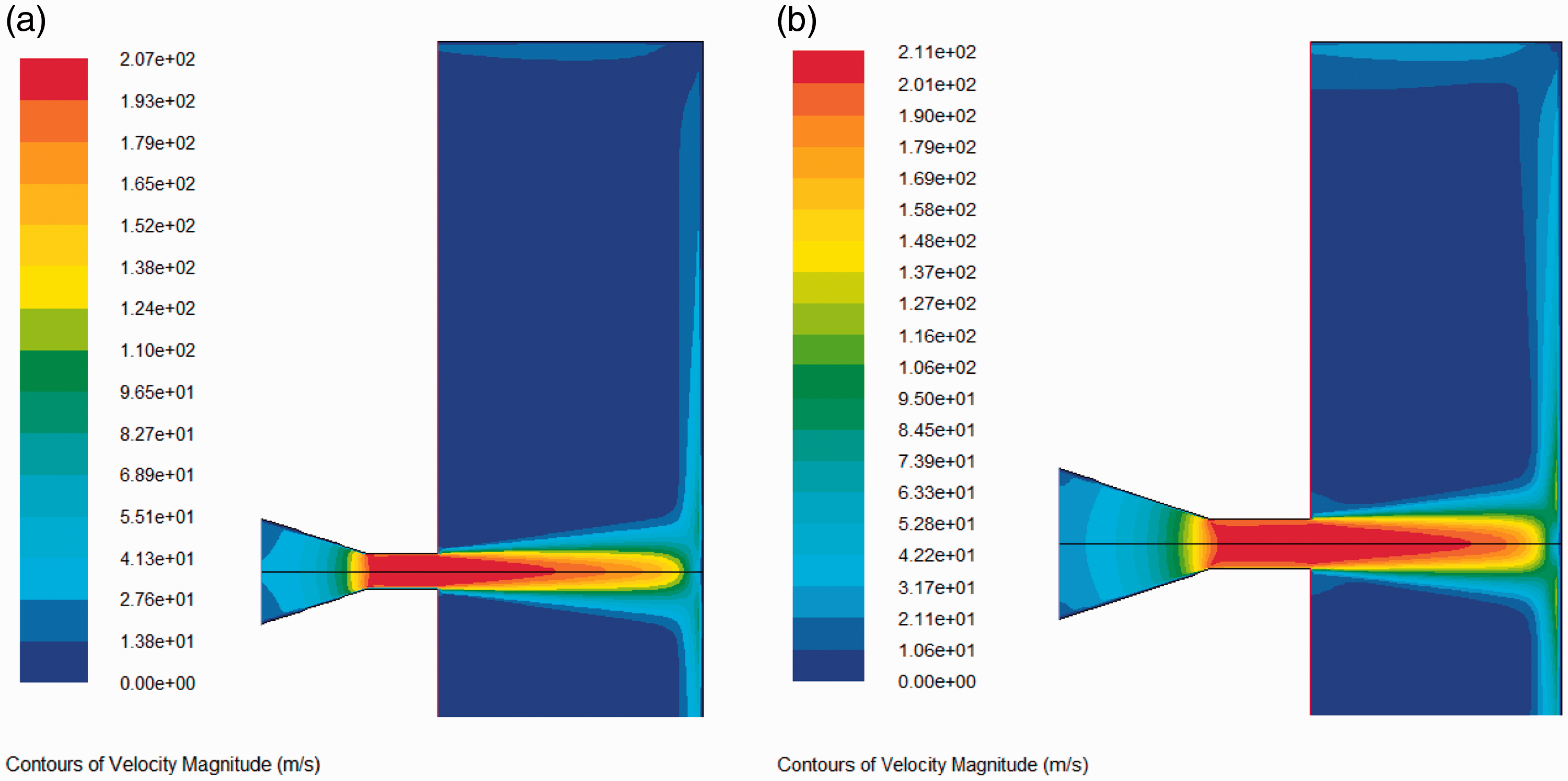
Velocity and pressure distributions
Velocity and pressure, as the key parameters of flow field, are also the important index to evaluate the impact capability of jet. Generally, the jet with a larger velocity has a greater impact capability and probably performs more efficiently in breaking rock. Figure 2 shows the velocity contours of liquid nitrogen jets respectively induced by the nozzles of 4 mm and 6 mm diameters. In the nozzle conical section, the jet velocity increased continually. The liquid nitrogen velocity reached the maximum value in the nozzle cylindrical section, thereby forming the high-speed liquid nitrogen jet. Thus, it can be seen that at the acceleration effect of nozzle, the high velocity jet which can be used to impact the target was generated.
As shown in Figure 2, the axial velocity of liquid nitrogen jet decreased sharply at the impact wall and then the jet diverted into an unconcentrated flow near the impact wall. In this work, the impact wall was defined as the wall which submerged the impact force of high-speed jet. At this wall, the axial velocity of jet decreases to zero and the stagnation pressure increases significantly. As shown in Figure 1, the right wall (line ‘ef’) was the impact wall. When the high velocity jet impacted the right wall, the partial kinetic energy would transform into pressure energy, resulting in the increasing of the stagnation pressure, namely generating the impact effect. On the impact wall surface, the pressure was largest on the jet center position and decreased along the radial direction. Take the 4 mm diameter nozzle for example; the wall pressure was 38.79 MPa on the jet center, was 33.01 MPa at the position 4 mm away the jet centerline and was equal to the confining pressure at the position 20 mm away from the jet centerline.
As shown in Figures 2 and 3, as the liquid nitrogen jet impacted the right wall, the impact effect and radial unconcentrated flow were generated. In the unconcentrated flow region, the liquid nitrogen flow attached the wall, which could induce the radial erosion effect. Figure 4 shows the radial velocity distributions of liquid nitrogen jet. Nearby the impact wall, the radial velocity increased due to the pressure difference along the radial direction. However, because of the viscous force caused by the wall, the radial velocity of liquid nitrogen jet began to decrease at a certain distance from the jet centerline. During the rock breaking with jet, the radial erosion effect can help to remove the cuttings and avoid the rock being broken repeatedly. Thus, the radial velocity is also a significant parameter to evaluate the impact capability of liquid nitrogen jet.
Impact effect of liquid nitrogen jet
According to the simulation results, three parameters can be used to evaluate the impact capability: axial velocity, radial velocity, and impact pressure. To analyze the impact capability of liquid nitrogen jet, the water jet field was also simulated at the same nozzle structure, nozzle pressure drop and confining pressure. As the water properties are hardly affected by the pressure and temperature, the physical parameters were set as follows. The density was 998.2 kg/m3, the viscosity was 10.03 × 10⁻⁴ Paċs, the thermal conductivity was 0.6 W/(mċK) and the isobaric heat capacity was 4.182 kJ/(kgċK).
Figures 5 and 6 respectively show the velocity and pressure distributions along the jet centerline and impact wall of liquid nitrogen and water jets, which were produced by the 4 mm diameter nozzle. As shown in Figure 5, the liquid nitrogen had a greater axial velocity than water jet. Nearby the nozzle outlet, the maximum axial velocity of liquid nitrogen jet was up to 206.73 m/s, presenting about 11.10% higher than water jet. With respect to the axial pressure, liquid nitrogen jet showed a similar changing rule to water jet. What’s more, the impact pressures of liquid nitrogen jet and water jet were also equivalent to each other. Figure 6 shows that even though the wall pressure difference of liquid nitrogen jet and water jet was very close, the radial velocity of liquid nitrogen was obviously greater than water jet. At the jet center point, the radial velocity of liquid nitrogen jet indicated about 13.51% greater than water jet. The velocity and pressure distributions further showed that a more excellent impact effect was expected to be produced with the liquid nitrogen jet instead of water jet.
Axial velocity and pressure distributions of liquid nitrogen and water jets along axial direction. Radial velocity and pressure distributions of liquid nitrogen and water jets along radial direction.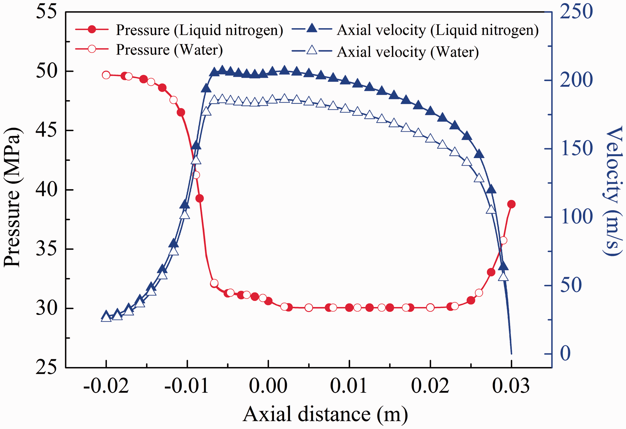
Parametric sensitivity analysis on impact capability of liquid nitrogen jet
As mentioned above, the impact capability is very important for rock breaking with liquid nitrogen jet. Generally, the greater the impact capacity is, the more excellent the rock breaking capacity of jet will be. Thus, a parametric sensitivity analysis was conducted to assess the effect of the relevant parameters on the impact capacity of liquid nitrogen jet. In this section, the maximum axial velocity (near the nozzle outlet), the maximum radial velocity (near the impact wall) and the maximum impact pressure (on the impact wall surface) were selected as the jet impact parameters. In this paper, the impact pressure was defined as the difference between the wall pressure and confining pressure.
Nozzle pressure drop
Nozzle pressure drop, namely, the difference between the nozzle inlet pressure and confining pressure is mainly related to the nozzle structure and flow rate. It can be used to access the value of jet kinetic energy. As shown in Figure 7, the maximum axial velocity, maximum radial velocity and maximum impact pressure of liquid nitrogen jet increased with the growth of nozzle pressure drop. For instance, they increased by 72.84%, 78.71% and 219.19% respectively as the nozzle pressure drop increased from 10 MPa to 30 MPa. It was because that the kinetic energy of jet was positively related to nozzle pressure drop. The larger nozzle pressure drop can make the jet have greater kinetic energy. In this case, the liquid nitrogen jet could present higher axial velocity after it flowed through the nozzle. Moreover, the kinetic energy could be converted into pressure energy and kinetic energy of unconcentrated flow when the liquid nitrogen jet impacted the target wall.
Effect of nozzle pressure drop on the impact capability of liquid nitrogen jet.
Nozzle diameter
To study the effect of nozzle diameter on the impact capability, the flow fields of liquid nitrogen jet generated by the nozzles with different diameters were simulated. Figure 8 depicts the relationship of impact parameters and nozzle diameter. Both the maximum radial velocity and the impact pressure of liquid nitrogen jet increased considerably with the increasing of nozzle diameter while the axial velocity was slightly related to the nozzle diameter. For example, the maximum impact pressure and maximum radial velocity of liquid nitrogen jet increased by 474.75% and 203.53% as the nozzle diameter increased from 2 mm to 8 mm. However, given the same conditions, the maximum axial velocity only presented a 6.62% increase. It was because that the growth of nozzle diameter mainly widened the jet flow area, but hardly affected the jet kinetic energy per area. Thus, the axial velocity of liquid nitrogen jet increased slightly with the growth of nozzle diameter. But the liquid nitrogen jet generated by a larger nozzle had greater total kinetic energy; more kinetic energy would be transformed into the pressure energy and the kinetic energy of unconcentrated flow. Therefore, a larger impact pressure and higher radial velocity can be formed with a larger nozzle.
Effect of nozzle diameter on the impact capability of liquid nitrogen jet.
Confining pressure
During the liquid nitrogen jetting process, the confining pressure usually indicates the flow pressure outside the nozzle. In petroleum engineering, the jet mainly works under the confining pressure condition. With the growth of well depth, the confining pressure increases continuously. As shown in Figure 9, the maximum axial velocity, maximum radial velocity and maximum impact pressure hardly changed with the variation of the confining pressure. It showed that the impact capability of liquid nitrogen jet wasn’t weakened with the increasing of confining pressure. This was because that the growth of confining pressure improved the pressure level of the whole flow field, but had little influence on the kinetic energy of liquid nitrogen jet. As a result, the impact capability of liquid nitrogen jet did not change remarkably with the variation of confining pressure.
Effect of confining pressure on impact capability of liquid nitrogen jet.
Standoff distance
Standoff distance is the distance between the nozzle outlet and target wall, which is an important parameter to access the efficient impact scope of jet. For field application, the standoff distance cannot be ensured constant due to the restrictions of wellbore and jet tool. To uncover the effect of standoff distance on the impact capability of liquid nitrogen jet, the jet flow fields given the standoff distances from 10 mm to 50 mm were simulated. As shown in Figure 10, the axial velocity was hardly affected by the standoff distance, but the maximum radial velocity and maximum impact pressure decreased with the growth of standoff distance. This was because that with the increasing of standoff distance, the loss of jet kinetic energy increased due to the viscous action of surrounding fluid. Thus, the kinetic energy of liquid nitrogen would be weakened as the liquid nitrogen jet impacted the target wall with a great standoff distance. Consequently, the pressure energy and the kinetic energy of unconcentrated flow which were transformed by jet kinetic energy decreased correspondingly.
Effect of standoff distance on impact capability of liquid nitrogen jet.
Fluid temperature
To investigate the effect of the fluid temperature on the impact capability of liquid nitrogen jet, the jet flow fields given different temperatures were simulated. As shown in Figure 11, the maximum axial velocity, maximum radial velocity and maximum impact pressure all presented a small increase with the growth of fluid temperature. For instance, as the fluid temperature increased from 80 K to 120 K, the maximum axial velocity, maximum impact pressure and maximum radial velocity increased by 14.04%, 8.49% and 12.37%, respectively. The critical temperature of nitrogen was 126.192 K. When the fluid temperature exceeds this value, the nitrogen will exist in gas state. Thus, the simulation results indicated that even though the nitrogen temperature was near its critical point, the increase in the temperature would not weaken the impact capability of liquid nitrogen jet.
Effect of fluid temperature on impact capability of liquid nitrogen jet.
Conclusions
Given the same nozzle structure and nozzle pressure drop, the axial velocity and radial velocity of liquid nitrogen jet were higher than water jet. Take the nozzle of 4 mm diameter for example; the maximum axial velocity and maximum radial velocity of liquid nitrogen were 11.10% and 13.51% greater than water jet at the 20 MPa nozzle pressure drop. The impact capability of liquid nitrogen jet increased with the growth of nozzle pressure drop, nozzle diameter and fluid temperature. The axial velocity, radial velocity and impact pressure of liquid nitrogen jet were enhanced obviously with the growth of nozzle pressure drop. Using the larger diameter nozzle was beneficial to improving the impact pressure and radial velocity of liquid nitrogen jet. With the growth of standoff distance, the axial velocity of liquid nitrogen hardly changed, but the impact pressure and radial velocity decreased continuously. In this case, the impact capacity of liquid nitrogen jet was weakened. The confining pressure hardly affected the axial velocity, radial velocity and impact pressure, which could broaden the engineering applicability of liquid nitrogen jet.
Footnotes
Acknowledgements
We would like to acknowledge Mr. Xiaoguang Wu from China University of petroleum, for his critical assistance in the work, which significantly improved the quality of the manuscript.
Declaration of conflicting interests
The author(s) declared no potential conflicts of interest with respect to the research, authorship, and/or publication of this article.
Funding
The author(s) disclosed receipt of the following financial support for the research, authorship, and/or publication of this article: The authors would like to thank the financial support from the Natural Science Foundation of Jiangsu Province (No. BK20160252), the National Natural Science Foundation of China (Nos. 51604263 and 51574219), the State Key Research Development Program of China (No. 2016YFC0600705), the Project funded by China Postdoctoral Science Foundation (No. 2016M590523), and the Priority Academic Program Development of Jiangsu Higher Education Institutions (PAPD2014).