
Abstract
In order to decrease the fiber diameter and reduce the energy consumption in the melt-blowing process, a new slot die with internal stabilizers was designed. Using computational fluid dynamics technology, the new slot die was investigated. In the numerical simulation, the calculation data were validated with the laboratory measurement data. This work shows that the new slot die could increase the average velocity on the centerline of the air-flow field by 6.9%, compared with the common slot die. Simultaneously, the new slot die could decrease the back-flow velocity and the rate of temperature decay in the region close to the die head. The new slot die could reduce the peak value of the turbulent kinetic energy and make the fiber movements more gradual. With the one-dimensional drawing model, it proves that the new slot die has more edge on the decrease of fiber diameter than the common slot die.
Introduction
Melt-blown technology is a rapidly developing and promising non-woven process with its high production speed and high production efficiency. The resulting ultrafine fibers will be deposited on the collecting device and become a non-woven material. The finest melt-blown fibers are close to the nanoscale [1] and have an average diameter of microns or submicron. Compared with most common fibers, melt-blown fibers have the advantages of small diameter and large specific surface area, and can be used as advanced filter materials, heat retaining materials and oil absorbing materials [2,3].
The die head is one of the core components in a melt-blown production facility. Figure 1 shows a common slot die. The two high-speed and high-temperature jets produced by the slot die, which can stretch the melt polymer into ultrafine fibers. The flow field below the airflow die not only determines the diameter of the final melt-blown fiber, but also has a large effect on the fiber strength. The research of the flow field from the melt-blown die is the basis of the whole fiber drawing process. Therefore, researchers have conducted relevant experimental studies and numerical simulations around the die head and its airflow field. In experimental research, Harpham and Shambaugh [4,5] using a pitot tube measured the air-flow field at low speed under the single-orifice slot die (see Figure 1). Xie et al. [6,7] obtained the turbulent air flow field under the common slot die with the aid of a hot wire anemometer. In terms of numerical calculations, Krutka and Shambaugh [8] firstly used computational fluid dynamics (CFD) techniques to simulate the low velocity and isothermal flow-field under the common slot die in 2002. They obtained the velocity distribution in the incompressible state, and examined the influence of the geometric parameters of the die on the flow field. Krutka et al. [9,10] employed Fluent software to calculate the airflow field under the slot die and investigated the effects of die noses on the flow field. Chen et al. [11] used CFD software to carry out numerical research on a common slot die and analyzed the influence of geometric parameters on flow field. Sun et al. [12] with CFD technology optimized the airflow field under the common melt-blown die. Xin and Wang examined the effect of the angle of dual slots on an air flow field via numerical simulation [13]. Hao et al. [14] conducted a numerical study on the coupled flow field of the fiber and the air flow and investigated the influence of processing parameters on the flow field.
The common slot die. (a) Cross-sectional view; (b) vertical view.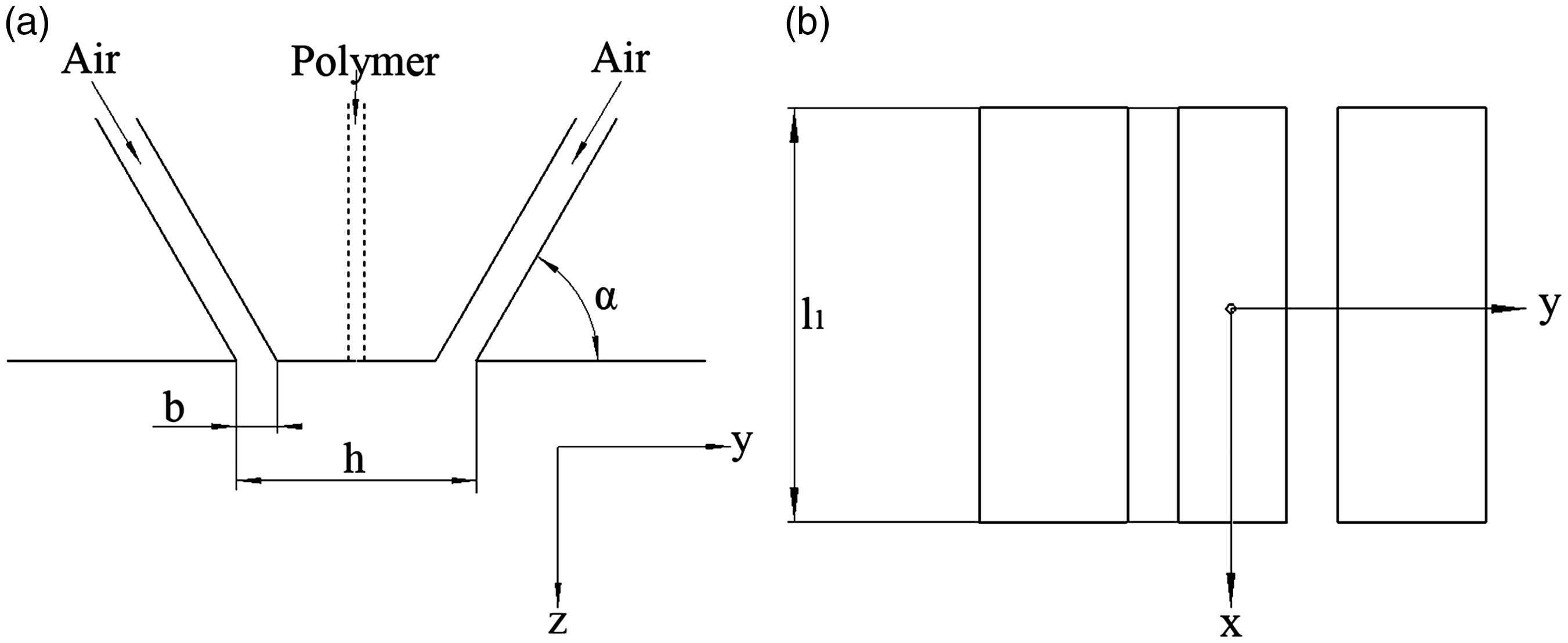
The above researchers were all working on the common slot die. The common slot die is the most widely used, because it can produce a theoretically infinitely wide product and adapts to the future direction of widening. However, there are some unfavorable factors in the common die that restrict the further refinement of the fiber and cause a large energy consumption [8–10,15–17]. Two separate jets spread around and cause kinetic energy loss. In addition, the temperature on the center of the flow field drops too fast [5,10,12], which is not conducive to the drafting of the fiber. On the one hand, if the production energy consumption can be reduced, the production costs can be effectively saved and the market competitiveness of the melt-blown product can be improved. On the other hand, thinner melt-blown fibers can greatly improve the properties of melt-blown products. Therefore, it is of great practical significance to reduce the energy consumption and the fiber diameter in the melt-blowing process.
In this paper, in order to further attenuate the melt-blown fibers and cut down the production energy consumption, a new type of melt-blown slot-die head was designed. Meanwhile, with the help of CFD technology the numerical studies on the air-flow field from the new slot die was conducted.
New melt-blowing slot-die
Figure 1 gives a cross section view of a common slot die. The width b of air slot was defined as 0.65 mm, the distance h of the outer wall of the two gas-slots was defined as 3.32 mm, and the slot angle α makes with the die face was 60°. In this research, the redesigned new die in Figure 2 was based on the common slot die whose structures are similar with each other. Thus, the three parameters mentioned above were all same. Figure 2 shows a schematic of a newly designed melt-blown die head with internal stabilizers on the inner side of the two gas slots. The internal stabilizers were designed to reduce the kinetic energy loss of the jet and reduce energy consumption. The height Ih of the internal stabilizers was 1 mm, and the angle between the internal stabilizer and the die face was 60°. The length l2 of the internal stabilizers was equal to the length l1 of the gas slot (see Figures 1 and 2).
The new slot die. (a) Cross-sectional view; (b) vertical view.
Numerical calculation
Calculation domain and grid generation
In this paper, two-dimensional numerical calculations on the common slot die and the new slot die were performed. The reason is that the three-dimensional flow field from the slot die has the characteristics of two-dimensional flow field [4]. What's more, the three-dimensional numerical calculation of the melt-blowing die head requires a large amount of time due to its large calculation domain and many meshes. In actual use, the two-dimensional calculations of the slot die heads can save a lot of time. In this work, FLUENT 6.3.26 was used for numerical calculations of the common slot die and the new slot die. It should be noted that in the numerical simulation study in this section, the existence of melt-blown fibers are ignored by default.
The calculation domain, the boundary conditions and the grid generation of this new slot die were all as same as that of the common slot die. The two dimensional numerical domain and grid generation for the common slot die could be described in Figure 3 based on the previous researches [8]. In geometry, the projection length of the gas slot region on the z axis was 5 mm and the width AB of the slot region was 0.65 mm. To be more specific, the point O was the origin of coordinates, the y-axis was parallel with the line OE and the z-axis was parallel with the line OC. The length of OE and OC were 30 mm and 100 mm respectively. As a result, the closed 100 × 30 mm2 rectangular and the gas slot area were the numerical domain. In the two dimensional numerical simulation, the line OC was the symmetric boundary condition because the common slot die was symmetric about this line, which could reduce the time consumption of the simulation process significantly.
Computational domain of the common slot die.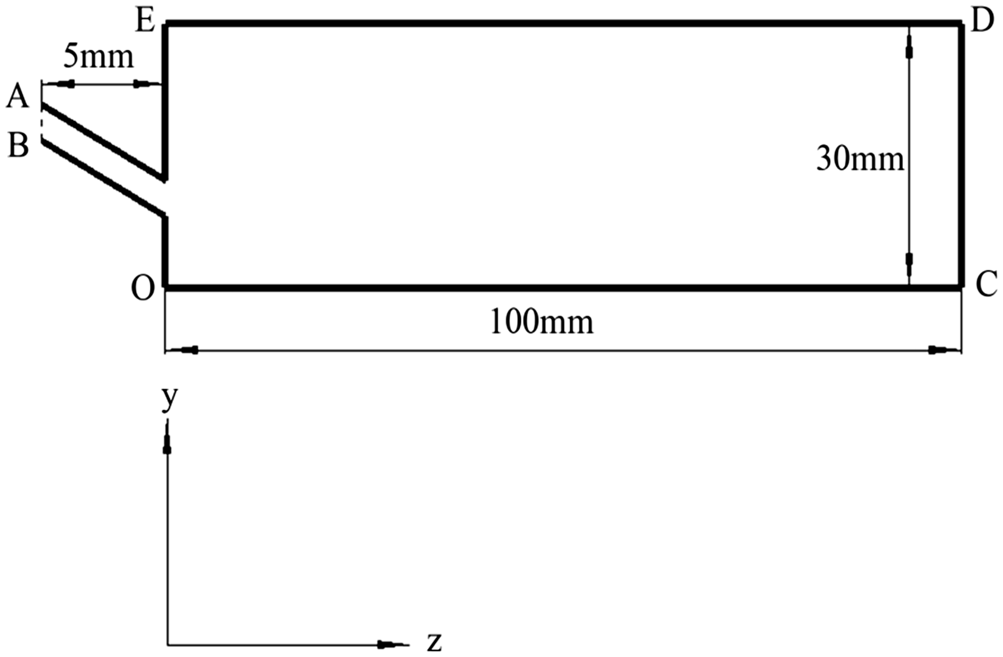
In the computational domain, the quadrangular structured mesh was adopted. The minimum scale of grid was 0.05 mm in the core region while the maximum scale was 0.1 mm in the other region. As a result, in the computational domain for the common die, the total number of grid was 354492, which could guarantee calculation accuracy [8].
Turbulence model
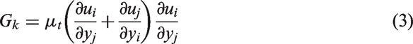
The standard k−ɛ model was used to simulate the turbulent flow field of the new slot die and the common slot die in this work. Compared to the Reynolds stress model, the standard k−ɛ model can accurately calculate the turbulent core area in the simulation is more economical, because it has shorter calculation time.
The time-average form of the standard k−ɛ model is


The research team used the hot wire anemometer to measure the airflow field of a common slot die. The one-dimensional probe used in the experiment was Dantec Dynamic 55P11 and mounted on a three-dimensional traverse device. One-dimensional probe collects data from the flow field at intervals of 0.01 mm. In Figure 4, the experimental conditions were that the inlet pressure was 1.3 atm and the jet initial temperature was 403.15 K. It proves that experimental data are consistent with the simulated data and the standard k−ɛ model can accurately calculate the high-speed flow-field from the common slot die.
Comparison of simulated data and experimental data.
Boundary condition
AB was the pressure inlet of calculation domain and the temperature at the inlet was 480 K. The ideal gas was introduced in this the pressure of 1.05 atm. The hydraulic diameter equals to the width of inlet and the turbulence intensity was 10%. DE and CD were outlets whose pressure and temperature equal to the atmospheric environment. The length scale of the two lines was 10 mm. OC was set to symmetric boundary condition. In the standard k−ɛ model,
Numeral calculation results and discussion
The centerline velocity of the two slot-dies
Bansal and Shambaugh [18] established an experimental system for online measurement of melt-blown fiber diameter and fiber temperature. They found that more than 96% of the fiber stretch occurred within 0.015 m from the spinneret outlet of the melt-blowing die-head. In addition, the melt-blowing fibers move mainly along the centerline of the flow field. Therefore, in this work, the velocity temperature and turbulent kinetic energy and so on in the centerline of the air-flow field, which is associated with fiber drawing, are of concern.
Figure 5 presents the centerline velocity for the two dies in different z position. It is obvious that the velocities within a very narrow distance near the common slot die is less than 0 m/s, which is contrary to the direction of fiber drawing and is easy to push the polymer melt back into the orifice. Compared with that of common slot die, the peak and breadth of the reverse speed are smaller. For the new slot die, it means that it is more conducive to the smooth progress of the fiber drawing. At the same time, the maximum of the centerline velocities for the new slot die are higher than that of the common die.
Velocity comparison of the two slot-dies.
It can be seen in Figure 6(a) that a recirculation zone [8,19], where there is full of separation vortex, is close to the common slot die. This condition is a typical kinetic energy loss. Figure 6(b) shows that the internal stabilizers reduce the area of the recirculation zone and suppress the generation of separation vortices, which is helpful to diminish reverse speed value. Moreover, the internal stabilizers can prevent the two high-speed jets from spreading to the inside and lower the kinetic energy loss of the two jets. So the new slot die has greater speed values in most areas on the centerline of the flow field, compared to the common slot die.
The velocity vector in the recirculation zone for the two slot-dies. (a) The common slot die; (b) the new slot die.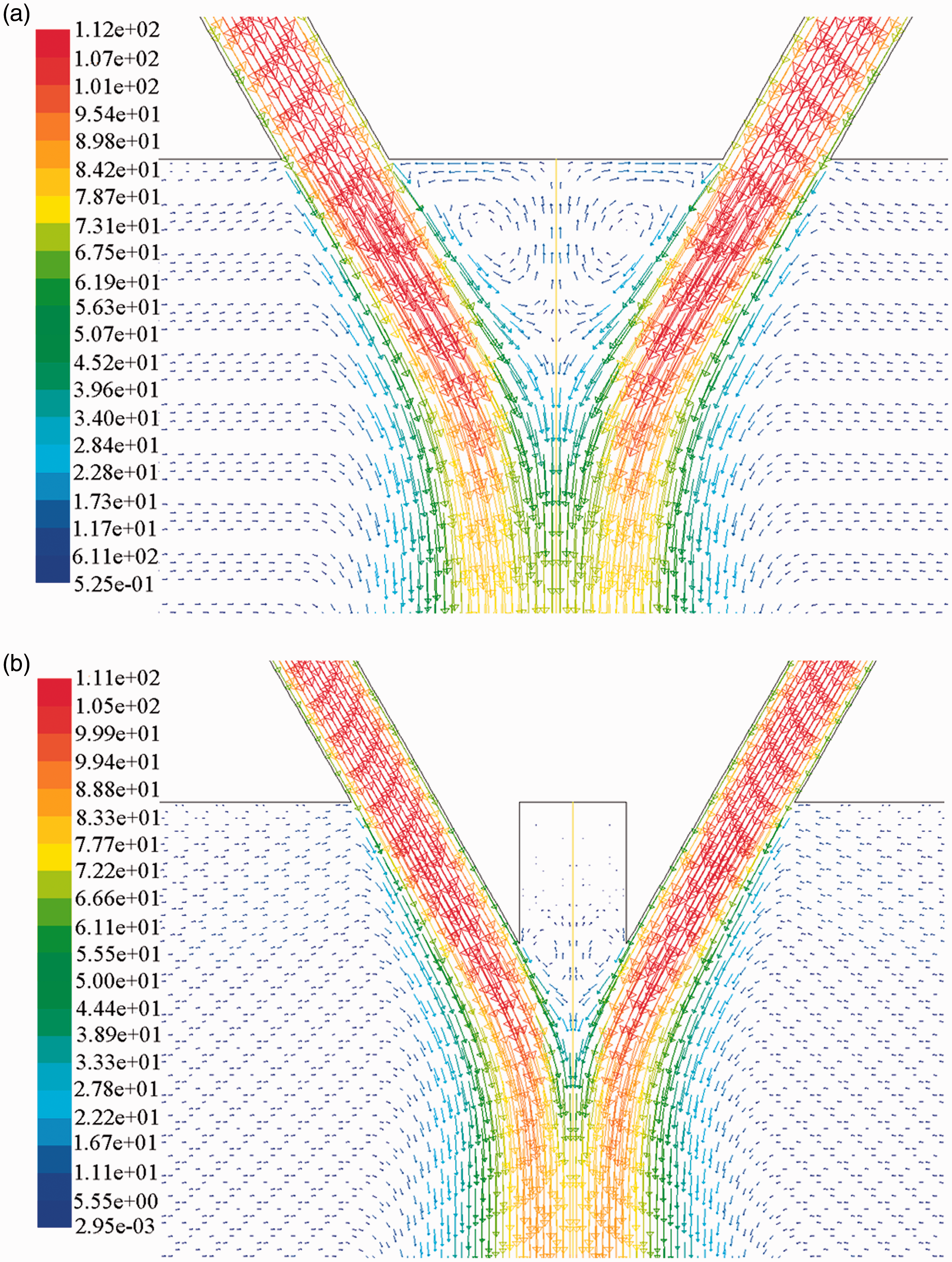
The average speed value along the centerline for the slot die is 53.0776 m/s, and the average speed value along the centerline for the new die is 56.7413 m/s, correspondingly, which increased by 6.9%. The drafting force for the melt-blowing fiber is proportional to the square of the speed difference between the air flow rate and the fiber speed. For the melt-blowing process, the higher the centerline velocity is, the thinner the diameter of fiber is when other parameters are maintained at a constant value. Therefore, it is easier to produce the micro fiber and reduce the diameter of fiber. What is more, the new slot die can save more gas consumption than the common die when preparing fibers with the same fineness.
The centerline static pressure of the two slot-dies
Figure 7 gives two curves about the static pressure along the centerline under the dies. The static pressure values show the same pattern, for the two slot dies. The pressures of the two slot dies first increases, then decreases, finally tend to a gentle straight line.
Static pressure comparison of the two slot-dies.
Figure 7 reveals that the static pressure peak of the new slot die is higher and appears later than that of the common slot die. This is due to the presence of internal stabilizers that cause the two jets to meet later, as can be seen from Figure 6(b). The reduction of the kinetic energy loss leads to an increase in pressure peak for the new slot die. For the two slot dies, the pressure peaks are near the die face and their positions are closer than that of that of the velocity peaks.
The turbulence-kinetic energy in the centerline for the two slot-dies
The turbulence kinetic energy curves of the two slot dies in the centerline are showed in Figure 8. Based on the curve, it is obvious that the turbulent kinetic energies for the two dies increases sharply to peaks in a very small area and rapidly lower to a certain values, then begin to slowly drop. Comparing Figure 5, the peak positions of the turbulent kinetic energy for the two slot dies appear earlier than that of the velocity. As can be seen from Figure 8, the maximum value of the turbulent kinetic energy for the new slot die is greatly reduced than that of the common slot die. In most of the centerline, the turbulence kinetic energy of the new slot die is lower than that of the common one. The smaller the turbulent energy is, the more gentle the airflow is and the smoother the fiber drawing process is. If a new slot die is used, the polymer melt can be prevented from sticking to the die surface and the fiber breakage rate can be reduced, which is more meaningful to the melt-blown fiber drawing than the common slot die.
Turbulent kinetic energy comparison of the two slot-dies.
The internal stabilizers greatly reduce the reverse speed of the recirculation zone, resulting in a smoother flow of airflow in the vicinity of the slot die. Therefore, the turbulence energy peak value of the new slot die is smaller than that of the common die.
The centerline static temperature of the two slot-dies
Figure 9 gives the static temperature change between z = 0 m to z = 0.015 m. On one hand, it can be seen that the static temperature values of the two kinds of slot dies gradually decrease and show the same trend. On other hand, almost throughout the flow field, the static temperature of the new slot die is higher than that of the common slot die. As the distance to the die face is reduced, the temperature difference on the centerline of the two slot-dies increases.
Static temperature comparison of the two slot-dies.
In the flow field of the slot die, the thermal energy is lost not only by heat conduction and heat radiation, but also mainly by convective heat transfer. This is because convective heat transfer is the main way of heat transfer in fluids (gas, liquid) and can take away a lot of heat energy. Figures 5 and 6 show that the reverse velocity of the common die in the recirculation zone is larger, and the convective heat transfer effect is more significant than that of the new slot die. Therefore, the new slot die has a greater temperature advantage near the die surface than the common slot die.
In the melt-blowing process, the static temperature in centerline is the key parameter for the quality of fiber elongation [18]. The higher the temperature in the air flow field is, the smaller the fiber diameter is. The new slot die present a greater temperature advantage and is more conducive to fiber refinement than the common one. Getting the same fiber diameter, the new slot die can save more gas consumption and heat energy consumption than the common die.
Fiber diameter prediction
Combining one-dimensional fiber stretching model [20] which was solved by using a fourth order Runge–Kutta method and numerical calculation of flow fields below the common slot die and the new die, the diameter of the melt-blown fiber could be obtained. For the two slot dies, the initial air pressure was 1.35 atm, the melt polymer temperature was 260℃, and the hot air temperature was 330℃.
Figure 10 shows a fiber diameter variation curve along the flow field centerline for the two kinds of slot dies. Obviously, the new die has a faster drafting rate and allows for finer melt-blown fibers under the same conditions. This is due to the higher airflow drafting speed and higher airflow temperature of the flow field from the new die.
The predicted diameters for the common die and the new die.
Conclusion
In this research, based on the numerical simulation of the common slot die and the new slot die, a list of conclusions can be obtained. The internal stabilizers of the new slot die can lessen the area of the recirculation zone and reduce the spread of the jet. Therefore, for the new slot die, the reverse speed peak is smaller and the average speed and speed peak on the centerline is higher than that of the common slot one. When the inlet pressure of the air jets is 1.05 atm and the initial temperature is 480 K, the average speed of the new die on the centerline can be increased by 6.9%. The new melt-blown die has larger temperature and smaller peaks of the turbulent kinetic energy than the common one. Because the internal stabilizers affect the intersection of the two jets and diminish the radial diffusion to some extent, the pressure peak of the new slot die delays and increases. With the aid of the one-dimensional tensile model, it proves that the new slot die can produce finer fibers than the common one.
Footnotes
Declaration of conflicting interests
The author(s) declared no potential conflicts of interest with respect to the research, authorship, and/or publication of this article.
Funding
The author(s) disclosed receipt of the following financial support for the research, authorship, and/or publication of this article: This work was financially supported by the College Innovation Project (no. 201701D31111186), Scientific and Technological Innovation Programs of Higher Education Institution in Shanxi (no. 2019L0992) and the National Natural Science Foundation of China (grant no. 51776034).