
Abstract
To investigate the effect of pore pressure distribution on fracture behavior of rock in gas fracturing, nitrogen fracturing experiments on the sandstone are performed under different gas filtration conditions. Results indicate that the breakdown pressure of the sandstone reduces with the decreasing amount of gas filtration. In no gas filtration case, the breakdown pressure value of the sample decreases by 69.98 and 45.6% in comparison to no gas invasion case and gas filtration case, respectively. The failure pattern of the sandstone sample is determined by borehole pressure and pore pressure, and it is mainly controlled by borehole pressure at high injection rate and controlled by pore pressure at low injection rate. In addition, pore pressure can promote microcracks initiation and high pore pressure distribution contributes to generating complex multifractures network. Furthermore, in order to popularize the experimental results to the field application, a method of special graded particles is proposed to temporarily plug induced and natural fractures during fracturing process and then prop these fractures after fracturing. The method is expected to improve fracturing efficiency and increase production of oil and gas in practical application.
Keywords
Introduction
Currently, hydraulic fracturing has been widely used to enhance production of oil and gas reservoirs, especially unconventional gas reservoirs (Arthur et al., 2008; Jang and Lee, 2015; Saldungaray and Palisch, 2012). Most unconventional gas reservoirs have extremely low permeability, which greatly prohibits efficient extraction from reservoir rocks to production wells and the economic viability of developing unconventional gas depends on effective stimulation of reservoirs (Bennour et al., 2015; Jia et al., 2015; Li et al., 2015). However, many problems can be caused with the application of hydraulic fracturing in the field. First, large volumes of water injection have led to water use issues (Brantley et al., 2014; Vengosh et al., 2014). A typical shale gas well injects between 2 and 4 million gallons of water into a deep shale reservoir (Scanlon et al., 2014). This undoubtedly intensifies the water shortage in arid areas. Second, vast amounts of water stay in the formations near the fractures after hydraulic fracturing, resulting in the water saturation of the rock, clay swelling, and water locking which can decrease the relative permeability of oil/gas and block the seepage channels (Anderson et al., 2010; Holditch, 1978; Huang et al., 2015; Lai et al., 2005; Ma et al., 2015b). In addition, hydraulic fracturing has also been associated with potential freshwater contamination during the injection/production phases as well as with water disposal because that the large amounts of the various chemical components are used in the fracturing fluids (Gassiat et al., 2013; Holtsclaw et al., 2011; Small et al., 2014). Therefore, to solve the problems associated with hydraulic fracturing and its negative effects on the environment, the idea of nonaqueous fracturing (including CO2 fracturing, N2 fracturing, and other gas fracturing methods) has grown over the last several years as an efficient and environmentally friendly way of performing the hydraulic fracturing (Hou et al., 2016a, 2016b; Middleton et al., 2015). Using nitrogen gas for fracturing has attracted progressively greater attention and can fundamentally solve the environmental problems relative to water use and pollution, and prevent reservoir damage (Alpern et al., 2012; Palmer and Sito, 2013; Rogala et al., 2013).
Rock has infinite number of small pores, and the shape and the interconnectivity of pores bring special feature in mechanical behavior of rocks (Ito, 2008). When fluids are injected into the borehole, fluid penetrates through interconnected pores into rock from the borehole wall resulting in changes in pore pressure. The fracturing behavior of rock is influenced by both pore pressure magnitude on a local scale around the microcrack tip and distribution of pore pressure gradients on a global scale (Bruno and Nakagawa, 1991). Many researchers have investigated the effect of pore pressure on the fracturing behavior of rock based on hydraulic fracturing. Bruno and Nakagawa (1991) studied the effect of pore pressure on the tensile fracture initiation and propagation direction by theoretical analysis and hydraulic fracturing experiments and the results indicated that the strain energy release rate is the maximum for tensile fracture propagation toward regions of higher local pore pressure. Ito (2008) proposed a model which defined the relationship between breakdown pressure and tectonic stresses based upon the point stress criterion and discussed in detail how the fluid permeation perturbs the stress field around the borehole. Li et al. (2015) and Ma et al. (2015a) numerically investigated how pore pressure distribution can affect fracture propagation in brittle rock materials and discovered that the pore pressure magnitude has a direct influence on the fracturing path of tensile fracture and strength behavior in rock. Using nitrogen gas as fracturing liquid has been studied for a long time, but related reports are rare in this area. However, as we know, there are many different features between water and nitrogen gas, especially viscosity of fluid which can result that nitrogen gas leakage is more serious than water in reservoirs.
In this paper, at first the nitrogen gas fracturing experiment system was built in the laboratory. Then three seal methods (i.e. no gas invasion, gas filtration, and no gas filtration) were designed in nitrogen gas fracturing to denote different pore pressure distribution. The gas injection rate was considered as a possible way to change the magnitude of pore pressure based on previous researches in hydraulic fracturing (Ito, 2008; Ito and Hayashi, 1991). Effects of pore pressure distribution on the breakdown pressure, failure mode, and microstructure of the sandstone sample were studied in nitrogen fracturing. Based on the results of the completed experiments, an optimal scheme that can improve fracturing efficiency was proposed in nitrogen fracturing.
Experimental materials and procedure
Sample preparation
The sandstone samples were acquired from a mine in Xuzhou City, Jiangsu Province, China. This sandstone is the red sandstone with relatively homogeneous structure of the fine grain. The component of the sandstone was tested by the X-ray diffraction. The sandstone consists of quartz, feldspar, calcite, and other amorphous minerals (Figure 1(a)). The pore structure and microstructure of rock are main seepage passageways and seriously affect the permeability of rock (Wang et al., 2015). Therefore, the pore size and pore size distribution, and microstructure of the sandstone were analyzed by the mercury intrusion porosimeter (MIP) and scanning electron microscope (SEM), respectively; the results are shown in Figure 1(b) and (c). Figure 1(b) indicates that the pore diameters of the sandstone widely distribute in the range 10–100,000 nm, only a few in the range 1–10 nm. The porosity of the sandstone is 7.83% obtained by the MIP test. Based on the SEM image of the sandstone, the grains of the sandstone are loosely arranged and the vast pore structures exist in the intergrains.
Characters of the sandstone. (a) Component, (b) pore diameter distribution, and (c) microstructure.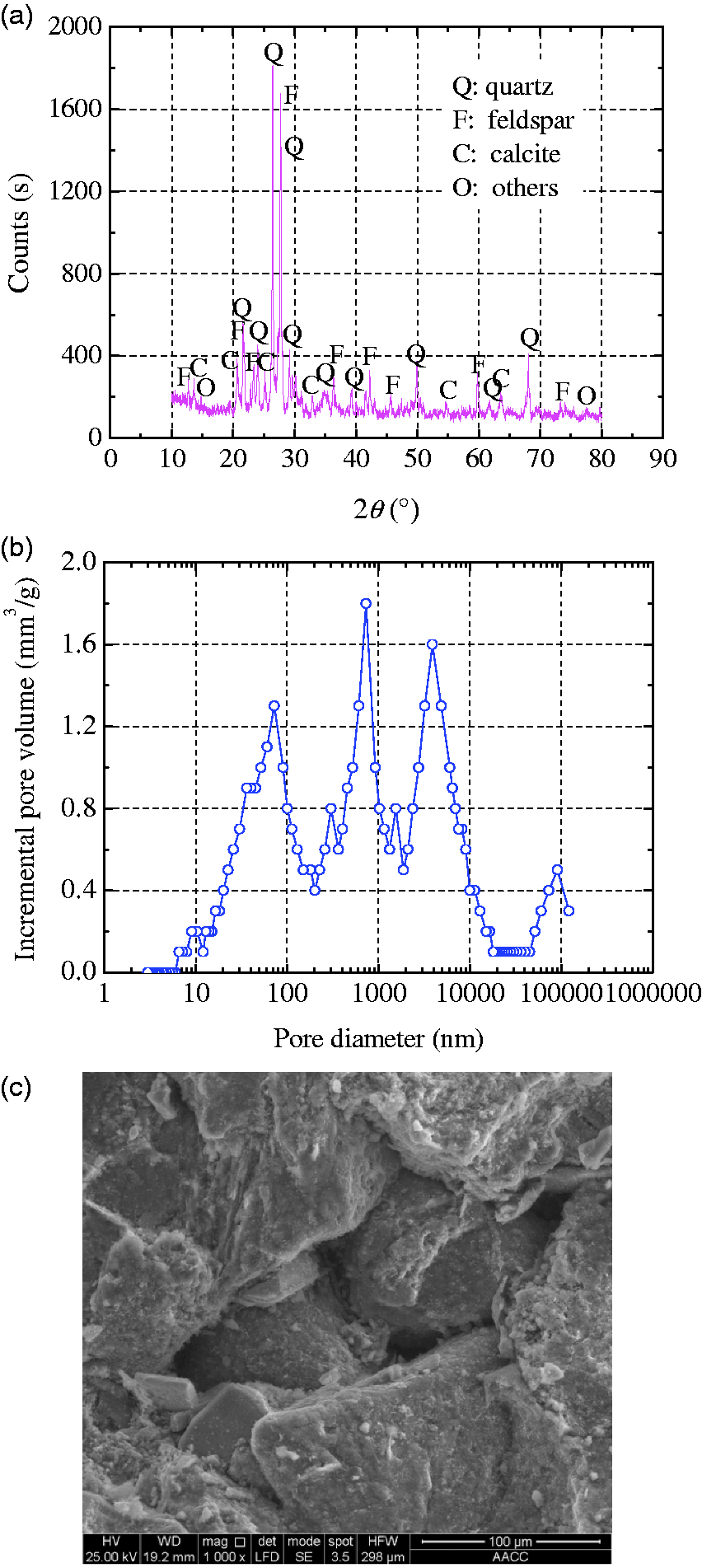
Sandstone samples were drilled from the original sandstone block. The samples were processed into cylinders with 100 mm in length and 50 mm in diameter. The error of the parallelism of the specimen ends is within ±0.02 mm. The sides of the specimen are smooth and straight within 0.3 mm over the full length of the specimen. Then samples needed to be processed further and a central borehole with 10 mm in diameter and 60 mm in length was drilled axially to the sample mid-point. The sketch and photograph of the sample design are shown in Figure 2. Subsequently, the surfaces and boreholes of the specimens were cleaned using the cotton swab. Then sandstone samples were sealed and sent to the laboratory for experimental testing. Before the nitrogen gas fracturing test, the sample was kept in an oven at 50℃ and vacuum for 12 h.
(a) Dimensions of sample and (b) real sample.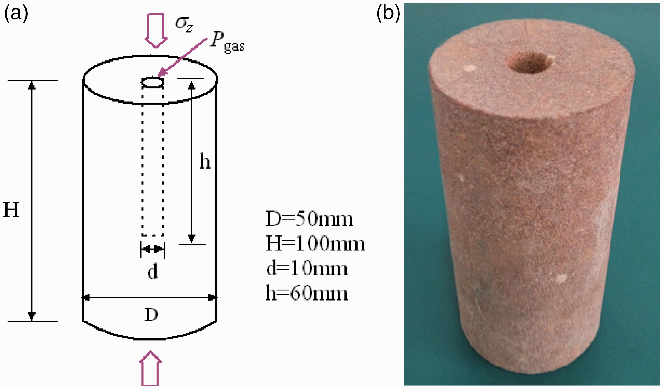
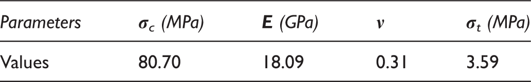
Mechanical parameters of the sandstone.
Apparatus
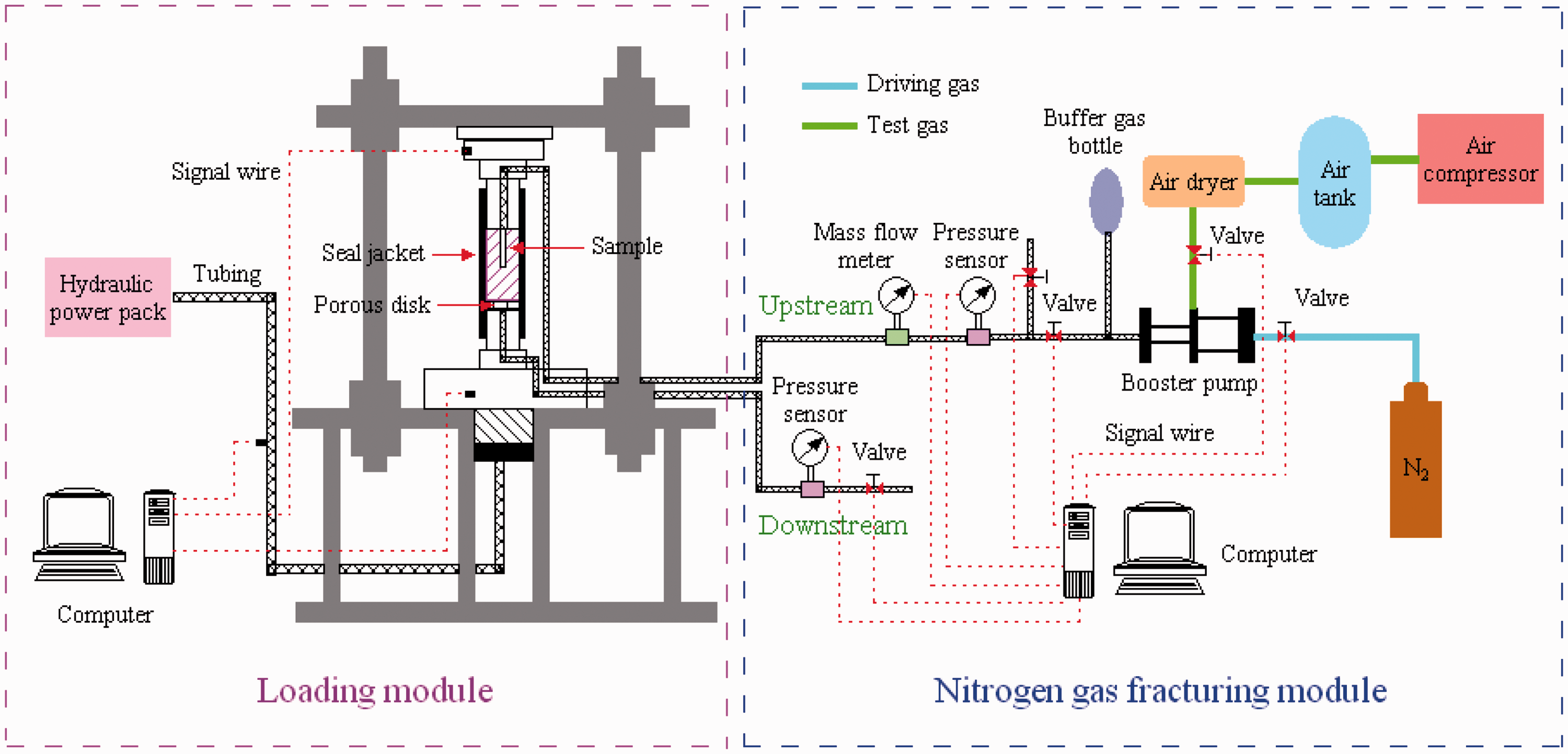
The nitrogen gas fracturing experimental system consists of two subsystems: a loading system and a gas injection system, and is shown in Figure 3. The detail introductions of the two subsystems show as follows:
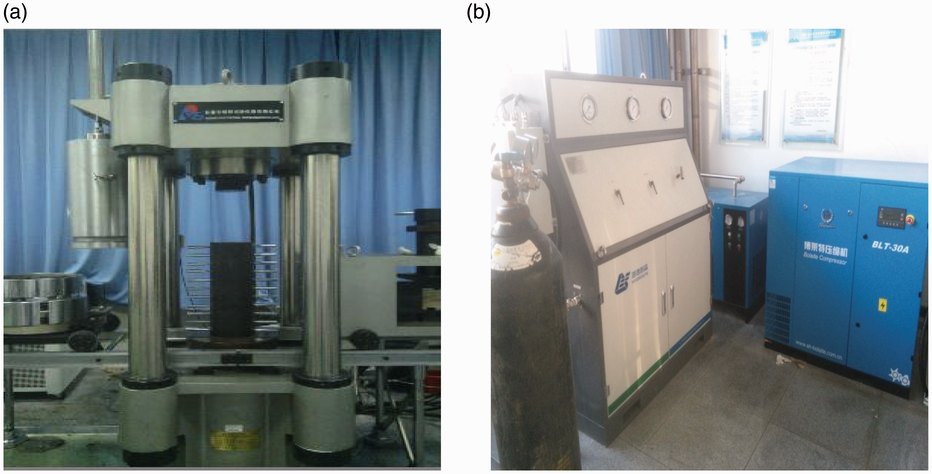
The TAWD-2000 electro-hydraulic servo-controlled rock mechanic testing system (Figure 4(a)) is served as a loading system, which includes a loading platform, a hydraulic power pack, and a stress console. This system has following technical parameters: the maximum axial force of 2000 kN, the maximum confining pressure of 80 MPa, the maximum axial displacement of 8 mm, and the maximum lateral deformation of 4 mm. The stress and strain of the sample are automatically and continuously measured by pressure transducers and extensometers and recorded in the computer. The accuracy of this system is ±1% for stress, ±1% for deformation. The nitrogen gas fracturing system mainly consists of an air compressor, an air dryer, a gas booster pump, an air tank, a buffer gas bottle, two mass flow meters, one pressure sensor, an N2 bottle, and a console (Figure 4(b)). The maximum of output gas pressure and standard flow are 80 MPa and 63 l/min, respectively. The data of the gas pressure and gas flow are automatically monitored and recorded in the computer. Diagram of the experimental system. Real test equipment. (a) Loading module and (b) nitrogen gas fracturing module.
Sealing method and experiment process
In order to describe the influence of the distribution of pore pressure on the fracturing behavior of the sandstone, three sealing methods of the sandstone sample were designed. Figure 5 shows three sealing methods of the specimens. Since the fluid penetration makes the phenomena of fracture initiation complex and prevents pure insight into the phenomena (Ito and Hayashi, 1991), nitrogen gas fracturing experiments were performed under a jacketed condition at first, where a borehole of the sample was jacketed with an impermeable jacket (see Figure 5(a)) to separate the nitrogen gas in the borehole from surrounding rock. The next two sealing methods focus on the uninstalled and installed sealing devices in the sides of the samples, which denote that there are gas filtration and no gas filtration in the sides of the samples, respectively. In order to compare with the second sealing method, in the third sealing method, the stainless steel hose clamp and the hydrogenated acrylonitrile butadiene rubber seal sleeve with the steel mesh were installed in sides of the sandstone specimens to prevent the gas leakage from the sides of the samples. Moreover, a new platen (see Figure 5(b)) was designed to use in nitrogen gas fracturing tests. A porous disk was welded on an end face of this new platen which contacts with the sample and eight small boreholes with diameter 2 mm were drilled in sides of this new platen. This new platen has two important functions. The first one is the gas pressure measurement of sides of the sample and the other is the residual gas emissions after the gas fracturing experiment. In three sealing methods, the seal method of the specimen bottom with the borehole is the same. The platen with double concentric O-ring encircling the central injection port (see Figure 5(c)) was designed and the screw thread was processed on the wall surface of the central injection port to connect the jacket A in the first sealing method. Besides, a hole in the side of the platen was drilled to interconnect the central injection port. It is worth noting that the central injection port does not connect with the other end of the platen. Then there is a gas source connector which was installed to the hole of the platen’s side to connect the platen to the gas fracturing system by the pipe line. The seal gum with high bond strength was used to seal the sample bottom and the platen end. Before the test, time of the air drying should not be less than 12 h.
Sealing methods of samples.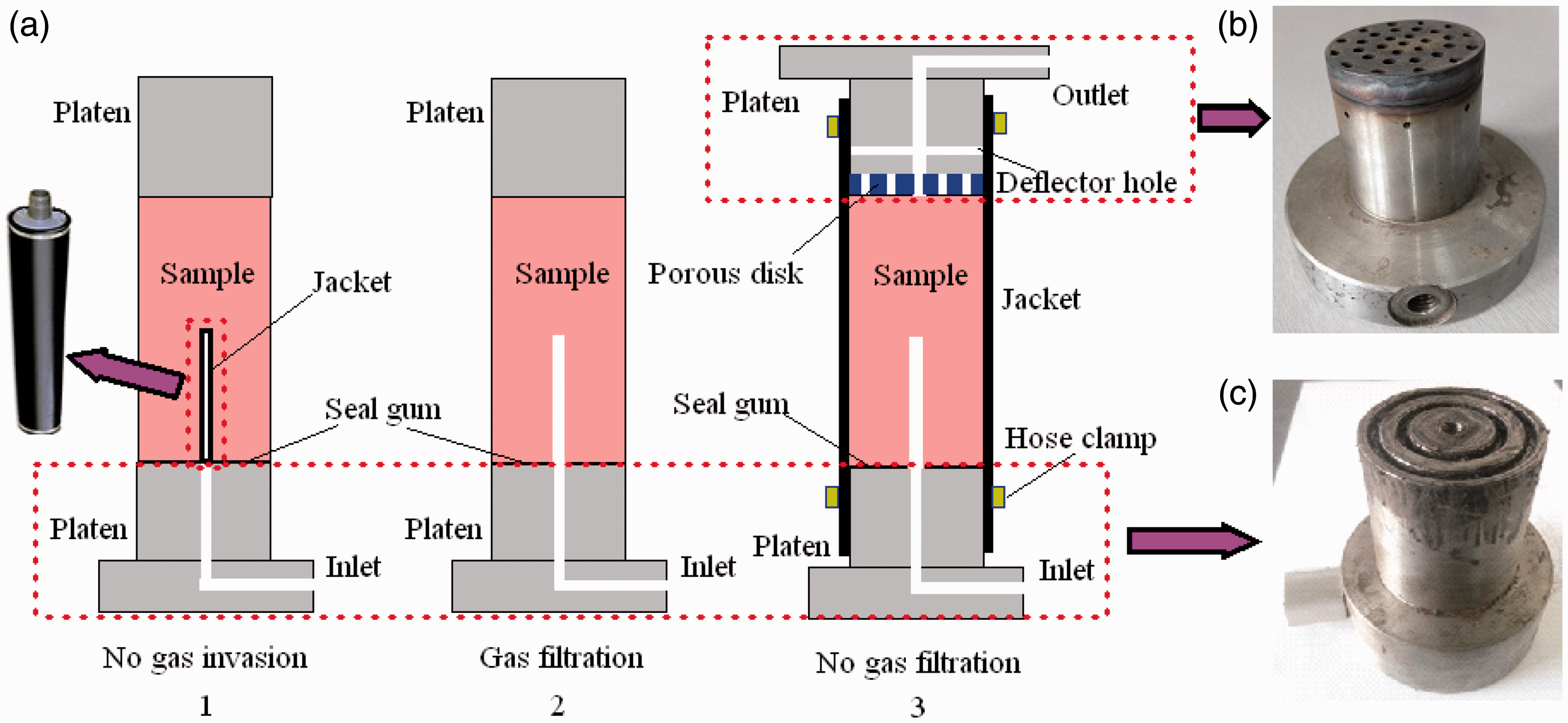
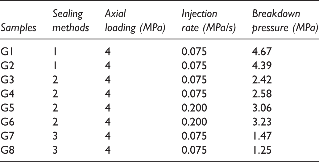
All nitrogen gas fracturing tests were performed under the room temperature and at the uniaxial stress of 4 MPa. When the preparations were completed, nitrogen gas was injected into the blind borehole at a constant injection rate until samples fail. In total, eight sandstone specimens are investigated. They were divided into three groups according to the sealing methods: two samples for the first sealing method, four samples for the second sealing method, and two samples for the third sealing method. In the second sealing method, effect of the injection rate on the fracture of samples was discussed and thus the four samples were divided into two groups once again to perform nitrogen gas fracturing tests of the two different injection rates. The typical change of injection pressure with time at the constant pressurization rate is shown in Figure 6. The peak pressure of injection pressure is regarded as the breakdown pressure of the sample.
Change of injection pressure with time.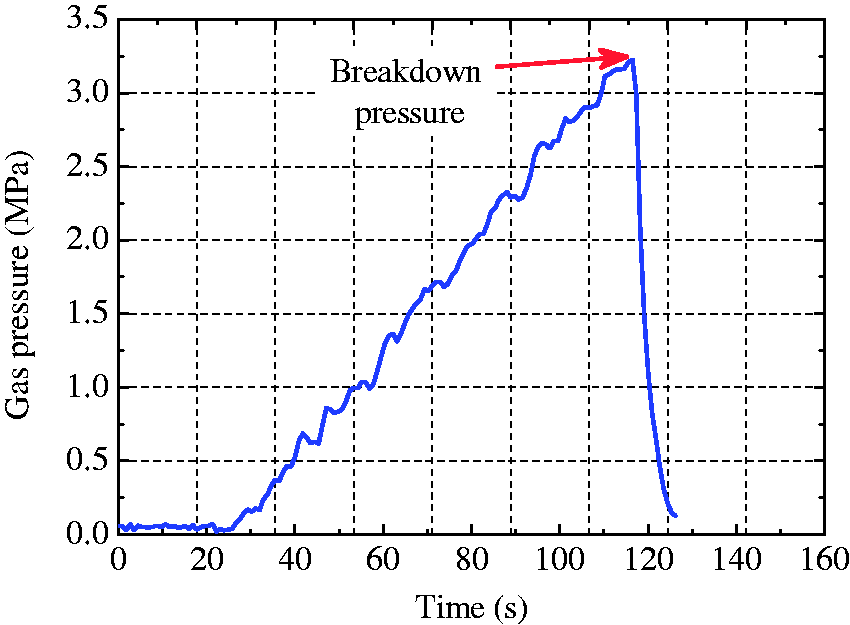
Results and discussion
Breakdown pressure
Summary of the experiments results.
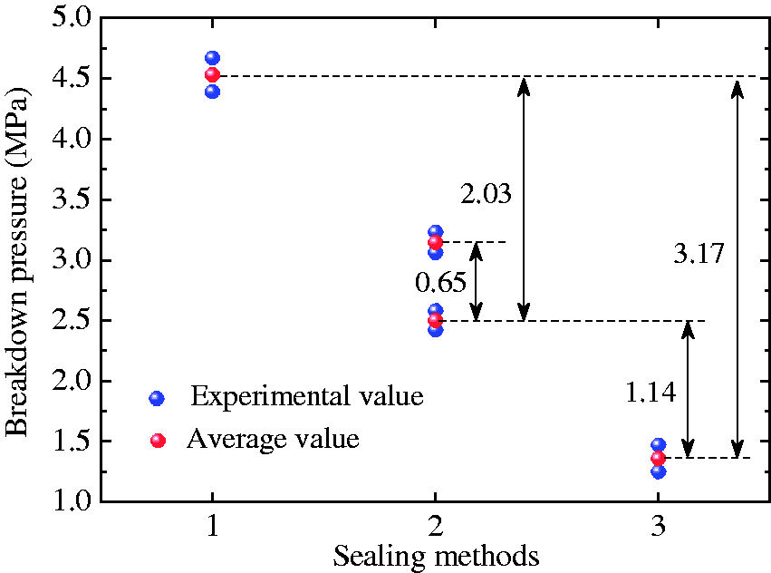
Effect of pore pressure distribution on the breakdown pressure of the sandstone.
As we know, in no gas invasion case, the pore pressure around the borehole certainly is zero. In no gas filtration, the pore pressure increases with the increasing of accumulation gas volume in pores, and the pore pressure of arbitrary point inside rock is considered to be equal to the borehole pressure when the specimen is broken down because at this moment the gas pressure value of sides of the sample which was obtained by the pressure sensor of the outlet is very close to the borehole pressure. However, for gas filtration case, when gas is injected in the borehole, an obvious pore pressure drop around the borehole appears due to gas leakage along the microcracks and connected pores. According to the previous researches (Ito, 2008; Ito and Hayashi, 1991), the pore pressure distribution has the relationship with the borehole pressurization rate and the pore pressure drop around the borehole is more serious with the increasing of the borehole pressurization rate. The pore pressure inside rock can be calculated as follows


Through the above-mentioned analysis, the pore pressure distribution in different cases when rock is broken down is presented in Figure 8, where the hydraulic diffusivity κ was assumed to be 2.303 × 10⁻⁴ m2/s for gas filtration case. With the pore pressure increasing, the pores can be inflated and the pore structure will become unstable. Thus, in this condition, the fracture tends to generate and propagate in the small borehole perturbation and a smaller injection gas pressure is needed for the failure of the specimen. This conclusion can be also confirmed by Xu et al. (2014). They studied the effect of the fluid pressure in the fracture on fracture propagation pressure and discovered that the fracture propagation pressure is reduced with the increasing of the fluid pressure coefficient which refers to the ratio of fluid pressure in the fracture to wellbore fluid pressure, and decreased by 75% with the fluid pressure coefficient increasing from 0 to 1. Therefore, the experimental results of this paper can be reasonably explained using the above-mentioned analysis. Analogously, in order to describe effect of the pore pressure distribution on the breakdown pressure in a better way, the pore pressure coefficient which represents the ratio of pore pressure to borehole pressure is regarded as a key parameter in the specimen failure process to be proposed. From Figure 8, the pore pressure coefficient in the same location increases in the following order: no gas invasion, gas filtration (0.2), gas filtration (0.075), and no gas filtration. The smaller the pore pressure coefficient is, the greater the breakdown pressure will be needed.
Pore pressure distribution when rock is broken down.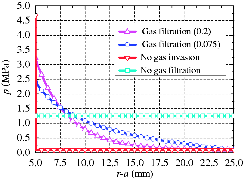
Failure mode
After nitrogen fracturing, the fracture complexity of the formation rock has significant influence on the fracturing design and well performance. Figure 9 displays the failure modes of specimens and the results show that the injection of nitrogen gas tends to induce the tensile fracture. Figure 9 also illuminates that the sealing method and injection rate have obvious effect on the failure modes of the sandstone sample. In no gas invasion case, the specimen fails along three main fractures and those main fractures run through the two ends of the specimen (Figure 9(a)). As to the gas filtration case, on the end face of the sandstone specimen, a typical bi-wing fracture is created for both the two injection rates. On the side face of the sandstone specimen, multiple fractures are generated by the low injection rate and the simple fracture is produced by the high injection rate. But the length of the fracture is larger when the injection rate is greater (Figure 9(b) and (c)). When the side of sample has no gas filtration, three main fractures and many small cracks are observed around the injection borehole of the samples. The main fractures run through the two ends of the specimen (Figure 9(d)). Compared with the first two sealing methods, the fracture patterns of the specimens in no gas filtration case are more complex and have higher surface area-to-volume ratio which can be helpful for improving the permeability of rock and increasing the seepage paths of gas. Besides, the induced fracture geometry of side face in gas invasion case is more circuitous than in no gas invasion case. The tortuous fracture also contributes to increasing the surface area of the fracture that is a key parameter to reflect the ability of the fluid migration inside rock (Alpern et al., 2012; Hou et al., 2016a)
Failure modes of the sandstone samples. (a) G1, (b) G3, (c) G6, and (d) G7.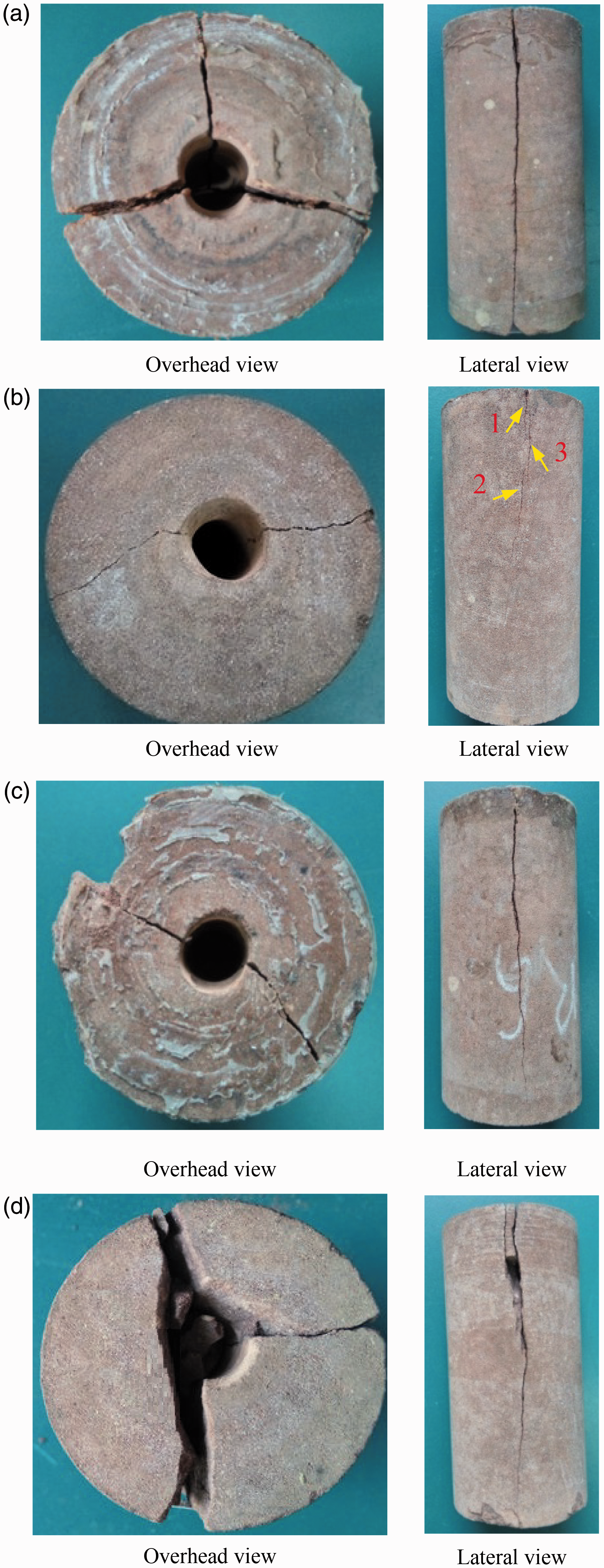
There are two main factors causing these differences about the failure modes of the samples: borehole pressure and pore pressure; thus the comprehensive consideration of the two factors is needed. In no gas invasion case, the pore pressure coefficient is zero, hence the specimen is in the steady state. The high borehole pressure can induce the large circumferential stress and the rupture of the sample is relatively violent. In gas invasion case, the required borehole pressure for the destruction of the sample is relatively small due to the unsteady state of the sample induced by pore pressure. The rupture degree of the sample is determined by borehole pressure and pore pressure. Usually, the greater the pore pressure is, the more unsteady the sample is. Therefore, when the pore pressure of the specimen is high, the sample can produce violent destruction resulting in the complex fracture even though the borehole pressure is small, for example the failure process of the sample in no gas filtration case. The difference of the failure mode between the low injection rate and high injection rate is because that the pore pressure has enough time to generate the secondary cracks at the low injection rate and the high borehole pressure can induce the large crack at the high injection rate. The results indicate that the rupture degree of the sample is mainly controlled by the borehole pressure at high injection rate and controlled by the pore pressure at low injection rate.
Microstructure of fracture surface
In order to investigate the influence of the pore pressure distribution on the microstructure of fracture surface, the samples of the same location on the fracture surface were obtained (see Figure 10) and then the SEM experiments were performed.
Location of sample used for SEM experiments on fracture surface. SEM: scanning electron microscope.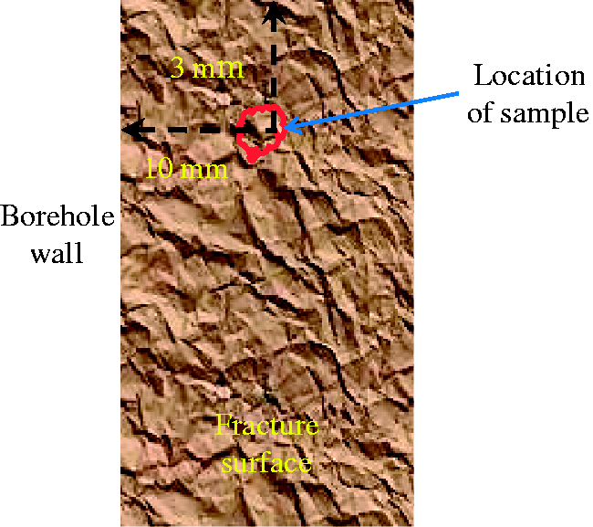
Figure 11 shows the SEM images of the fracture surfaces in no gas invasion case. The clear and rough tensile fracture can be observed in the pore structure using magnifications of 1000. However, after magnifying 3000 times, the tensile fracture morphology becomes smooth and the microfractures can hardly be observed. The result illustrates that the borehole gas pressure only impacts on the macroscopic crack of the sample and is not enough to generate influence on the internal pore structure of the sample.
SEM images of the fracture surfaces in no gas invasion case. SEM: scanning electron microscope.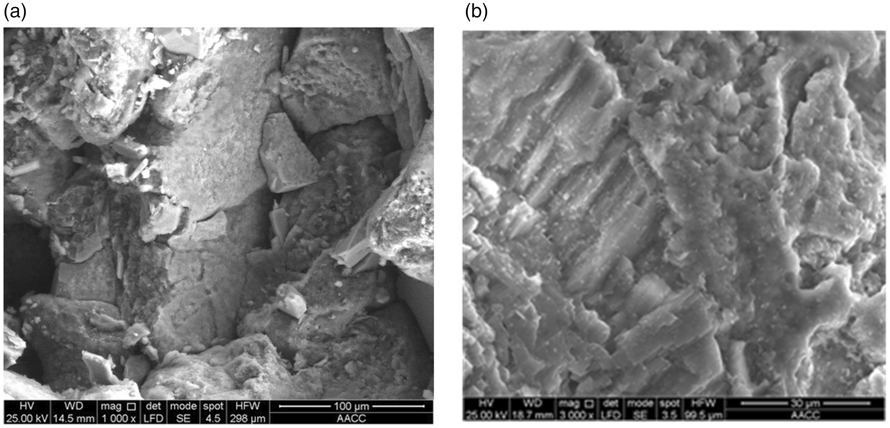
The SEM images of the fracture surfaces in gas filtration case are shown in Figure 12. Using magnification of 3000 times, only single microfissure can be found on the fracture surface for both the low injection rate (Figure 12(a)) and high injection rate (Figure 12(b)), and there are no complex multicracks. The result indicates that the interior structure in the sandstone is broken under the action of the pore pressure generated during gas filtration, and then these new microcracks are produced. But the pore pressure is relatively small because of serious gas filtration along microcracks and connected pores in the sandstone, thus the initiation and propagation of the microcrack are limited.
SEM images of the fracture surfaces in gas filtration case. (a) G3 and (b) G5. SEM: scanning electron microscope.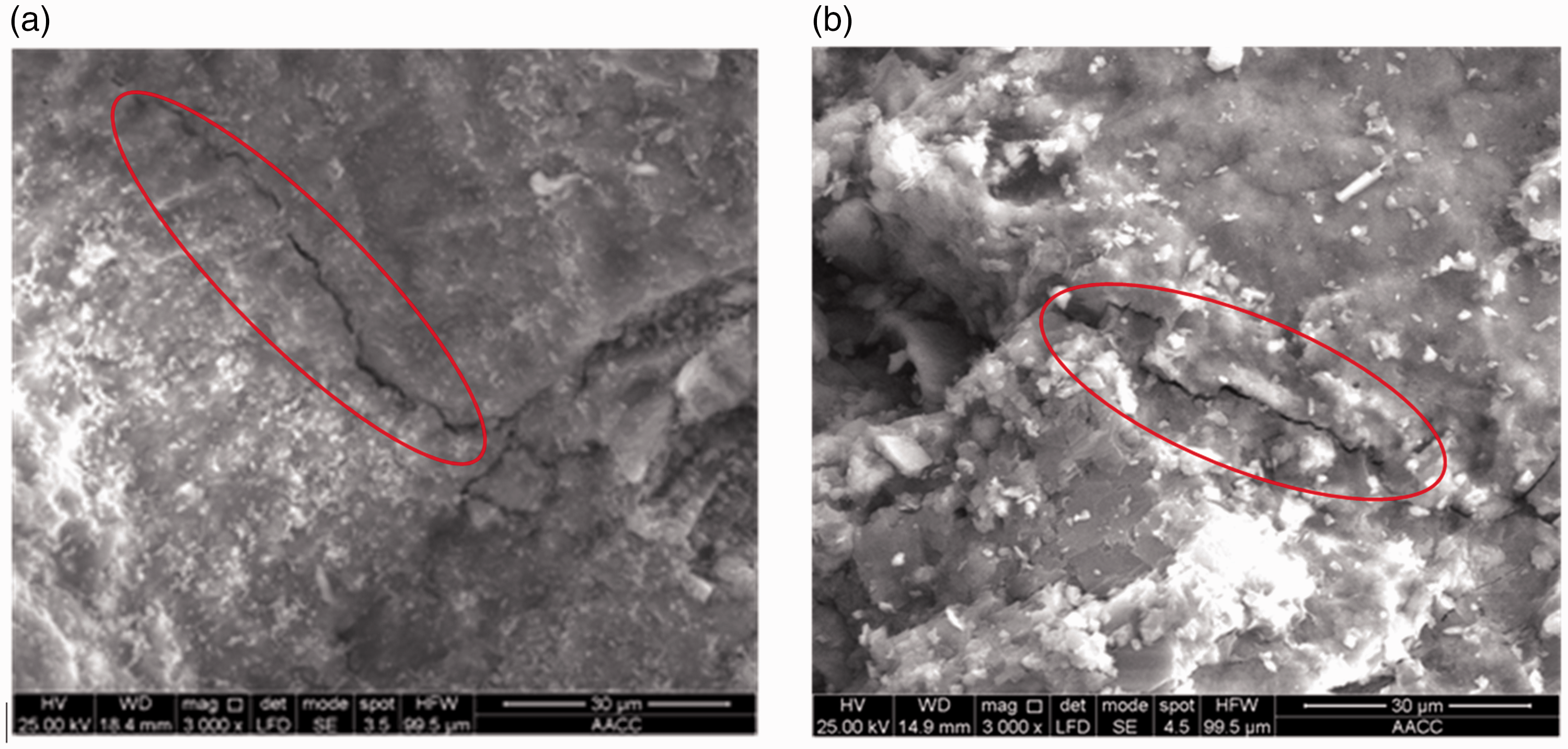
Figure 13 displaces the SEM images of the fracture surfaces in no gas filtration case. Excitedly, multicracks and cross cracks are observed in the microstructure of fracture surface, which can increase the permeability of the sandstone and contribute to the migration of gas or oil in reservoirs after nitrogen gas fracturing. Besides, complex multi- and microfractures increase the high surface area-to-volume ratio which can promote desorption of adsorbed gas in some organic matter reservoirs. The main reason for the formation of complex microcracks is high pore pressure distribution which creates enormous instability of internal pore structure. This enormous instability is favorable to the fracture initiation, growth, and coalescence.
SEM images of the fracture surfaces in no gas filtration case. SEM: scanning electron microscope.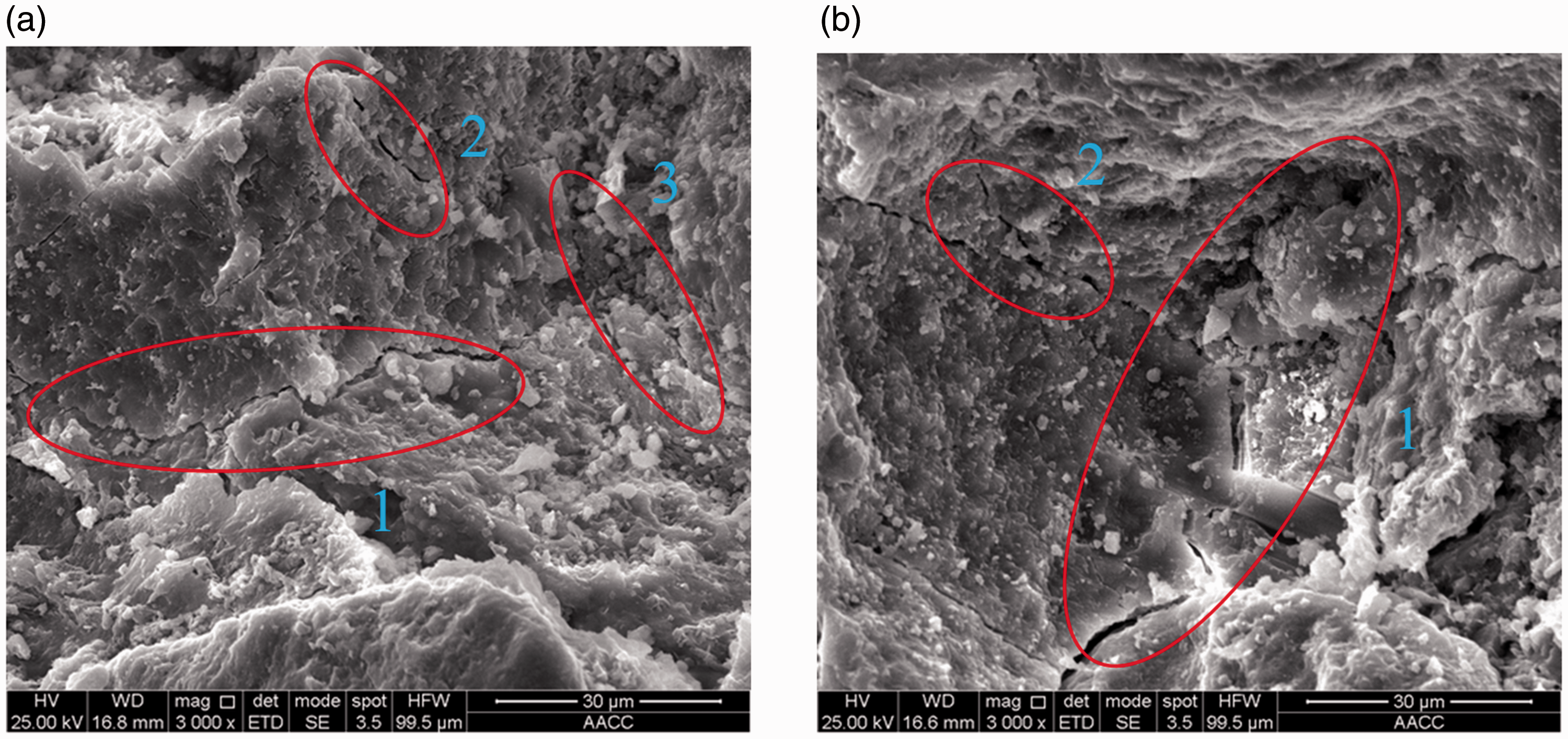
Application
According to the experimental results, reducing the amount of gas filtration for the permeable material can be effective in decreasing the breakdown pressure and increasing the complexity of the fracture in nitrogen gas fracturing, which contributes to reducing the demanding requirements of fracturing equipment during fracturing process and improving gas production after nitrogen gas fracturing. In the tight and unconventional gas reservoirs, there are quite a number of induced and natural cracks although the reservoir matrix is ultralow porosity and permeability. These fractures are beneficial for the economic and efficient development of gas reservoir; however, in nitrogen gas fracturing, they will also lead to serious nitrogen gas filtration which decreases the fracture pressure and increases the difficulty of the fracture propagation. Therefore, in this paper, the method of the special graded particles is proposed to temporarily plug the fractures and it is schematically presented in Figure 14. It is worth noting that the temporary plugging of the fractures during fracturing process and the propping of the fractures after fracturing are considered together in this method. Some literatures have reported that graded particles are used to prevent serious formation damage by reducing the loss of drill-in fluid (Kang et al., 2014) and increase reservoir permeability by preventing the closure of the dilated natural fractures (Keshavarz et al., 2015, 2014; Khanna et al., 2013). However, to our best knowledge, few papers have been published on the comprehensive consideration of the above two issues. The detail of the method is introduced as follows.
Diagram of the plugging and propping of the special graded particles.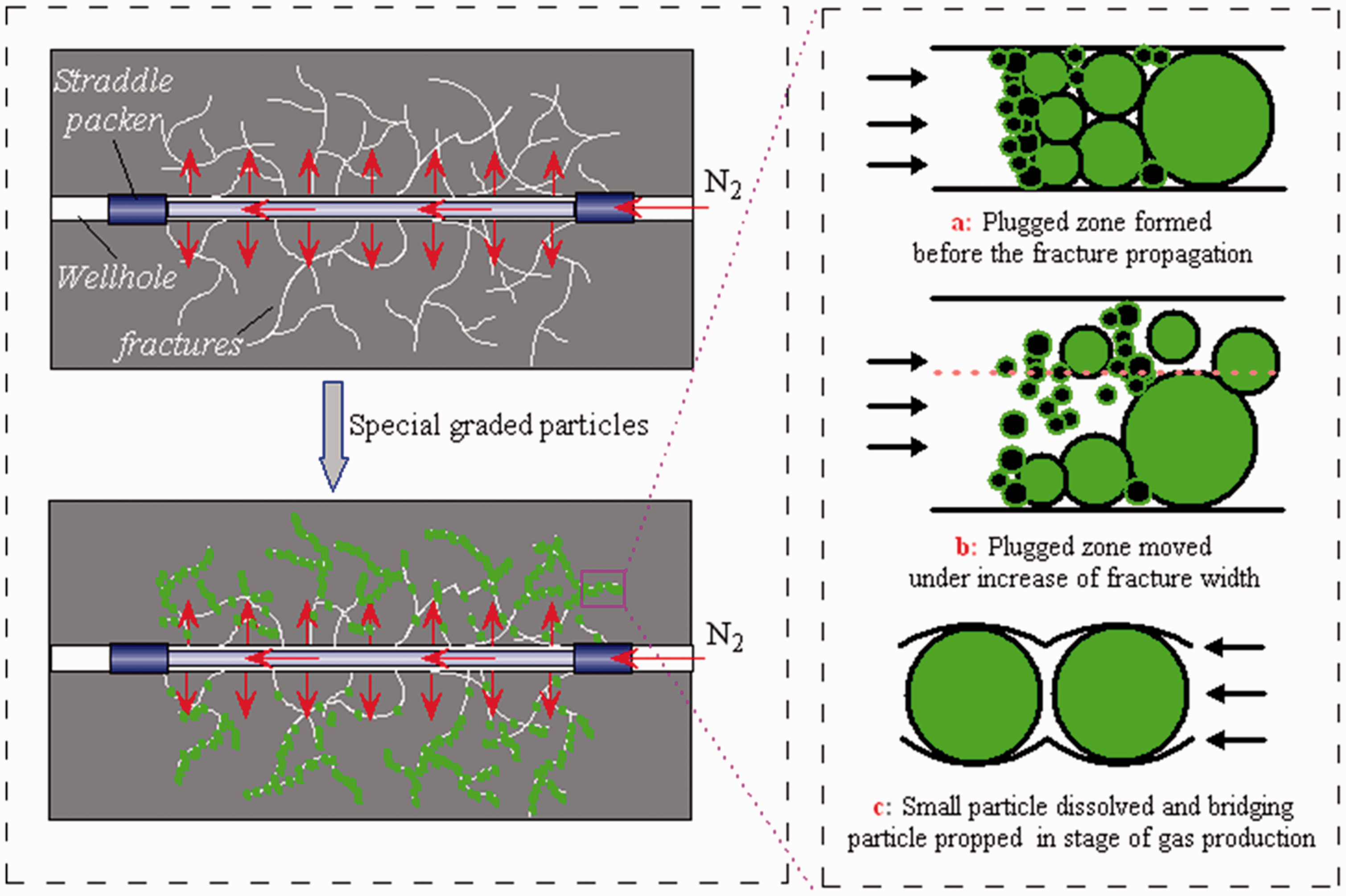
Before nitrogen gas fracturing, the special graded particles are added into the fracturing fluid in advance. Apart from the bridging particle which is the rigid particle, other particles can be dissolved in acidizing treatment. According to the plugging and sealing effect of the special graded particles, a tight fracture plugged zone with the permeability near zero can be formed and prevent the further filtration of fracturing fluid (Figure 14(a)). With increasing of the injection volume of fracturing fluid, the fracturing fluid pressure increases rapidly in the tight fracture plugged zone. When fracturing fluid pressure is larger than the fracture propagation pressure, the fracture propagation will be induced. In this process, the fracture can be inflated and the fracture width increases which is usually in a very short time. In this short time, the special graded particles can move forward along the flow direction of the fracturing fluid (Figure 14(b)), and then the next tight fracture plugged zone will be formed. This cycle makes the formation of the complex fracture network in the reservoir. After fracturing, the other particles are dissolved by the acidizing treatment and the bridging particles are leaving in the fractures to prop the fractures width (Figure 14(c)). Therefore, the permeability of the reservoir can be improved to a large extent and the gas production will also increase dramatically.
Conclusions
Through the findings of the study, the following main conclusions can be drawn:
The breakdown pressure of the sandstone reduces in turn in: no gas invasion, gas filtration (0.2 MPa/s), gas filtration (0.075 MPa/s), and no gas filtration. In no gas filtration case, the breakdown pressure value of the sample decreases by 69.98 and 45.6% in comparison to the no gas invasion and gas filtration case, respectively. The results indicate that decreasing the amount of gas filtration and increasing pore pressure is effective in reducing the breakdown pressure. The larger the pore pressure coefficient is, the smaller the breakdown pressure will be needed. The pore pressure can increase effectively the complexity of the fracture geometry. The failure mode is mainly controlled by borehole pressure at high injection rate and controlled by pore pressure at low injection rate. The pore pressure can also promote the initiation of the microcrack and high pore pressure distribution is helpful to form complex multifractures network. Based on the experimental results, the method of the special graded particles is proposed to use in field. The temporary plugging of the fractures during fracturing process and the propping of the fractures after fracturing are considered together in this method. The method is expected to reduce the fracture propagation pressure and produce the complex fracture network to improve the gas production of the reservoir.
Footnotes
Acknowledgments
We would like to thank all editors and anonymous reviewers for their comments and suggestions.
Declaration of conflicting interests
The author(s) declared no potential conflicts of interest with respect to the research, authorship, and/or publication of this article.
Funding
The author(s) disclosed receipt of the following financial support for the research, authorship, and/or publication of this article: The authors gratefully acknowledge the financial support from the Fundamental Research Funds for the Central Universities (Grant No. 2017BSCXB51).