
Abstract
Liquid nitrogen has emerged as a promising fracturing medium for unconventional natural gas extraction, particularly in the context of coalbed methane extraction, generating significant interest in recent times. In this paper, we analyze the acoustic emission (AE) characteristics of coal samples treated with liquid nitrogen under three-point bending load conditions using indoor experiments and field investigations. We investigate the impact of liquid nitrogen on coal samples by analyzing AE data. The mechanical properties of coal samples with varying initial temperatures were tested under three-point bending load conditions after treatment with liquid nitrogen. The load-displacement curve was analyzed to study the mechanical properties of the coal samples after treatment with liquid nitrogen. Through indoor three-point bending experiments, data analysis, and knowledge of mechanics, we systematically investigated the changes in mechanical properties caused by liquid nitrogen treatment under different conditions. The results demonstrate that the application of liquid nitrogen has significant impacts on the mechanical and AE characteristics of coal samples. The load-displacement curve indicated that the mechanical properties of the coal samples changed after treatment with liquid nitrogen. The AE experiment revealed regular changes in vibration and energy parameters of coal samples after liquid nitrogen treatment under different conditions. We further investigated the changes in mechanical properties and deformation characteristics of coal samples after undergoing liquid nitrogen freezing and thawing in differing environments. Graphs such as load-displacement curves, load-time curves, cumulative vibration count-energy count graphs, and RA-AF density distribution diagrams visually demonstrated the changes in mechanical properties and deformation characteristics. Through an integrated approach of indoor experiments, data analysis, and knowledge of mechanics, our study provides a better understanding of the behavior of coal samples under different conditions. This understanding can contribute to the development of safer and more efficient methods for extracting coalbed methane.
Introduction
As a strategic resource of the nation, the exploration and utilization of oil and gas resources are closely related to national development. However, with the continuous development of the economy and the progress of modern industrialization, conventional oil and gas resources can no longer meet the needs of development. Therefore, it is of great significance to strengthen the exploration and utilization of unconventional natural gas resources (Bai et al., 2022a, 2022b; Li et al., 2023).
Coalbed methane (CBM) is an important hydrocarbon gas composed primarily of methane and stored in coal seams, primarily adsorbed onto the surface of coal matrix particles (Bai et al., 2022c; Xue et al., 2023a). In addition to being found in coal pores, CBM can also be dissolved in coalbed water. As a valuable associated mineral resource of coal, CBM boasts a heating value comparable to that of conventional natural gas (Mu et al., 2015). As an associated mineral of coal, CBM poses significant challenges to the development and utilization of coalbeds. As coal seams are excavated at greater depths, the pressure produced by the coal and CBM increases, which can result in gas explosions. Therefore, developing CBM not only eases resource pressure but also helps prevent or minimize potential gas accidents during coal mining operations. Coal is a multi-porous medium composed of pores, fractures, and matrix. This makes it inherently difficult to extract and transport CBM from coalbeds. As such, increasing permeability in CBM reservoirs is necessary to optimize CBM production (Jha et al., 2022; Zou et al., 2015).
Currently, the primary method for increasing permeability in unconventional natural gas reservoirs is hydraulic fracturing. Hydraulic fracturing is effective in fracturing hard rock reservoirs and can increase the production efficiency of CBM (Xue et al., 2023b). However, its recovery rate is relatively low compared to CBM reserves (Xie et al., 2010). Moreover, hydraulic fracturing is particularly limited in soft CBM reservoirs, where it is difficult to achieve significant increases in permeability. In addition, the hydraulic fracturing process involves a large amount of chemical additives in its fracturing fluid, such as cross-linking agents and thickening agents. If the resulting wastewater is not disposed of properly, it can cause pollution and seriously affect the local groundwater and soil quality, ultimately impacting the health of the residents. Many of CBM resources are located in drought-prone areas where water resources are scarce. Hydraulic fracturing requires large amounts of water to be used, exacerbating existing pressure on local water resources (Ishida et al., 2004). With the improvement of living standards, people are increasingly pursuing a high-quality and healthy life, and environmental protection is receiving more attention. Due to concerns over its potential environmental impacts, hydraulic fracturing technology is becoming restricted in many countries and regions. As a result, countries are researching new technologies for the efficient extraction of unconventional natural gas, with the aim of replacing hydraulic fracturing methods.
In order to achieve better extraction of unconventional natural gas and maximize its economic benefits, while minimizing the impact on the environment, foreign countries have first proposed the concept of waterless fracturing technology, which differs from traditional methods used in petroleum extraction. This technology has been successfully applied in the field, solving some of the difficulties previously encountered with hydraulic fracturing, and has demonstrated significant improvements in production efficiency with clear results (Guo et al., 2020; Liu et al., 2023; Ma et al., 2022). Abel was the first to conduct fracturing experiments on shale reservoirs using nitrogen (Abel, 1981). The nitrogen-based waterless fracturing technology involves using nitrogen as a fracturing medium to increase permeability of the target coal seam and achieve higher yields without using water or solid particles. As a result, issues such as water sensitivity and solid particle blockage are avoided. However, the density of nitrogen presents challenges when using proppants, which are agents used to prop open fractures. Without effective propping, the fractured portions can close over time, resulting in reduced efficiency and lower economic benefits.
In recent years, many scholars have conducted numerous studies on liquid nitrogen and its use in fracturing. In the late twentieth century, Ishida et al. successfully used liquid nitrogen as a fracturing fluid for enhancing oil reservoir stimulation, which resulted in a significant increase in production efficiency (Ishida et al., 2016). Halbert proposed injecting liquid nitrogen into the production well after fracturing, which lowers the underground temperature of the target reservoir to freezing point, and then injecting high-temperature steam to melt the frozen reservoir (Halbert, 1971). Results showed that this freeze-thaw method can effectively promote secondary development of fracture networks in the reservoir, leading to a significant increase in production efficiency. Sun et al. (2021) addressed the central issue of thermal damage in granite under thermal cycling. This study employed a multi-faceted approach, incorporating theoretical analysis, physical experiments, and numerical simulations, to explore the macro- and micro-damage characteristics of high-temperature granite when exposed to liquid nitrogen cryogenic cooling and thermal shock. Ge et al. (2021) investigated the changes in stress state around the wellbore, the damage characteristics of high-temperature granite under the low-temperature effect of liquid nitrogen, and the fracture features and crack morphology of granite under the low-temperature-pressure coupling effect of liquid nitrogen injection into a high-temperature reservoir. The findings of this study demonstrate that as the initial temperature rises, the temperature stress surrounding the wellbore steadily increases and the associated tensile stress zone within the reservoir expands accordingly. The effects of inlet pressure and ambient pressure on the tensile stress generated by liquid nitrogen cooling are minimal. Wang et al. (2023a, 2023b) through conducting cryogenic treatment on granite, discovered that liquid nitrogen can significantly reduce the mechanical properties of granite and result in the formation of a more complex network of microcracks in the granite. McDaniel et al. (1997), in their field test of liquid nitrogen fracturing in CBM reservoirs, observed a significant increase in gas permeability and methane production after initial fracturing, but with less than satisfactory sustained gas production. Shao et al. (2021) conducted experiments on the effect of liquid nitrogen cryogenic shock on the acoustic wave propagation in coal rock. The study found that after undergoing liquid nitrogen treatment, the coal rock exhibited a significant decrease in acoustic wave velocity and amplitude. Therefore, the cryogenic shock effect produced by liquid nitrogen can cause significant changes to the internal structure and mechanical strength of coal rock. In addition, some researchers investigated the effect of liquid nitrogen freeze-thaw cycles on the extension of primary fractures and compressive strength in coal (Li et al., 2015; Zhao et al., 2018). The study found that the freeze-thaw cycles with liquid nitrogen have a promoting effect on the development of coal fractures. In research on the mechanical properties of rocks and changes in cracks, Kaiser (1950) first proposed that metal samples do not generate significant acoustic emission (AE) until they are subjected to stress that exceeds the previously applied stress when reloaded after unloading; AE only occurs when the stress on the sample reaches its maximum pre-existing stress. Schofield began studying AE technology to verify Kaiser's findings and measure AE sources. Goodman (1963) used experiments to verify that rocks exhibit the Kaiser effect and showed that it can be used to determine the three-dimensional stress distribution history in rocks. Subsequently, it was found that Goodman's experimental method was too simplistic and yielded inaccurate results. Through repeated experiments, the technology of observing the initiation and growth of internal cracks in rocks through AE has become increasingly mature (Holcomb and Costin, 1986; Kanagawa et al., 1977). Meanwhile, the study of AE in laboratory rocks has attracted widespread attention, particularly in the investigation of the process and mechanism of brittle failure in rocks, with numerous scholars making important contributions (Kim et al., 2015; Lockner, 1993; Nasseri et al., 2006; Zhou and Zhang, 2021). Thus far, research has primarily focused on permeability and porosity of coal samples, with less attention being paid to the properties of coal and rock after liquid nitrogen treatment. This paper aims to study the AE characteristics of coal samples under three-point bending conditions after liquid nitrogen treatment at different initial temperatures through AE testing.
Experimental materials and procedures
Acoustic emission theory
The purpose of this experiment is to use an AE detector to study the properties of coal and rock after being treated with liquid nitrogen. AE occurs when energy is suddenly released from a local source in a material, resulting in transient elastic waves. This phenomenon commonly occurs during the deformation and fracture processes of various objects. However, the AE signals from many materials are often too weak for the human ear to detect directly, and therefore require sensitive electronic instruments for detection, recording, and analysis. Through the AE method, the source of the AE can be identified. Figure 1 provides a visual depiction of the installation of an AE probe in a rock experiment. Once installed, the probe can detect and record the ultrasonic waves generated by the rock specimen under different loading conditions. These signals are then transmitted to an AE monitoring system, where they can be further processed and analyzed using various techniques such as parameter analysis or waveform analysis. The AE sensor detects this displacement, converting the mechanical vibration of the material into electronic signals. These signals are then amplified by the preamplifier, processed by the data processor, and finally displayed and analyzed using the recording and display system while awaiting the next AE signal. This approach can help understand the AE mechanism of materials.
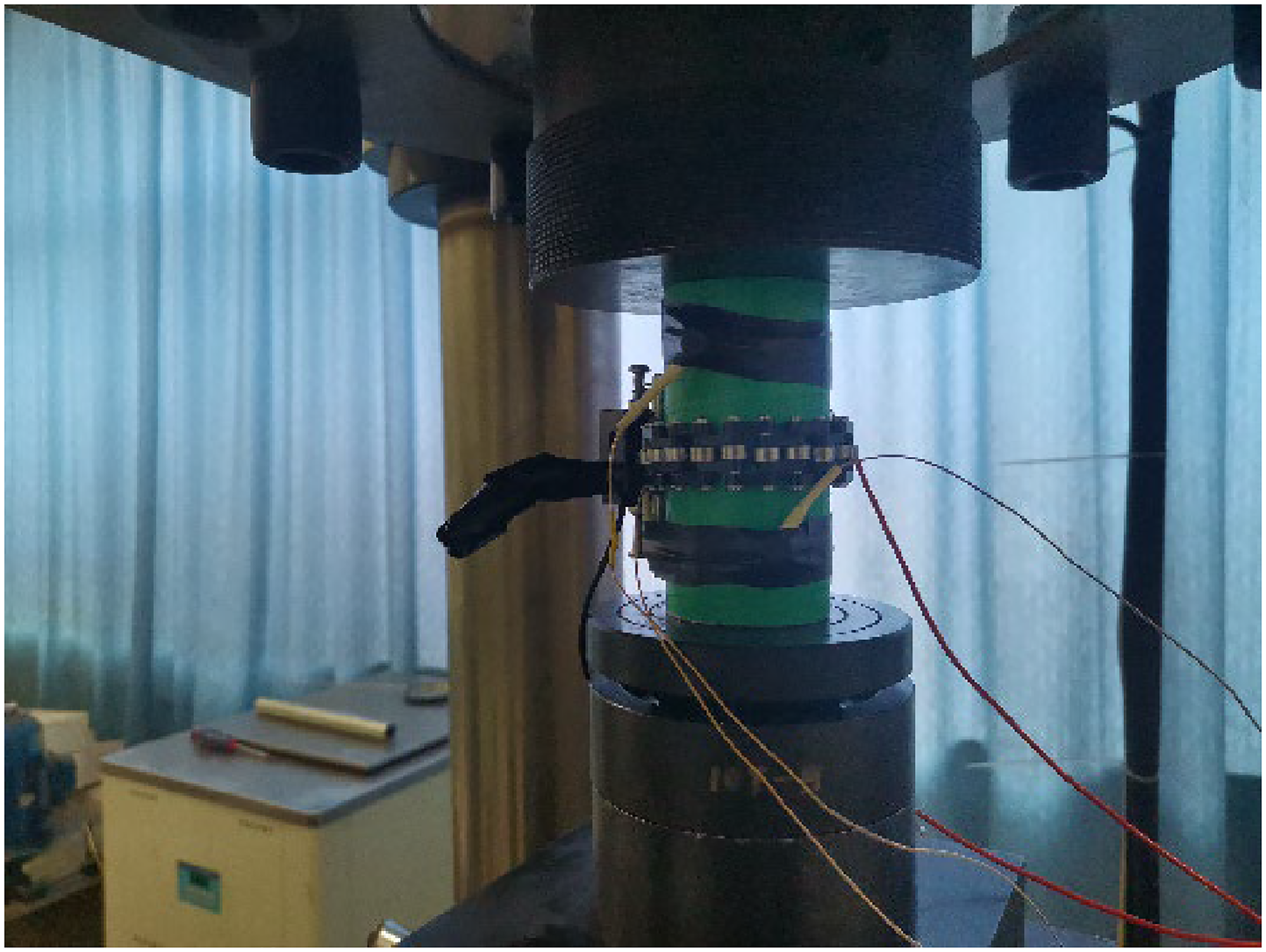
Installation of acoustic emission probe.
Experimental equipment and scheme
In this experiment, coal samples were prepared into a semi-circular disk with a thickness of 30 mm and a diameter of 76 mm, with an artificial cut length of 14 mm across the center of the disk, as shown in Figure 2. Each type of coal sample was divided into two groups: temperature and cyclic groups. The temperature group was meticulously sub-divided into six subgroups according to specific temperature conditions: untreated at room temperature, untreated at room temperature followed by liquid nitrogen cooling, heated to 40 °C followed by liquid nitrogen cooling, heated to 60 °C followed by liquid nitrogen cooling, heated to 80 °C followed by liquid nitrogen cooling, and heated to 100 °C followed by liquid nitrogen cooling. The cyclic group was further sub-divided into groups that underwent 3, 5, 7, 9, and 15 cycles, respectively; wherein high-temperature treatment till 80 °C followed by liquid nitrogen cooling was considered as one cycle. There were two sets of samples for each condition. The temperature group was labeled as 20-1 untreated, 20-2 untreated, 20-1, 20-2, 40-1, 40-2, 60-1, 60-2, 80-1, 80-2, 100-1, and 100-2. The cyclic group was labeled as 3-1, 3-2, 5-1, 5-2, 7-1, 7-2, 9-1, 9-2, 15-1, and 15-2. The equipment used for sample preparation and liquid nitrogen treatment is shown in Figure 3.
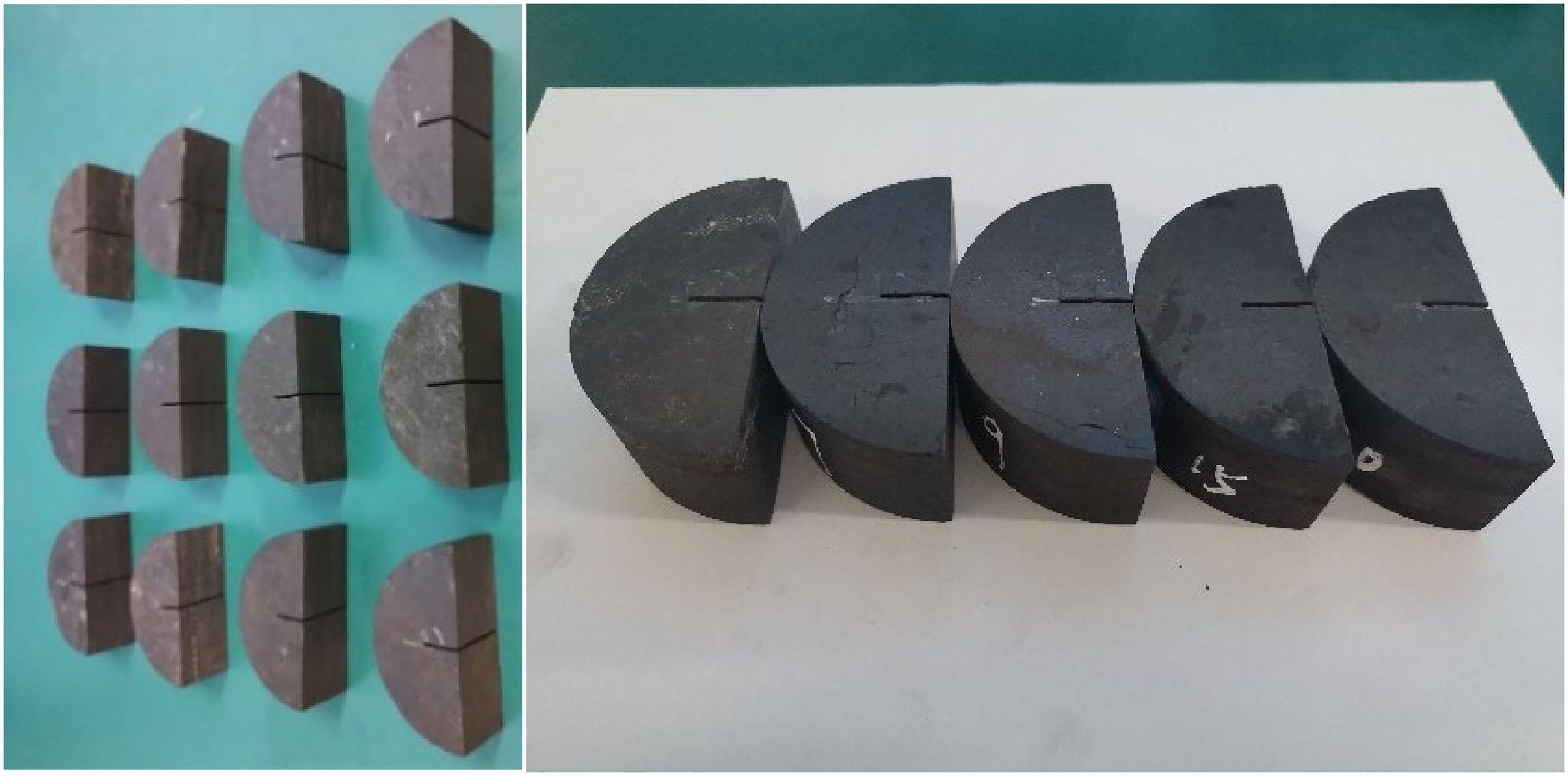
Coal sample diagram.
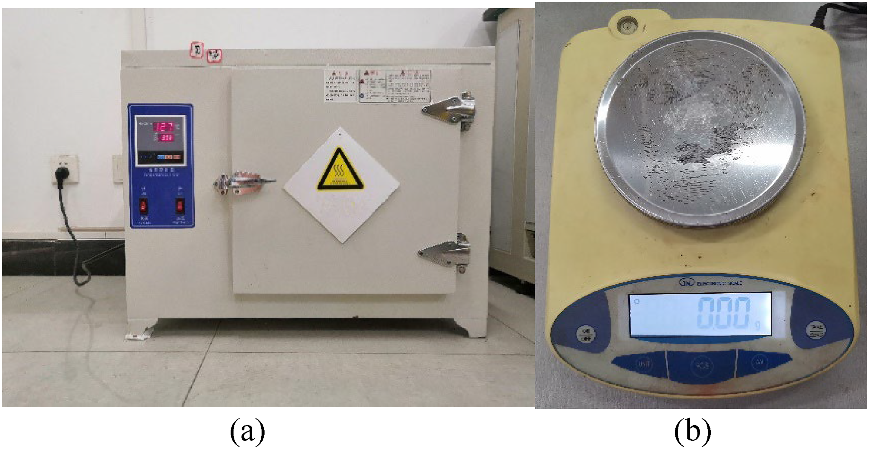
Auxiliary equipment. (a) Heating box, (b) electronic scale.
Subsequently, the processed rock samples were subjected to three-point bending tests using a device shown in Figure 4. The sample was placed on a pressurizing machine and subjected to pressure, while the changes in rock deformation and corresponding force values were displayed on a computer.
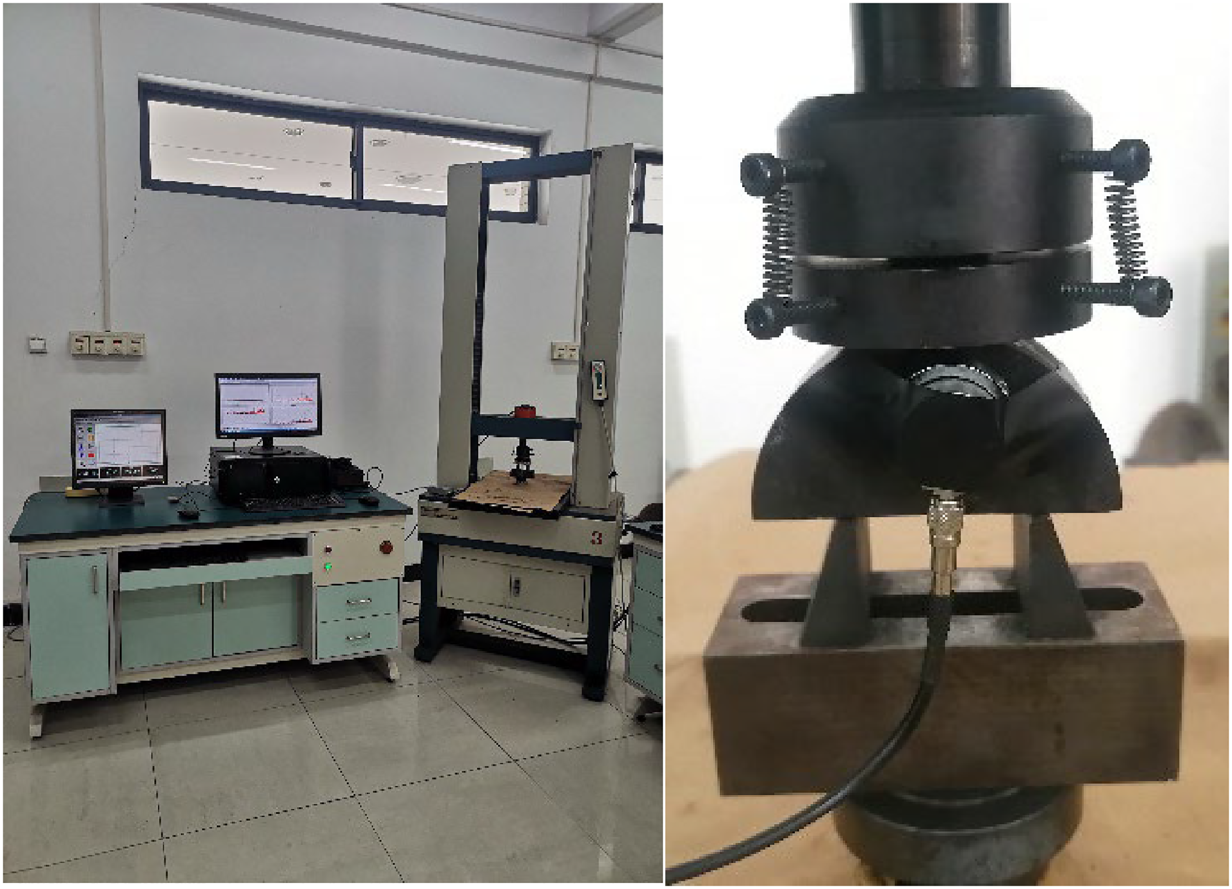
Experimental equipment diagram (electronic universal testing machine).
Within the realms of applied mechanics and industrial engineering, the three-point bending test is a frequently employed method. In keeping with the guidelines established by the International Society for Rock Mechanics (Culshaw and Ulusay, 2015), this experiment was conducted. After subjecting the coal rock samples to liquid nitrogen freeze-thaw cycles, they were assigned identification numbers and subjected to three-point bending tests. The treated coal rock samples were placed between the upper and lower press plates of an electronic universal testing machine, ensuring that their central axis was aligned with that of the testing machine's. The testing machine was then started, and the clamping screws on both sides of the split clamp were loosened. The loading process was applied uniformly at a rate of approximately 0.05 mm/min until the coal rock sample was fractured, with data from each group being recorded sequentially. A schematic of the loading process is shown in Figure 4.
Mechanical behavior analysis
The experiment revealed the fracture pattern of coal rock, which reflects the entire process from initial load to final fracture. By plotting the load-displacement curve, under three-point bending conditions, we can acquire the mechanical effects and variations exhibited by coal rock samples following exposure to liquid nitrogen freeze-thaw cycles. As depicted in Figure 5, the load-displacement curve of coal rock typically undergoes four distinct phases.
The first stage is the initial crack formation period, which is nonlinear. At this stage, stress growth is also very slow, and the microcracks in coal rock do not propagate. The second stage is the elastic deformation period, during which the load-displacement curve shows linear growth. There is no internal damage to the coal rock, and microcracks do not propagate. It can be observed that, after treatment with liquid nitrogen, the load-displacement curve will be slightly lower than that of untreated samples. This indicates that liquid nitrogen treatment can cause some level of damage to the rock. The third stage is the crack propagation period. At this stage, the coal rock will undergo non-elastic deformation, and microcracks begin to form and propagate continuously. As the load reaches its peak, microcracks will start to form macroscopic cracks, ultimately leading to the fracture of the coal rock. The fourth stage is the period of coal rock failure. When the load reaches its peak, the coal rock will start to fracture and fail, and the stress it receives will rapidly decline. This can be observed in the load-displacement curve which shows a significant downward trend.
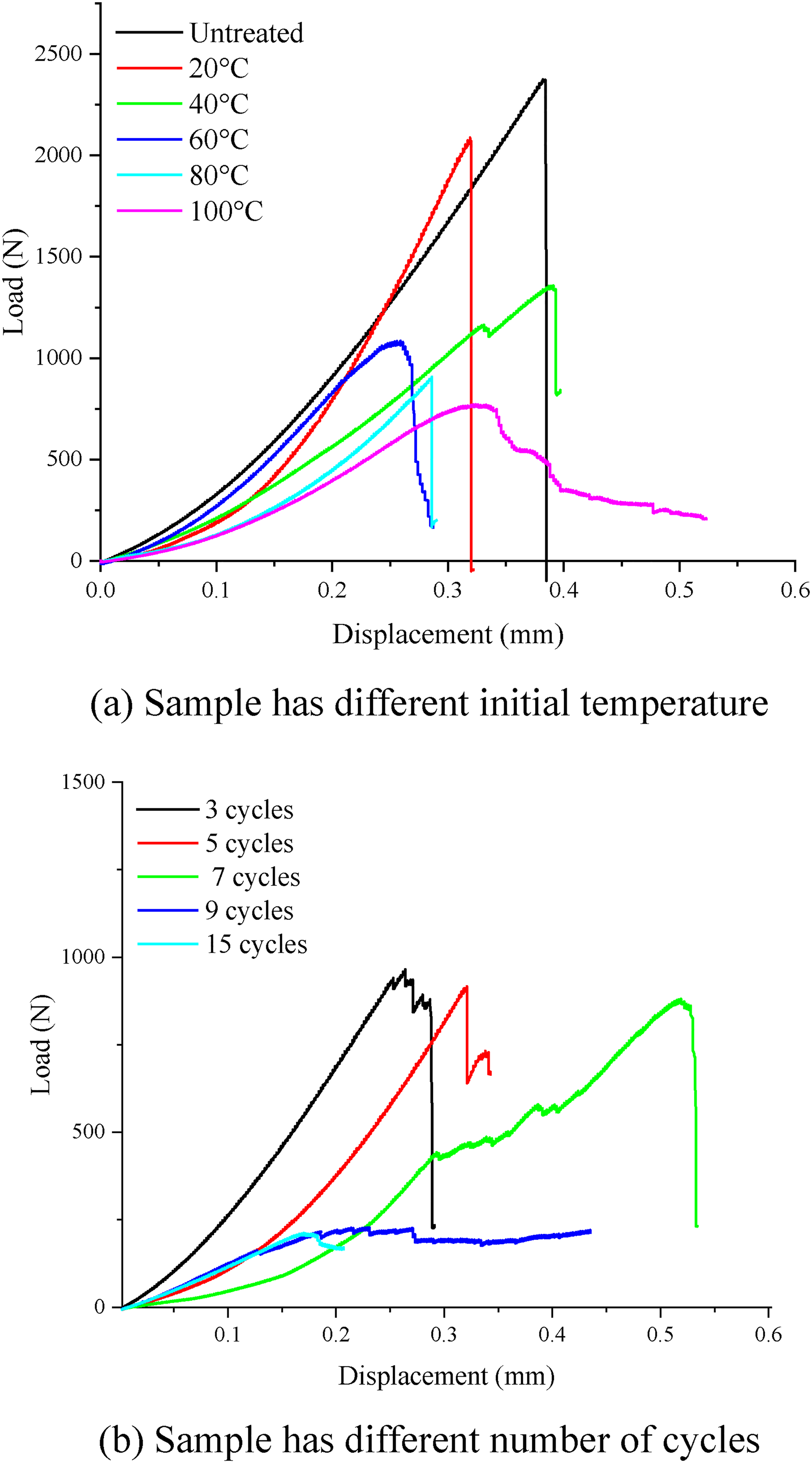
Comparison of force and displacement of samples treated with liquid nitrogen under different initial conditions. (a) Sample has different initial temperature. (b) Sample has different number of cycles.
As illustrated in the graph, a gradual reduction in peak load is observable with increasing initial temperature for the sample treated with liquid nitrogen. Furthermore, a decline in peak load is also apparent as the number of cycles increases. Notably, the peak load of the sample treated with liquid nitrogen at 20 °C experiences a substantial decrease. This implies that the damage incurred by the sample from liquid nitrogen treatment increases proportionally with both temperature and number of cycles. Additionally, the graph demonstrates that the impact of an increased number of cycles on peak load is more pronounced than that of temperature. Consequently, this infers that the endurance performance of the sample steadily decreases following treatment with liquid nitrogen, as the number of cycles increases.
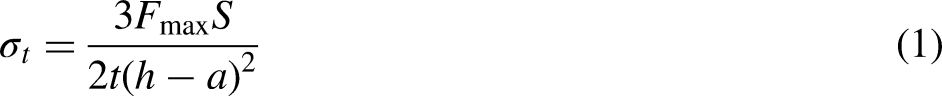
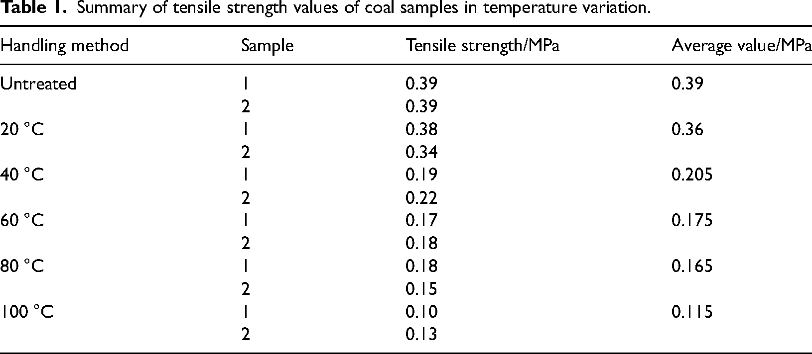
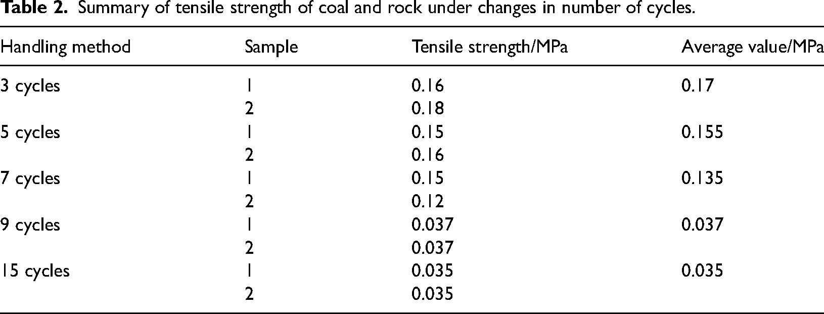
To further analyze the mechanical characteristics of rock and calculate its tensile strength, it is possible to determine the tensile strength of coal rock through an evaluation of the load-displacement curve. In order to simplify the calculation process, the following method (Wang et al., 2016; Wei et al., 2016) was adopted to calculate the tensile strength of coal rock under different treatment conditions. The obtained tensile strength values are shown in Tables 1 and 2.
Summary of tensile strength values of coal samples in temperature variation.
Summary of tensile strength of coal and rock under changes in number of cycles.
In the equation, Fmax represents the maximum load that coal rock can withstand in N; S represents the span of the specimen in m; t refers to the thickness of the specimen, given in meters (m); h represents the height of the specimen, measured in meters (m); and a denotes the length of the pre-made crack, reported in meters (m).
According to the table above, the tensile strength of coal rock decreases overall with changes in temperature and the number of liquid nitrogen cooling cycles. Additionally, the mechanical characteristics of coal rock exhibit distinct trends when tested under different temperature and cycle conditions. Coal rock exhibits a lesser degree of deformation and damage, manifesting in a comparatively minor reduction in tensile strength, when subjected to low temperatures and fewer cycles. However, when exposed to high temperatures and an increased number of cycles, the deformation and damage of coal rock become more significant, causing the decrease in tensile strength to gradually intensify.
These findings suggest that a liquid nitrogen fracturing treatment significantly affects the mechanical characteristics of coal rock, with the degree of impact contingent upon the treatment temperature and number of cycles. In practical applications, in order to ensure the physical properties and stability of coal rock, we need to develop a reasonable liquid nitrogen fracturing treatment plan based on actual conditions, and control the treatment temperature and number of cycles accordingly.
AE characteristics analysis of coal and rock
Experimental results of acoustic emission characteristics
Three methods exist for analyzing AE signals (Shahidan et al., 2013). The first method is signal parameter analysis, which utilizes parameters such as ringing count, energy, time, and amplitude to statistically reflect the fracture characteristics of rocks. Secondly, source location involves synchronously monitoring with multiple sensors and using the time difference between signal arrivals to calculate the position of the crack source. Source location can continuously determine the spatial distribution of micro-fracturing within the rock during the loading process. Finally, the study of signal characteristics involves a plethora of time-frequency information. By analyzing the dynamic characteristics of AE signals, researchers can obtain the desired information. Only when the signal reaches the detection threshold can it be detected by the probe, and then analyzed and displayed on the main host. As a result, the intensity of the AE signal waveform exhibits a shape of increasing amplitude followed by a decrease until it eventually disappears completely. Figure 6 shows a waveform of an AE signal and some of its characteristic parameters.
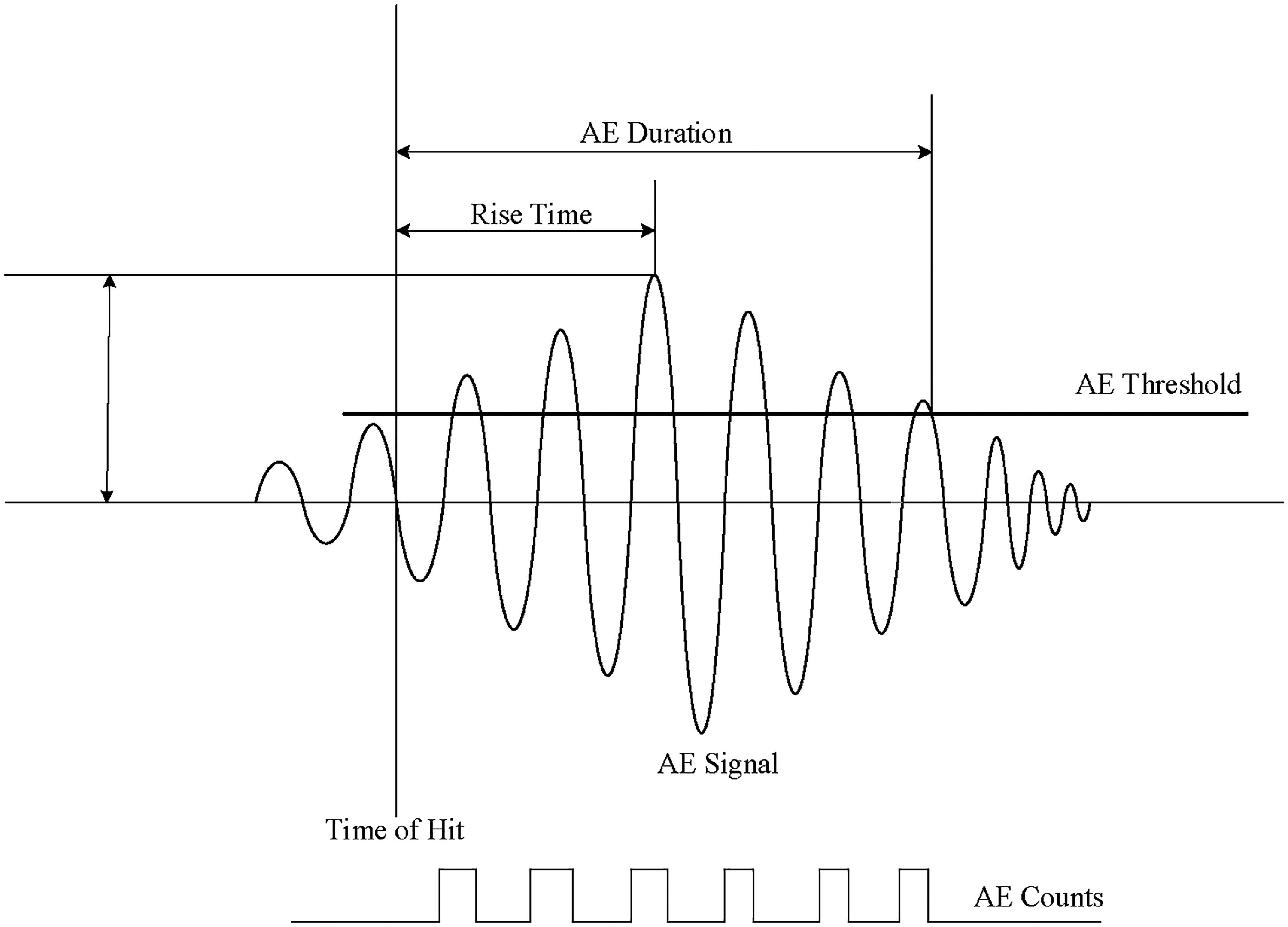
Acoustic emission waveform.
This article presents a quantitative analysis and evaluation of AE events by examining various AE parameters, including cumulative AE counts and energy, AF and RA values among others. AE counts represent the number of oscillations exceeding a threshold signal, thereby serving as an indicator of AE activity. Cumulative AE counts and energy, respectively, represent the summation of all AE counts and energy up to a designated point in time. Any signal crossing a threshold is considered an impact, reflecting the total quantity and frequency of AE activity. AF value refers to the average frequency of AE impacts above the threshold signal calculated by dividing the number of AE impacts by their duration, with units in kHz. The RA value represents the ratio of the time duration between the initial crossing of the threshold signal and the highest amplitude of the AE signal, measured in milliseconds per volt (ms/V). These parameters can help assess structural health conditions and forecast potential faults.
Based on the results of the AE testing, several sets of representative data were selected for analysis. The load-time curves of AE ring counts, cumulative ring counts, and energy are plotted in the chart shown below. The results for different cycling numbers are depicted in Figure 7.
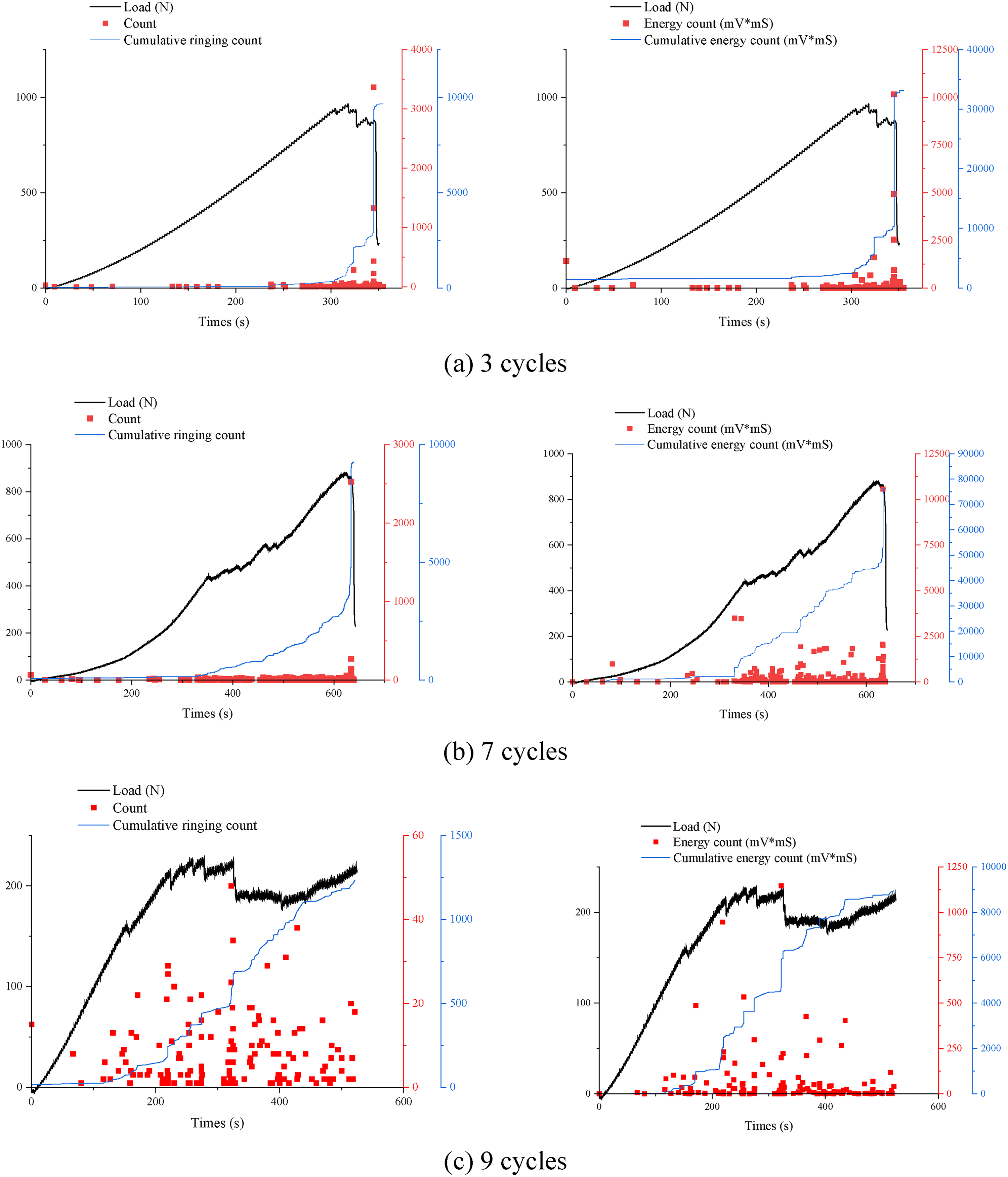
The load counting cumulative count and the load energy cumulative energy diagram of coal samples under the change of cycle times. (a) 3 cycles. (b) 7 cycles. (c) 9 cycles.
Based on the graphs, it is clear that as the cycle number increases, both ringing and energy counts decrease overall. When the load is relatively small, ringing and energy counts increase at a slower rate. However, when the load reaches its peak, ringing and energy counts tend to reach their maximum values as well. This indicates that as the cycle number and load value increase, the damage inflicted upon the coal body becomes greater.
Overall, AE activity can be divided into four distinct stages. During the first stage, characterized by the initial formation of cracks, AE activity is minimal. In the second stage, as the coal and rock mass undergoes elastic deformation, a small number of low-energy AE signals are produced, with a relatively long duration. The third stage marks the onset of inelastic deformation, during which a large number of highly concentrated AE signals are generated, and the energy of these signals gradually increases. At the point when the load reaches its apex, the energy of the accompanying AE signals also attains its highest level. Finally, during the fourth stage, which corresponds to the failure stage after the stress peak, AE activity remains active but its energy begins to decay.
Observing the ringing count graph, it is evident that with an increase in the number of liquid nitrogen freeze-thaw cycles, the ringing count of the cyclic coal increases significantly. As the number of freeze-thaw cycles continues to increase, the intensity of AE activity during the stages of rupture, plasticity, compaction, and elasticity also increases. The AE signals during the coal and rock fracture process represent the level of activity within the coal and rock, and as the number of cycles increases, damage will occur in certain areas. When a load is applied, the AE ringing count will experience a sudden increase, leading to a sharp rise of the cumulative ringing count curve. In conclusion, liquid nitrogen freeze-thaw treatment can fully demonstrate the fracturing effect of liquid nitrogen, activate the original damage potential of coal and rock, and affect the distribution of damage, ultimately influencing the characteristics of coal and rock.
From an energetic perspective, there are four distinct jumps in AE activity, corresponding respectively to 20%, 50%, 60%, and 80% of the peak load. Analysis of ringing counts and energy levels before and after liquid nitrogen treatment of coal and rock specimens reveals that, compared with untreated samples during the compaction stage, those treated with liquid nitrogen exhibit greater ringing counts and energy values, although the probability of this occurring decreases over time. During the compaction stage, AE events occur between the coal and rock specimen and the loading plate, followed by internal crack closure within the specimen resulting from applied load and subsequent AE activity. In the elastic stage, AE energy changes only slightly within a restricted range. In the rupture stage, as the applied stress increases, AE activity becomes increasingly active and continues until the coal and rock sample fails. With progressive increases in pressure, the coal and rock sample enters the failure stage after the peak load, where both load and AE activity decline steeply. Overall, the cumulative AE energy curve and load curve show parallel upward trends with distinct jumps occurring during various stages of the peak load and afterwards.
RA-AF data analysis
Prior to this study, JCMS-IIIB5706 was commonly utilized by scholars for classifying rock fissures using the AF (count/duration) and RA (duration/peak amplitude) methods (Wang et al., 2019). These methods categorize fissures into two types: tensile and shear, as illustrated in Figure 8.
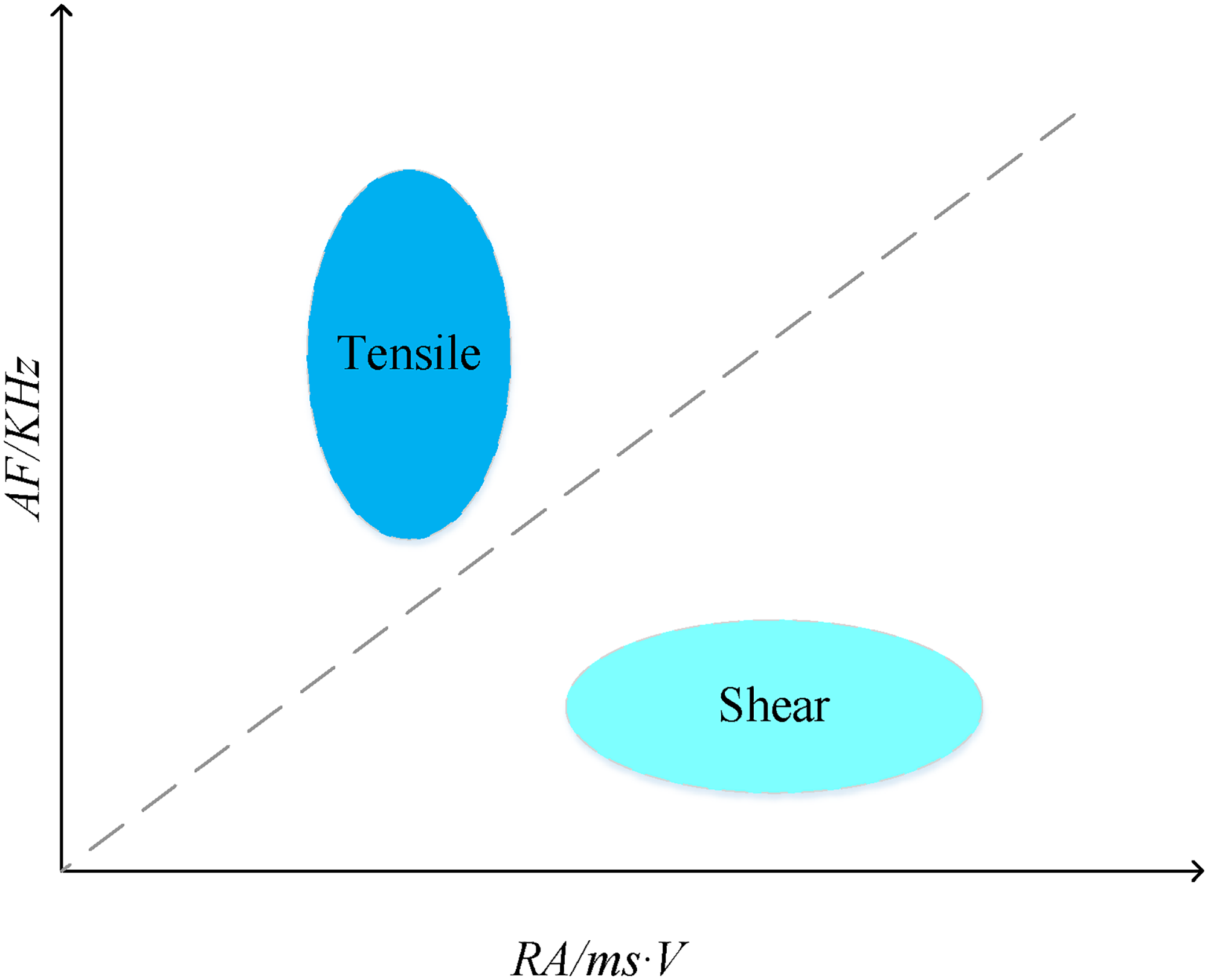
Tensile shear distribution.
Upon analysis of Figure 9, it is evident that the majority of data points are distributed above the diagonal line close to the AF axis. This implies that, with increasing initial sample temperatures after liquid nitrogen treatment, the proportion of tensile fractures in the RA-AF distribution plot significantly increases, indicating a gradual rise in the proportion of tensile failure of coal with initial temperature. Therefore, when fracturing coal using liquid nitrogen, it is advisable to raise the temperature of the coal sample as much as possible to enhance fracturing effects and minimize work-related hazards. Additionally, our analysis reveals that the effects of liquid nitrogen fracturing differ at different temperatures, with coal fracturing more effectively at lower temperatures. Under high-temperature conditions, cracks do not form as distinctly, making it difficult to guarantee effective fracturing. Consequently, liquid nitrogen fracturing experiments should be conducted within an appropriate temperature range. Considering the economic benefits and work safety aspects of practical production, it is important to develop reasonable and feasible operating plans based on actual circumstances to improve work efficiency and quality while ensuring work safety.
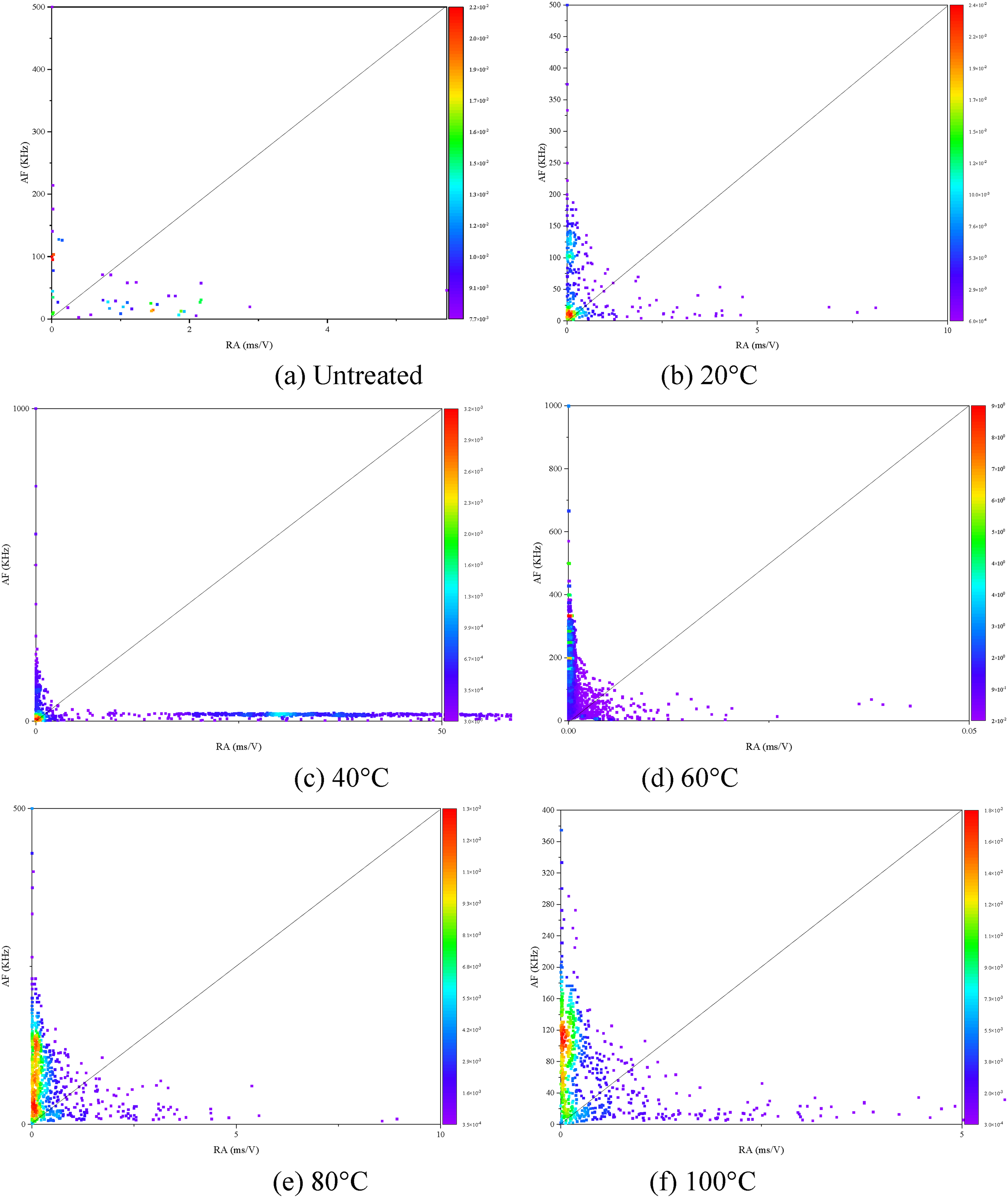
Schematic representation of RA-AF distribution under temperature change. (a) Untreated (b) 20 °C. (c) 40 °C (d) 60 °C. (e) 80 °C (f) 100 °C.
Analysis of Figure 10 shows that, with an increasing number of cycles of sample heating and liquid nitrogen cooling, the proportion of tensile fractures in the RA-AF distribution plot significantly increases. This indicates that the proportion of tensile failure of coal also increases with an increasing number of liquid nitrogen treatment cycles. Therefore, when conducting liquid nitrogen fracturing experiments, it is advisable to subject the coal samples to multiple treatments to achieve better fracturing effects. Additionally, thorough sample preparation is necessary before conducting liquid nitrogen fracturing experiments to ensure better results. For instance, impurities in the sample should be removed as much as possible, and the uniformity and integrity of the sample should be ensured. Furthermore, attention to operational details during liquid nitrogen fracturing is crucial to prevent operational errors and safety incidents.
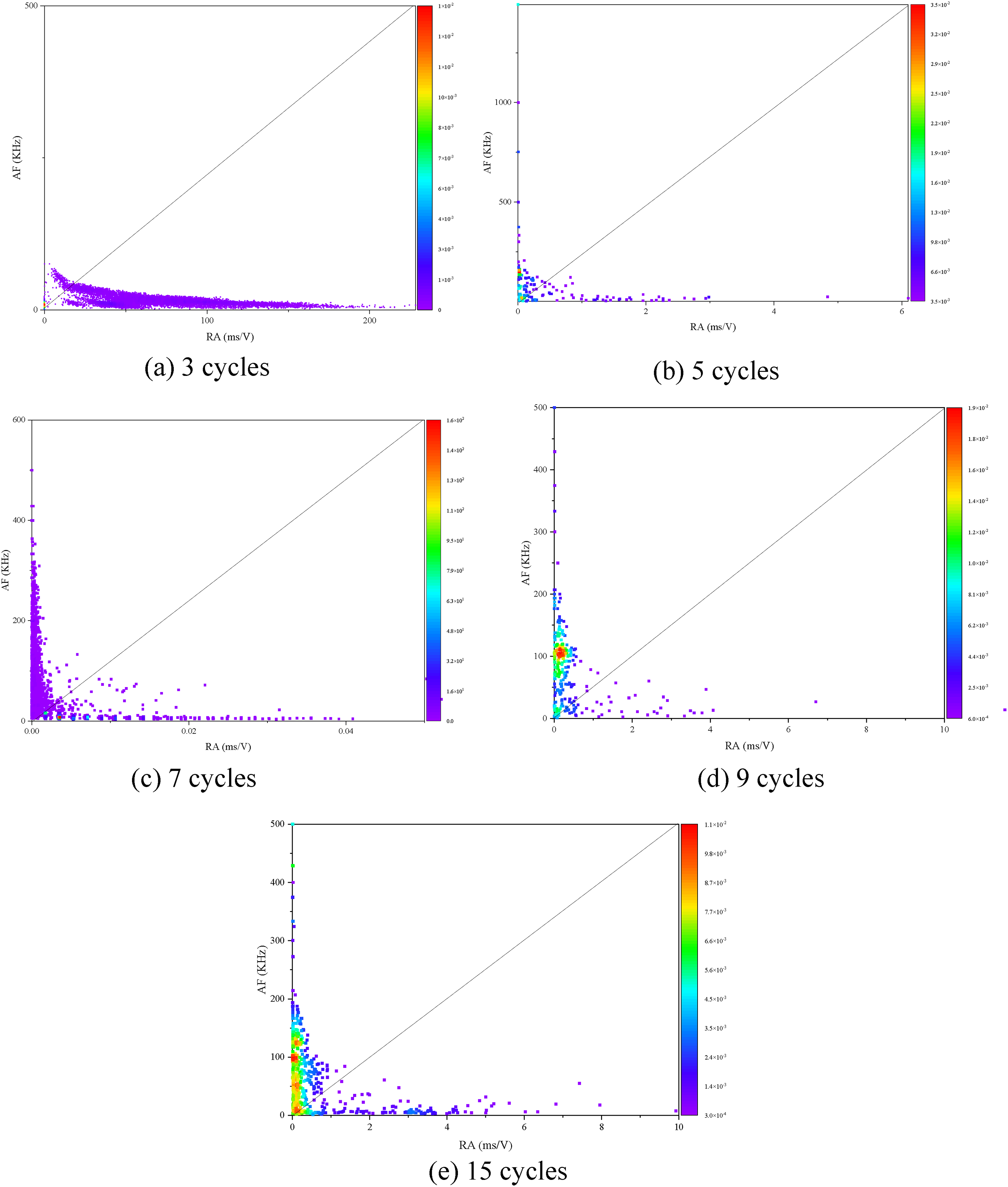
The distribution of RA-AF under the change of cycle times. (a) 3 cycles (b) 5 cycles. (c) 7 cycles (d) 9 cycles. (e) 15 cycles.
In summary, analysis of the RA-AF distribution plot provides some recommendations and measures to improve liquid nitrogen fracturing experiments. It is recommended to subject the coal samples to multiple treatments, accurately determine the fracturing temperature, and attend to operational details to achieve better fracturing effects.
Fracture surface morphology of coal sample
The cross-sectional characteristics at different temperatures
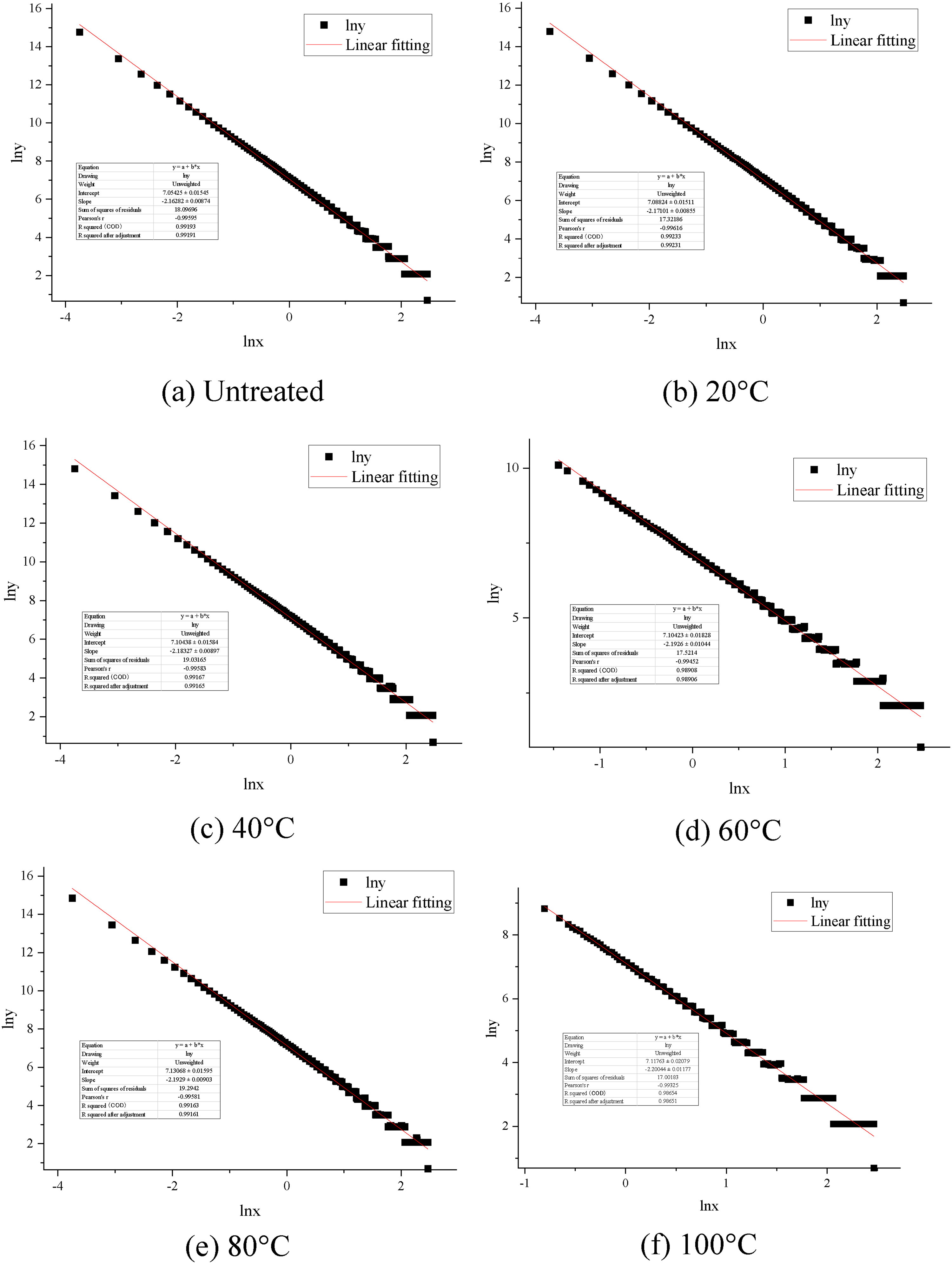
The utilization of three-dimensional morphology scanner enables a more precise and detailed analysis of the fracture surface of coal samples, capturing crucial structural information that contributes to the development of more effective mining techniques. In this paper, a three-dimensional morphology scanner was employed to scan the fracture surfaces of coal samples, and the results for a specific temperature group are presented in Figure 11. Based on the experimental data, the box dimension D was computed, allowing for the synthesis of fracture morphology and surface characteristics.
The cross-sections of granite samples at different temperatures and the corresponding fitting results. (a) Untreated. (b) 20 °C. (c) 40 °C. (d) 60 °C. (e) 80 °C. (f) 100 °C.
Based on the observations from Figure 11, distinct surface undulation features are observed on the cross-sectional surfaces of coal samples at different temperatures. The gap between the maximum peak and maximum valley varies between 3.352 mm and 15.799 mm, indicating the presence of numerous microcracks within the coal samples, resulting in a rougher fracture surface after failure. The untreated coal samples exhibit relatively flat surface undulations and fewer cracks, while the number of cracks increases and significant undulations develop after heating and liquid nitrogen treatment. Further analysis of the linear fitting reveals a fitting accuracy greater than 0.99, indicating excellent fractal characteristics of the fracture surfaces. This implies that the fracture surfaces of coal samples exhibit similar geometric patterns at different scales, aligning with the principles of fractal geometry.
A statistical analysis was performed to evaluate the fractal dimension and surface roughness of the fracture surfaces, as shown in Figure 12. The untreated samples exhibited a mean fractal dimension of 2.155. However, significant increases in fractal dimension were observed in the fracture surfaces of coal samples after heating and liquid nitrogen treatment, with a value of 2.20 achieved when the samples were treated with liquid nitrogen and heated to 100 °C. The increase in fractal dimension corresponded to an increase in surface roughness, indicating an increase in the surface area of contact between the crack network and the matrix. This effect can enhance gas exchange efficiency and improve permeability of the coal sample, which in turn has positive implications for gas extraction. The untreated samples exhibited lower surface roughness, with a mean value of only 521.5 μm. However, as temperature increased, the roughness of the coal samples significantly increased, and both surface roughness and fractal dimension were observed to vary proportionally with temperature. During the three-point bending test, the microcracks induced by liquid nitrogen had an impact on the fracture evolution of the coal samples. This effect resulted in a more disordered and random process of crack propagation inside the coal samples, leading to more complex features in the fracture surface. Accordingly, the fractal dimension, surface roughness, and height differences of the fracture surface were all observed to increase. Therefore, significant changes in surface roughness were observed in the fracture behavior of the coal samples after heating and liquid nitrogen treatment, which were closely related to temperature. The existence of microcracks induced by liquid nitrogen treatment significantly altered the characteristics of the fracture surface of coal samples, further affecting the fracture evolution process and morphological features of the fracture surface.
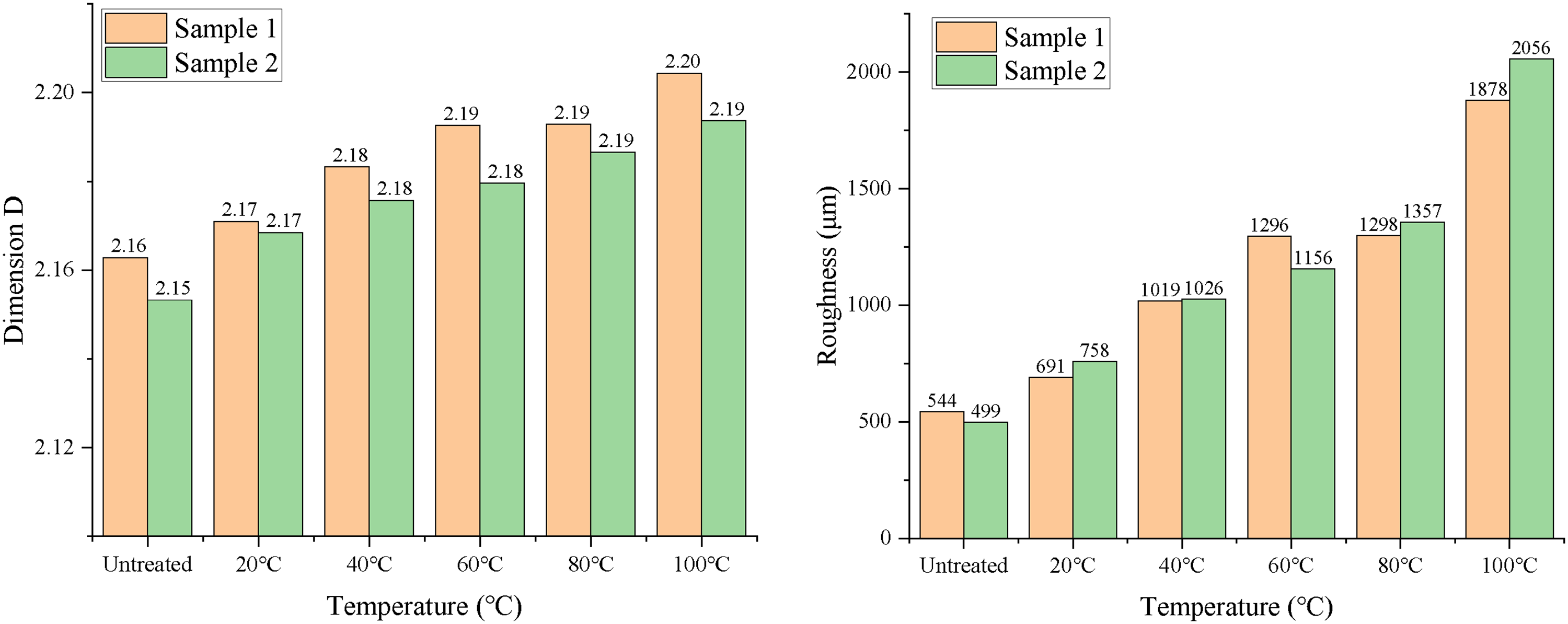
Evolution law of characteristic parameters of fault surface.
The cross-sectional characteristics at different cycles
A detailed analysis was conducted on the surface characteristics of the cross-sections of the cyclic group, and the results are shown in Figure 13. Similar to the temperature group results, the cross-sections of the coal samples also exhibit different undulation features. In this cyclic group, the range between the maximum peak and the maximum valley is found to be between 4.912 mm and 11.784 mm, indicating that with an increase in the number of cycles, there are more microcracks within the coal sample. These microcracks significantly affect the morphology of the fracture surfaces of the coal samples after failure. Based on observations and analysis, it can be concluded that the undulation features of the cross-sections exhibit distinct fractal properties, including numerous local peaks and valleys. The existence of these fractal properties indicates the presence of complex and diverse microstructures within the coal samples, which in turn contribute to the complexity and unpredictability of the fracture evolution process. The results demonstrate that in the cyclic group experiments, as the number of cycles increases, the microstructures within the coal samples become increasingly complex, leading to significant variations in the undulation features of their cross-sections. This further emphasizes the significant influence of microstructural factors on the fracture evolution process and the morphology of the fracture surfaces of the coal samples.
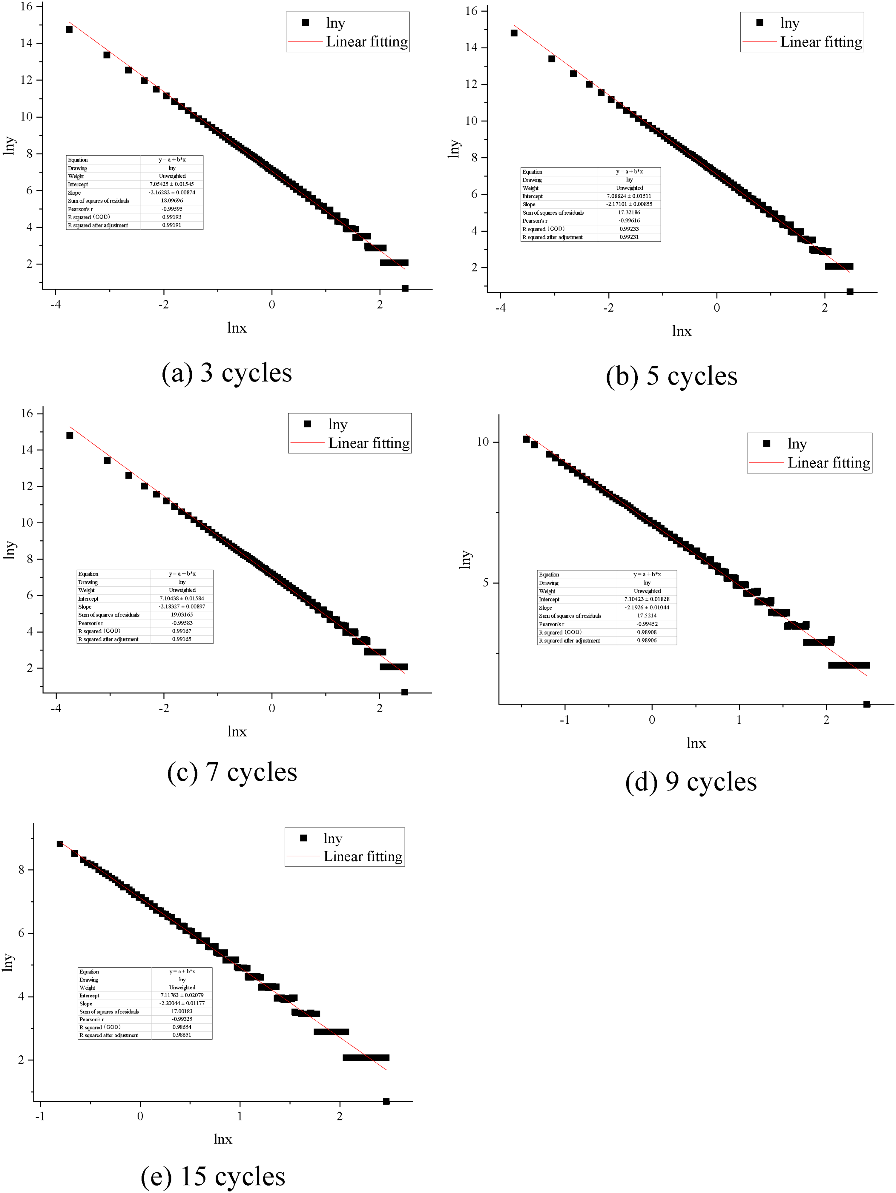
The cross-sections of granite samples at different cycles and the corresponding fitting results. (a) 3 cycles. (b) 5 cycles. (c) 7 cycles. (d) 9 cycles. (e) 15 cycles.
By analyzing the evolution law of fractal dimension and roughness, further research was conducted on the surface characteristics of coal rock cross-sections, as illustrated in Figure 14. At low numbers of cycles, the mean fractal dimension approaches 2.16. However, when the number of cycles increases to 15, the average fractal dimension also increases to 2.205. This indicates that the undulation of the fracture surface gradually increases, resulting in an increase in the contact area between the crack networks. Specifically, with an increase in the number of cycles, more undulation features appear on the cross-section surface of the coal samples. The crack network plays an important role in the fracture process, and the undulation of the fracture surface exhibits a critical influence on the contact area of the crack networks. As the undulation of the fracture surface increases, not only does the contact area between the cracks increase, but more microstructural features also emerge, thereby increasing the roughness of the fracture surface. It was observed that roughness continuously increased with an increase in the number of cycles. Therefore, significant changes in roughness were observed in the fracture behavior of coal samples treated with liquid nitrogen. The microcracks caused by the liquid nitrogen treatment resulted in significant changes in the surface characteristics of the coal samples, further affecting the fracture evolution process and the morphology of the fracture surfaces.
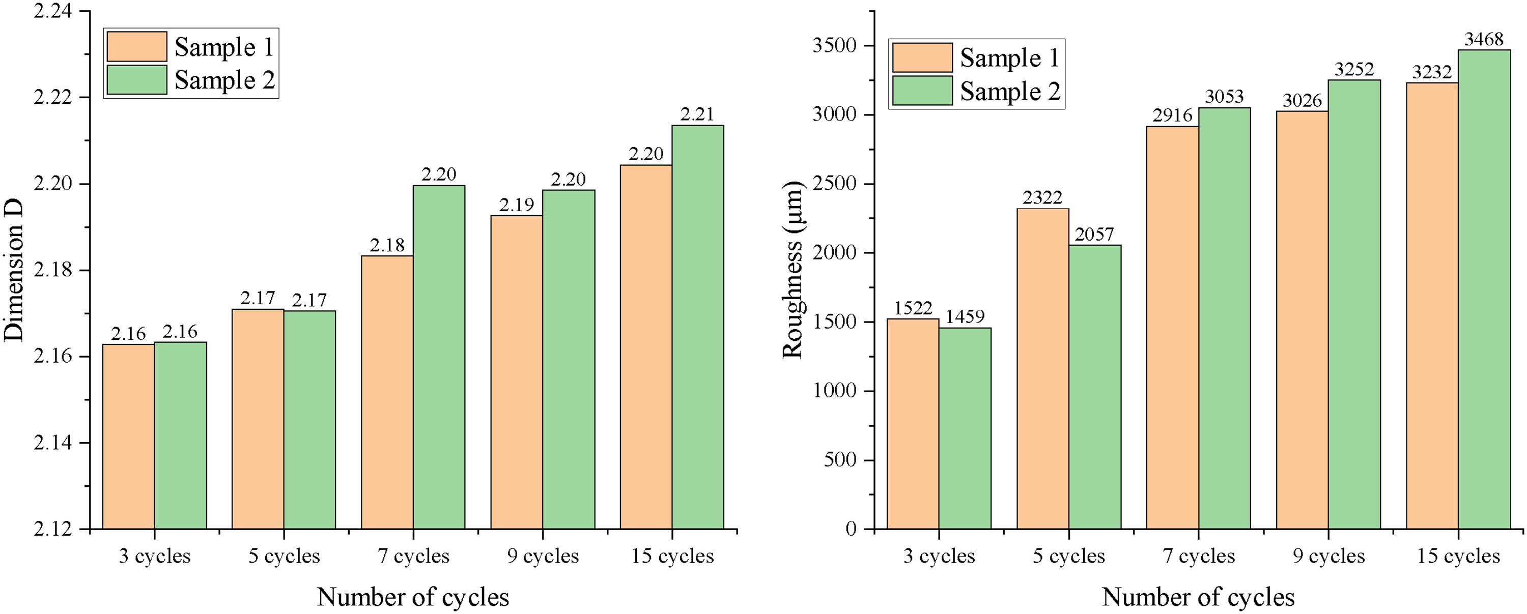
Evolution law of characteristic parameters of fault surface.
Conclusion
The use of liquid nitrogen fracturing technology offers an effective means of extracting CBM, while also avoiding water resource waste and environmental pollution caused by hydraulic fracturing. Furthermore, this technology provides a more efficient method of extracting CBM. In order to maximize the economic gains from liquid nitrogen fracturing technology, this investigation explored the alterations in the mechanical characteristics and AE parameters of coal samples treated with liquid nitrogen. Through indoor three-point bending tests and AE experiments, the following conclusions were reached:
The effectiveness of liquid nitrogen fracturing is influenced by the environment, and different environmental conditions have varying effects. As temperature increases, the peak load of coal and rock gradually decreases. Similarly, at the same temperature, an increasing number of cycles also leads to a continuous decrease in peak load. These results suggest that temperature and the number of cycles have a significant impact on the effectiveness of liquid nitrogen fracturing. Analysis of the cumulative AE count and cumulative AE energy curves demonstrate that augmented liquid nitrogen freeze-thaw cycles and temperature contribute to heightened AE activity throughout the four-load loading stages of coal and rock compaction, elasticity, plasticity, and fracture. Following the application of a load, the AE ringing count experiences a sharp increase, leading to a surge in the cumulative ringing count curve. Both liquid nitrogen freeze-thaw cycle and high-temperature treatment effectively enhance the fracturing effect of liquid nitrogen by stimulating the original damage potential of coal and rock, thereby influencing their mechanical properties. Comparative analysis of the RA-AF density distribution maps under different environmental conditions reveals that during the gradual loading process of coal and rock samples, crack initiation and extension leading to failure mainly involve tensile cracks, while the development, extension, and failure of shear fractures play a secondary role. However, as the number of cycles and temperature escalates, the share of the secondary shear effect gradually enlarges. The internal structure of coal rock can be effectively modified through two methods: liquid nitrogen cycling treatment and liquid nitrogen treatment followed by heating. During the mechanical experimentation process, coal rock undergoes continuous damage, with its surface roughness and fractal dimension increasing proportionally with the number of cycles and temperature. Hence, in practical engineering applications, suitable treatment methods can be chosen based on specific operational requirements for the extraction or reinforcement of coal rock.
Footnotes
Declaration of conflicting interests
The author(s) declared no potential conflicts of interest with respect to the research, authorship, and/or publication of this article.
Funding
The author(s) received no financial support for the research, authorship, and/or publication of this article.