
Abstract
Liquid nitrogen is a type of super-cryogenic fluid, which can cause the reservoir temperature to decrease significantly and thereby induce formation rock damage and cracking when it is injected into the wellbore as fracturing fluid. An experimental set-up was designed to monitor the acoustic emission signals of coal during its contact with cryogenic liquid nitrogen. Ultrasonic and tensile strength tests were then performed to investigate the effect of liquid nitrogen cooling on coal cracking and the changes in mechanical properties thereof. The results showed that acoustic emission phenomena occurred immediately as the coal sample came into contact with liquid nitrogen. This indicated that evident damage and cracking were induced by liquid nitrogen cooling. During liquid nitrogen injection, the ring-down count rate was high, and the cumulative ring-down counts also increased rapidly. Both the ring-down count rate and the cumulative ring-down counts during liquid nitrogen injection were much greater than those in the post-injection period. Liquid nitrogen cooling caused the micro-fissures inside the coal to expand, leading to a decrease in wave velocity and the deterioration in mechanical strength. The wave velocity, which was measured as soon as the sample was removed from the liquid nitrogen (i.e. the wave velocity was recorded in the cooling state), decreased by 14.46% on average. As the cryogenic samples recovered to room temperature, this value increased to 18.69%. In tensile strength tests, the tensile strengths of samples in cooling and cool-treated states were (on average) 17.39 and 31.43% less than those in initial state. These indicated that both during the cooling and heating processes, damage and cracking were generated within these coal samples, resulting in the acoustic emission phenomenon as well as the decrease in wave velocity and tensile strength.
Introduction
Natural gas is a significant fossil energy, which has played an important role in national industry and economy. As Rui et al. (2017) stated that natural gas supplies have accounted for about one-fourth of all energy around the word. Thus, to further improve the natural gas supplies, the unconventional resources, such as coalbed methane (CBM), have attracted increasing attention (Vedachalam et al., 2015). CBM is a type of clean, high-quality energy, which can help to reduce the issue of greenhouse gas emissions (Salmachi and Karacan, 2017). However, the CBM is mainly stored in adsorption form within the coal matrix and the gas production is strongly dominated by the natural fractures (e.g. cleats). It is because that these natural fractures can provide high permeability pathways for the gas flowing from coal matrix to wellbore (Clarkson and Salmachi, 2017). Yarmohammadtooski et al. (2017) stated that the cleat systems in CBM reservoirs are critical to evaluate formation quality and make the field development plans. Salmachi et al. (2016) also pointed out that the productivity of coalbed can be predicted by interpreting the cleat systems and the open natural fractures based on borehole image logs. Unfortunately, because of strong adsorption characteristics of coal, the simulation methods, such as hydraulic fracturing, have to be implemented to maintain CBM production at an economic rate (Aguilera et al., 2014; Salmachi and Yarmohammadtooski, 2015).
As the problems of reservoir damage, environmental pollution, and water consumption that the hydraulic fracturing has confront with become more severe (Anderson et al., 2010; Bahrami et al., 2012; Zhang and Yang, 2015), waterless fracturing technologies have attracted extensive attention and become an important direction for unconventional natural gas development (Chen et al., 2015; Hou et al., 2017; Xie et al., 2016). Liquid nitrogen is a commonly used fluid in petroleum engineering and has been successfully applied to well fracturing operations (Grundmann et al., 1998; McDaniel et al., 1997). Moreover, liquid nitrogen fracturing is also expected to play an important role in the development of unconventional reservoirs, including CBM (Wang et al., 2016). Liquid nitrogen is colourless, tasteless, and presents excellent compatibility with formation fluids. Thus, it can prevent reservoir damage, reduce water consumption, and lower the demands imposed upon wastewater treatment systems when used as a fracturing fluid. In this case, liquid nitrogen fracturing has attracted global attention (Alqatahni et al., 2016; Cai et al., 2016; Cha et al., 2014). Besides, liquid nitrogen has an extremely low cryogenic temperature (−195.56 to −180.44°C), which can decrease the reservoir temperature and improve the stimulation reservoir volume (Cai et al., 2014a). Additionally, it has been proved that the thermal treatment was feasible to increase shale gas and CBM production (Lee et al., 2017; Salmachi and Haghighi, 2012). In a word, liquid nitrogen fracturing has many advantages in protecting reservoirs, saving water, and enhancing the stimulation effect.
Compared to conventional fracturing technologies, the super-cryogenic characteristic of liquid nitrogen is the key point demarcating liquid nitrogen fracturing. The cryogenic cracking effect of liquid nitrogen on coal has been studied by many researchers. McDaniel et al. (1997) indicated that cubical debris desquamated from coal samples upon contact with liquid nitrogen; cracking sounds were also heard when the coal samples were submerged in, and removed from, liquid nitrogen. Ren et al. (2013) investigated the change in the ultrasonic wave velocity and amplitude of coal attributed to liquid nitrogen cooling and discovered that the wave velocity and amplitude decrease. Cai et al. (2014b, 2015) performed nuclear magnetic resonance, acoustic emission (AE), and uniaxial compression tests and found that liquid nitrogen cooling could promote the expansion of micropores and improves the pore structure connectivity of a coal, consequently leading to the increase in permeability and decrease in strength. Zhang et al. (2015) indicated that the coal matrix exhibited shrinkage deformation due to liquid nitrogen cooling, which resulted in the propagation of micro-cracks and the improvement of the permeability thereof. Li et al. (2016) investigated the effect of freeze–thaw cycling with liquid nitrogen on coal micro-cracks. Their results showed that the micro-crack width increased with the growth of the temperature difference and water saturation. Zhai et al. (2016) investigated the pore structure evolution characteristics of coal after freezing with cyclic liquid nitrogen injection. They found that liquid nitrogen freeze–thaw cycles can induce damage to the pore structure and enhance coal permeability. Both the effective and total porosities of coal increase with the growth in the number of freeze–thaw cycles and freezing time. Besides, large pores that can connect with the fracture network are also easily produced by increasing the number of freeze–thaw cycles. Qin et al. (2016) performed laboratory tests to analyse the effect of cyclic liquid nitrogen freezing on the mechanical properties of coal. Their results indicated that liquid nitrogen freezing can cause the extension of micro-cracks and significantly decrease the strength, elastic moduli, and wave velocity of coal samples.
These previous studies indicate that liquid nitrogen can assist in coal cracking, promote the propagation of micro-cracks (micropores), and improve the connectivity of the coal rock pore structure. These effects can enhance the fracturing performance of CBM. The aforementioned research is mainly focused on the cryogenic cracking of liquid nitrogen on coal, namely the changes in microstructure or mechanical properties after the coal is cooled with liquid nitrogen; however, few investigations have paid attention to the damage and cracking during the time in which coal made contact with the liquid nitrogen. During liquid nitrogen fracturing, the reservoir is always in contact with the working fluid. The coal is fractured due to the coupling effect of liquid nitrogen cryogenic temperature and high pressure. The cryogenic cracking effect of liquid nitrogen on coal exists during the entire fracturing process, which can affect the formation and shape of fractures. Therefore, investigating the coal cracking characteristics and the change in mechanical properties upon contact with liquid nitrogen are crucial to revealing the cryogenic effect of liquid nitrogen on coal in real time.
An experimental set-up was designed to monitor the AE signals when liquid nitrogen was injected into a coal sample. Based on the AE parameters, the coal cracking characteristics upon contact with liquid nitrogen were investigated. Then, ultrasonic and tensile strength tests were performed on coal samples in initial, cooling, and cool-treated states (i.e. the cryogenic samples had recovered to room temperature), respectively. The results could provide guidance to those seeking to uncover the mechanisms of coal cracking during liquid nitrogen fracturing.
Materials and methods
Sample preparation
For rock mechanic experiments, the sample properties are really important. In our work, we mainly focused on the cracking effect of coal due to liquid nitrogen cooling and the influence of cryogenic cracking on coal mechanical properties. In this paper, the high-rank coals were collected from Ordos in Inner Mongolia Autonomous Region, China. In order to ensure the mechanical properties of coal samples were as similar as possible, the samples were taken from same large coal block. To characterize the mechanical properties of coals at length, preliminary tests were performed on some samples to measure the porosity, density, permeability, and compressive strength. The results were listed in Table 1.
The results of partial mechanical property tests on coals.

For different tests, the coal samples were cut to different shapes. In the AE test, the coal sample was formed into a cube with a central hole (see Figure 1). The size of the coal sample employed in the experiment was 200 mm × 200 mm × 200 mm, whereas the diameter and depth of the central hole were 100 and 150 mm, respectively. As shown in Figure 2, a sealing device was established on the central hole. The sealing device had two steel pipes: one to inject liquid nitrogen, the other to discharge liquid nitrogen or nitrogen gas. The rock sample and hole-sealing device were cemented into a 300 mm × 300 mm × 300 mm cube as shown in Figure 2. After the cement had gained sufficient strength, AE probes were established on the surface of the cement block. During the test, liquid nitrogen was injected into the central hole in the coal sample, and the AE signal induced by coal cracking was recorded through probes. In this work, two samples were prepared and labelled as AE-1# and AE-2#.
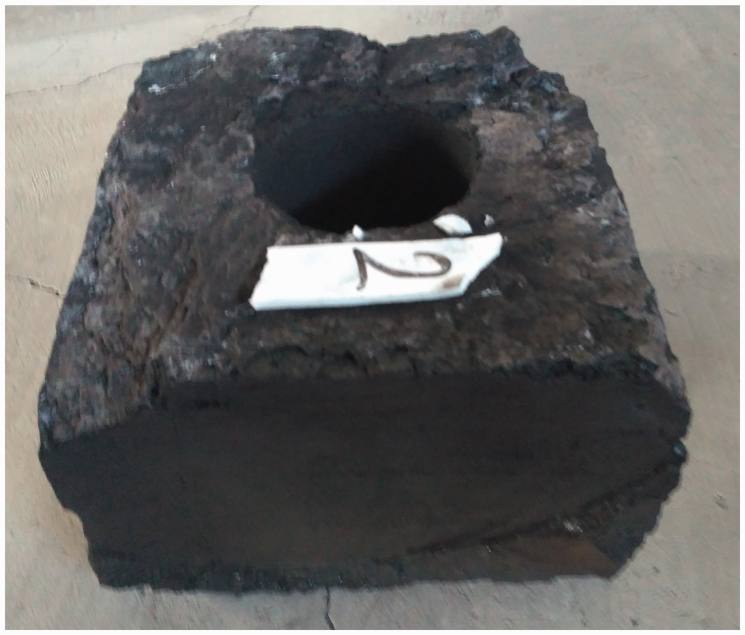
Photograph of a coal sample used in AE tests. The coal block was drilled a hole in the central position.
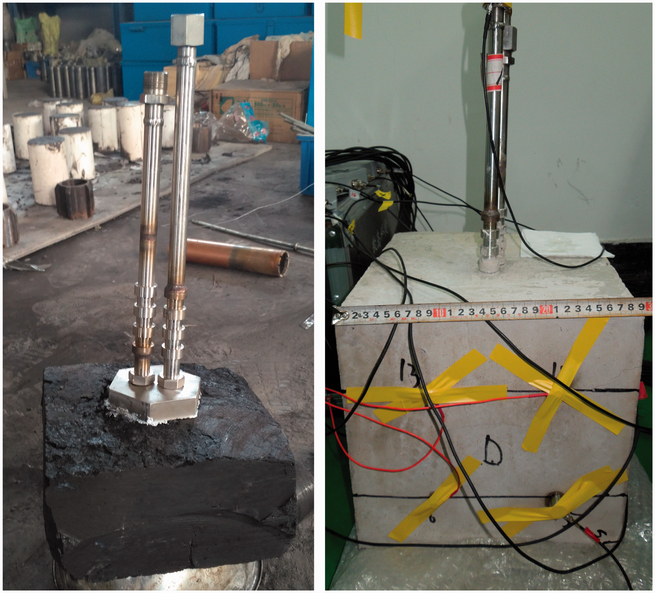
Coal sample for AE tests. Left: the bare coal with a steel hole-sealing device. Right: the coal and steel hole-sealing device were covered with the cement. The hole-sealing device was a steel apparatus with one disc base and two pipes.
For the ultrasonic tests, the samples were processed into cylinders with a diameter of 25 mm and a length of 50 mm. Four samples of regular shape and similar densities were selected and labelled U-1#, U-2#, U-3#, and U-4#. For the tensile strength tests, the samples were processed into cylinders. The diameter and length of each sample were 50 and 25 mm, respectively. Finally, nine samples were selected for tensile strength testing. These samples were divided into three groups (Groups T1, T2, and T3) and each group consisted of three samples. To distinguish them clearly, all samples for the tensile strength tests were labelled using the format ‘X-Y#’, where the ‘X’ represented the group and the ‘Y’ represented the sample number. For example, the samples in Group T1 were labelled T1–1#, T1–2#, and T1–3#.
Experimental methods
The experimental work consisted of three stages: AE testing, ultrasonic testing, and tensile strength testing. The purpose of the AE test was to measure the damage and cracking effect when the coal was in contact with the cryogenic liquid nitrogen. Once the liquid nitrogen was injected into the hole of the sample, significant thermal stress was generated around the central hole. In this case, the coal would be cracked, and the cracking signal could be monitored by the AE probes. In the ultrasonic test, the wave velocity of the same coal sample was measured in initial, cooling, and cool-treated states, respectively. For the tensile strength test, the samples in Group T1 were tested in their initial state, the samples in Group T2 were tested in the cooling state, and the samples in Group T3 were tested in the cool-treated state. The experimental steps were as follows:
(1) AE tests were performed on samples AE-1# and AE-2#, and the AE signals were recorded during the liquid nitrogen injection and post-injection stages. For sample AE-1#, the sample was placed in liquid nitrogen for 500 s and then allowed to warm up for the same time. For sample AE-2#, the duration of liquid nitrogen injection and post-injection periods were extended to 850 s. The cryogenic cracking effect of liquid nitrogen on coal was evaluated according to the AE signal parameters under different experimental conditions.
(2) Ultrasonic tests were conducted on samples U-1#, U-2#, U-3#, and U-4# to determine their initial wave velocities. Then these samples were cooled with liquid nitrogen. Once the samples were removed from the liquid nitrogen, ultrasonic tests were performed immediately to confirm the wave velocities of samples in the cooling state. As the cryogenic samples recovered to room temperature (about 25.0°C), the ultrasonic tests were performed again to acquire the wave velocities in the cool-treated state. In this way, the effect of liquid nitrogen on the wave velocity in these coal samples could be analysed.
(3) Tensile strength tests were performed on all samples of Groups T1, T2, and T3 to measure their tensile strength. In this test, the electric hydraulic servo-valve control system of MTS 815.02 (see Figure 3) at the State Key Laboratory for Geomechanics and Deep Underground Engineering (CUMT) was employed to apply load. As the samples used in tensile strength tests were processed into the disk shape, the Brazil disk split test was conducted to acquire the tensile strength of each sample. To analyse the effect of liquid nitrogen cooling on coal tensile strength, the tensile tests were performed as follows: First, the Brazil disk split tests were performed on the samples in Group T1 (i.e. T1–1#, T1–2#, and T1–3#). In this group, the samples were tested in the initial state and the original tensile strength could be measured. Second, the samples in Group T2 (i.e. T2–1#, T2–2#, and T2–3#) were submerged in liquid nitrogen to allow sufficient cooling and then the Brazil disk split tests were immediately conducted as these samples were removed from the liquid nitrogen. Third, the samples in Group T3 (i.e. T3–1#, T3–2#, and T3–3#) were also submerged in liquid nitrogen. However, the Brazil disk split tests were performed as these samples recovered to room temperature (about 25.0°C). During testing, the load was applied in the form of displacement and the load rate was about 0.03 mm/min.
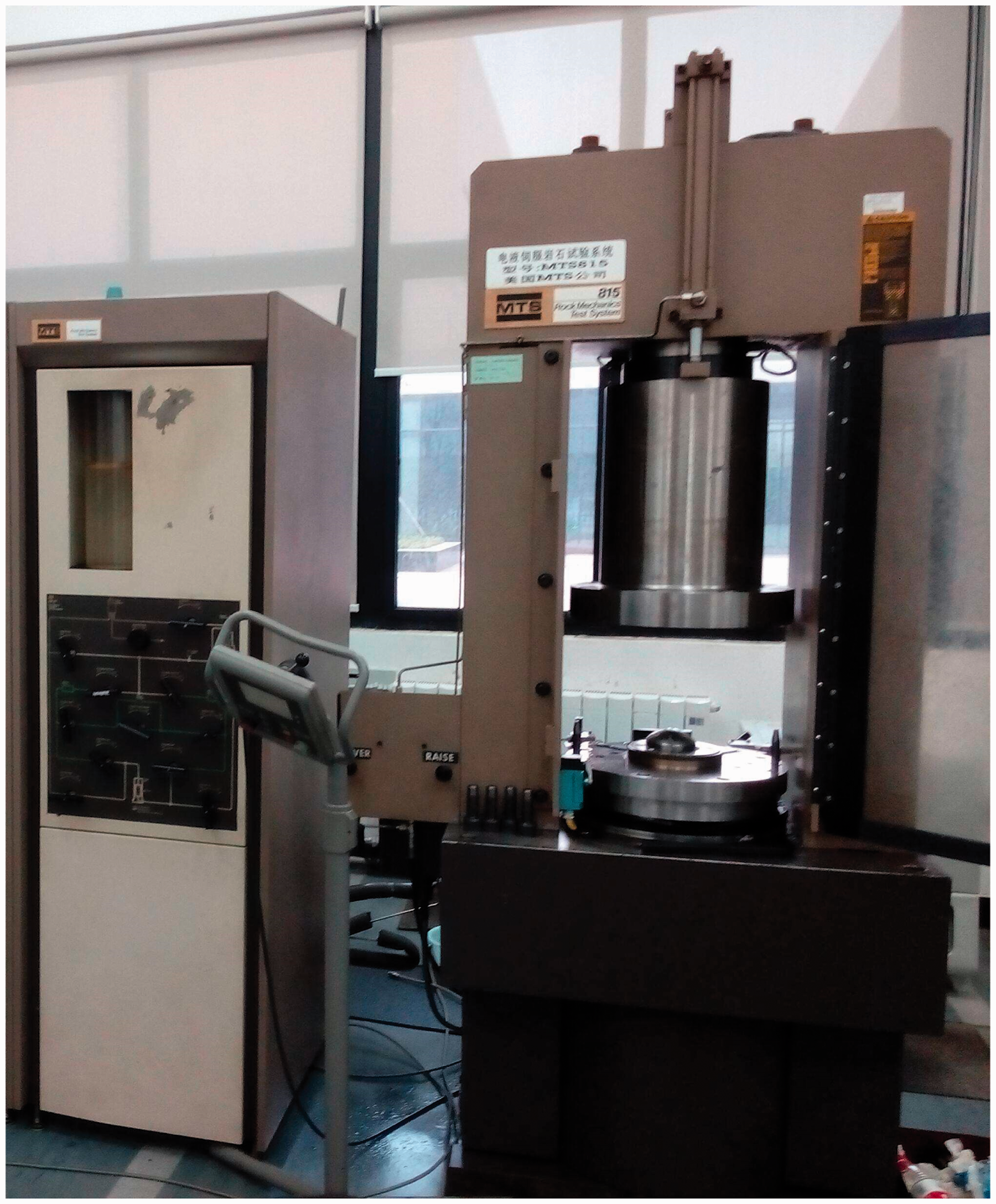
The electric hydraulic servo-valve control system of MTS 815.02.
A liquid nitrogen container, manual liquid nitrogen pump, steel pipe, DS5 AE detector (Figures 4 and 5), electric hydraulic servo-valve control system of MTS 815.02, and an M-8A non-metal ultrasonic tester were employed in the experiments. The DS5 AE detector was designed and produced by Beijing Softland Times Scientific & Technology Co. Ltd. The sampling frequency of this equipment is 50 kHz. It can continuously record the waveform for 11.6 h. The diameter and height of the AE sensors were 8 and 7 mm, respectively, and their bandwidths are 100–900 kHz. The preamplifiers of the AE detector have three different signal gains of 20, 40, and 60 dB (in this study, a signal gain of 40 dB was used). The manual liquid nitrogen pump can extract liquid nitrogen from the container and then transport it into the central hole of the rock sample. The operating principle of the manual liquid nitrogen pump is that the pressure inside the container increases when the pressure boosting ball at the top of the pump is pressed. Liquid nitrogen can flow out as the pressure increases to 0.01–0.04 MPa. The flow rate of liquid nitrogen in the experiment can be up to 4 l/min.

Schematic of the experimental equipment used in AE tests. This equipment consisted of liquid nitrogen container (with manual liquid nitrogen pump), liquid nitrogen injection pipe, AE tester, and outflow pipe. AE: acoustic emission.
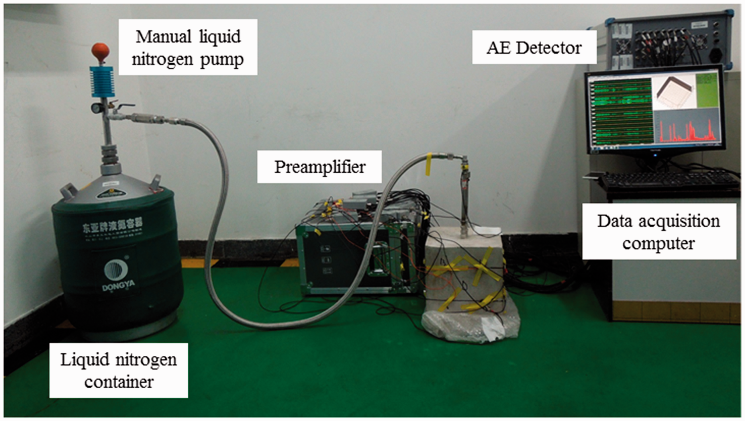
Photograph of the experimental equipment used in AE tests. AE: acoustic emission.
Experimental results and analysis
AE characteristics of coal during liquid nitrogen cooling
Before performing the AE characteristic analysis, the temperature distributions in the rock samples were simulated using a computational fluid dynamics method. As shown in Figure 6, a three-dimensional geometric model mainly consisting of two regions (a solid region and a fluid region) was built. The solid region comprised cement, coal with a central hole, and steel pipe wall; the fluid region was composed of a central hole and the internal space of the steel pipe. The size of the geometric model was set according to the experimental sample dimensions (Figures 1 and 2). During the experiment, liquid nitrogen was pumped into the rock sample through the injection pipe and then flow out through the outflow pipe. Thus, the inlet of the injection pipe was set as the mass flow inlet boundary condition, and the outlet of the outflow pipe was set as the pressure outflow boundary condition. As the rock sample made contact with the atmosphere during the experiment, the cement surfaces were set with convective heat transfer boundary conditions, and the ambient air temperature was set to 300 K. The related thermo-physical parameters of the steel pipe, coal, and cement are as listed in Table 2.
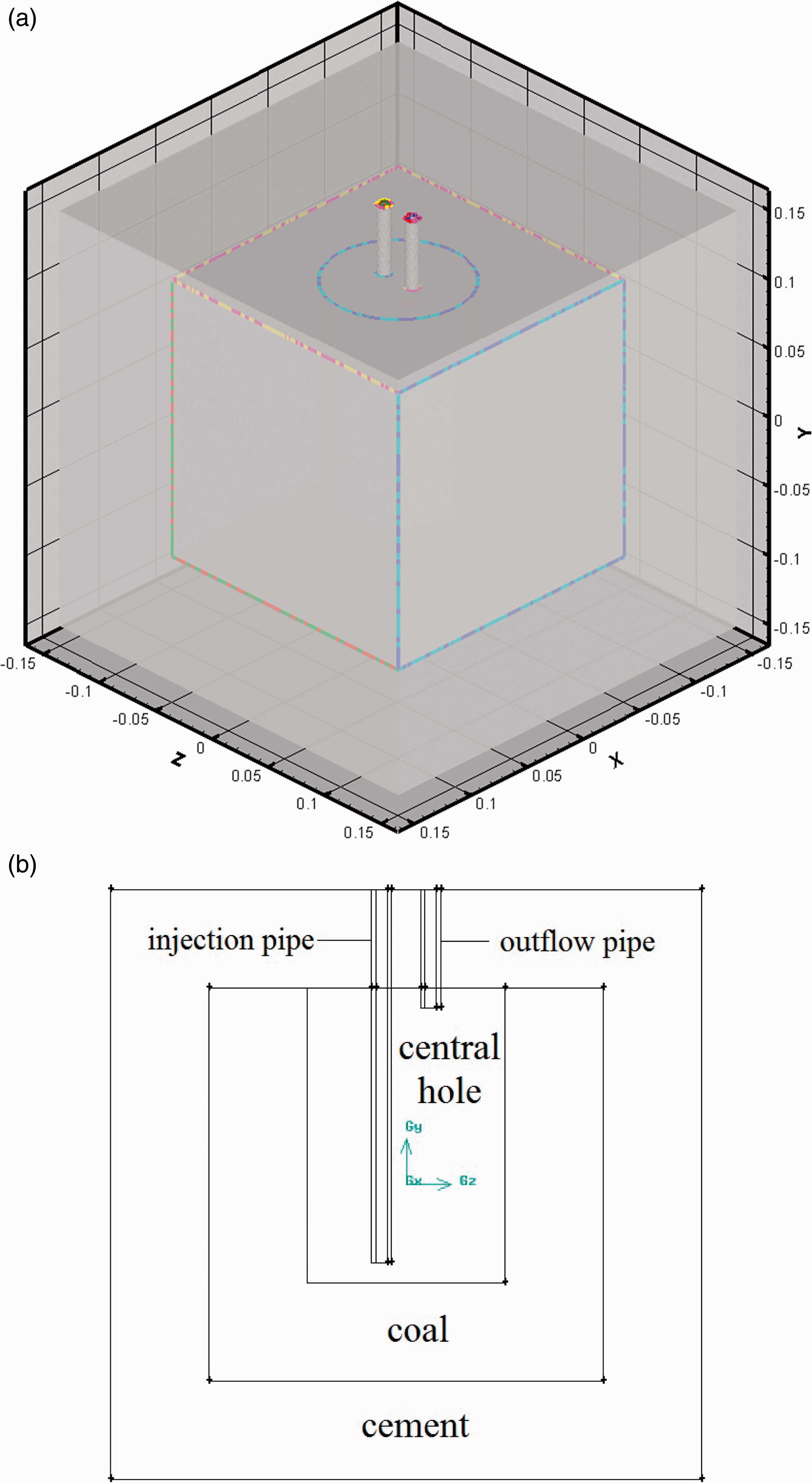
Geometric model for temperature field of sample during liquid nitrogen injection. The model was established according to experimental size to acquire the temperature data at different experimental stages. (a) Three-dimensional model (unit: m) and (b) slice in the YZ plane (X = 0).
Thermo-physical parameters of the sample materials.
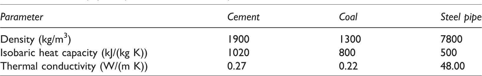
Figure 7 shows the temperature distributions of the slice in the YZ plane (X = 0) when the liquid nitrogen had been injected into the sample for 850 s. During the simulation, the mass flow rate of liquid nitrogen was set to 0.02 kg/s, and the pressure on the outlet boundary was set to atmospheric pressure. As shown in this figure, even though the sample was injected into liquid nitrogen for 850 s, the cement part around the coal is still kept at the relatively high temperature. Figure 7 also shows that the cooling region was mainly generated in the coal sample. This indicated that during the liquid nitrogen cooling process, the AE signals were mainly produced from the coal cracking. In this case, the AE signals monitored by the sensors on the surfaces of rock sample could be used to analyse the damage and cracking characteristics of coal.
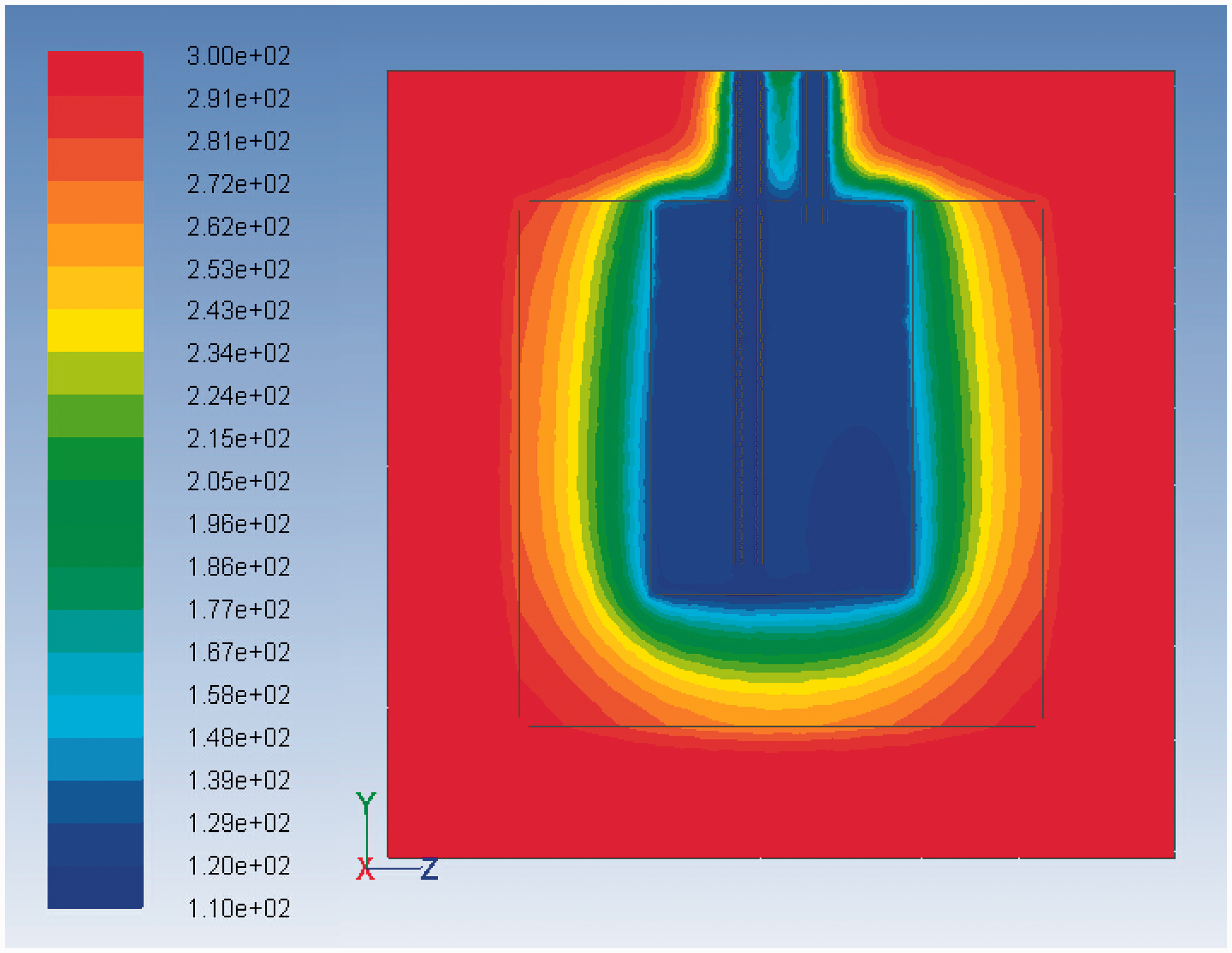
Temperature distributions of sample across a slice in the YZ plane at 850 s. Temperature field showed the region as mainly generated in the coal part (unit: K).
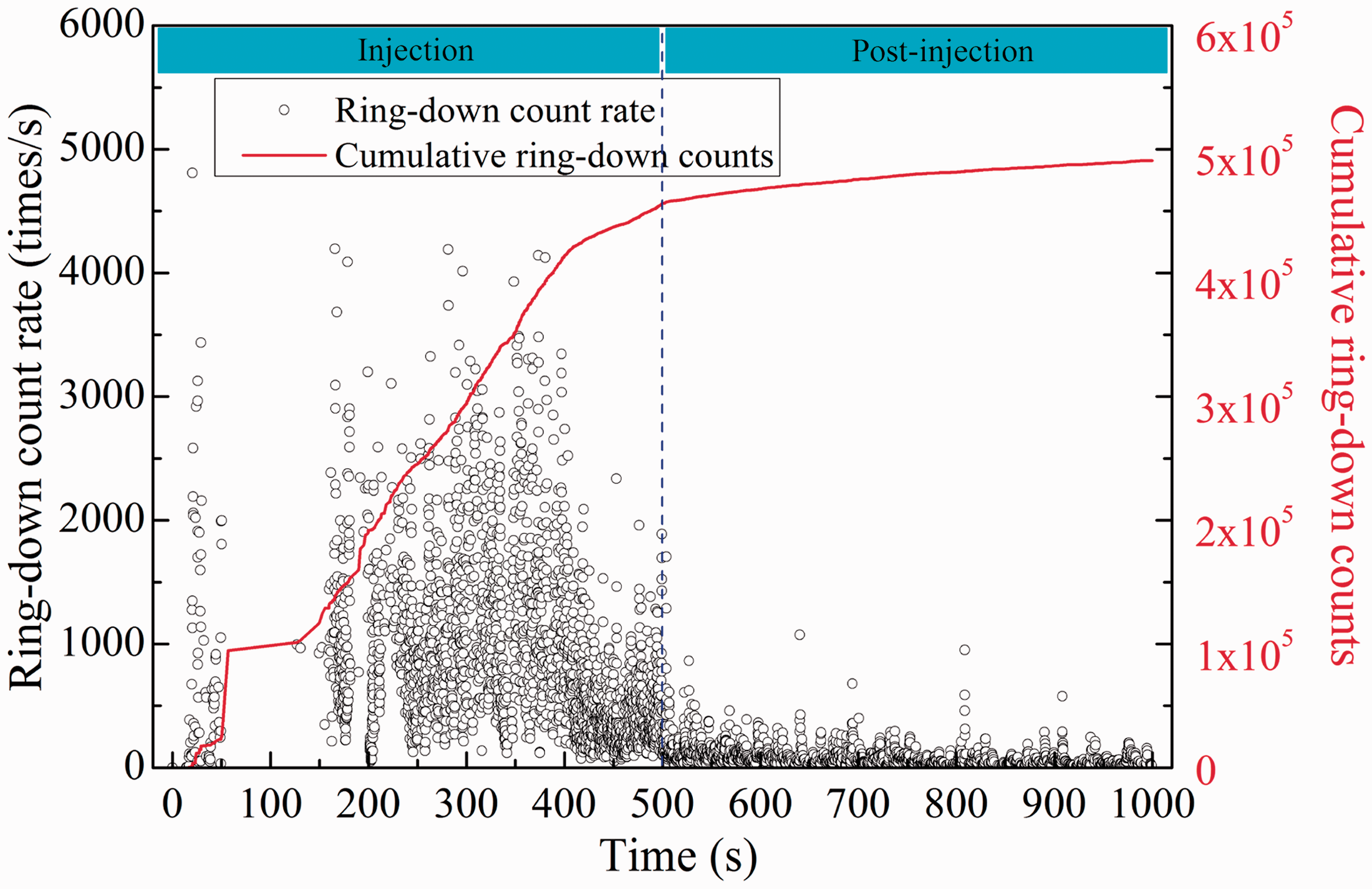
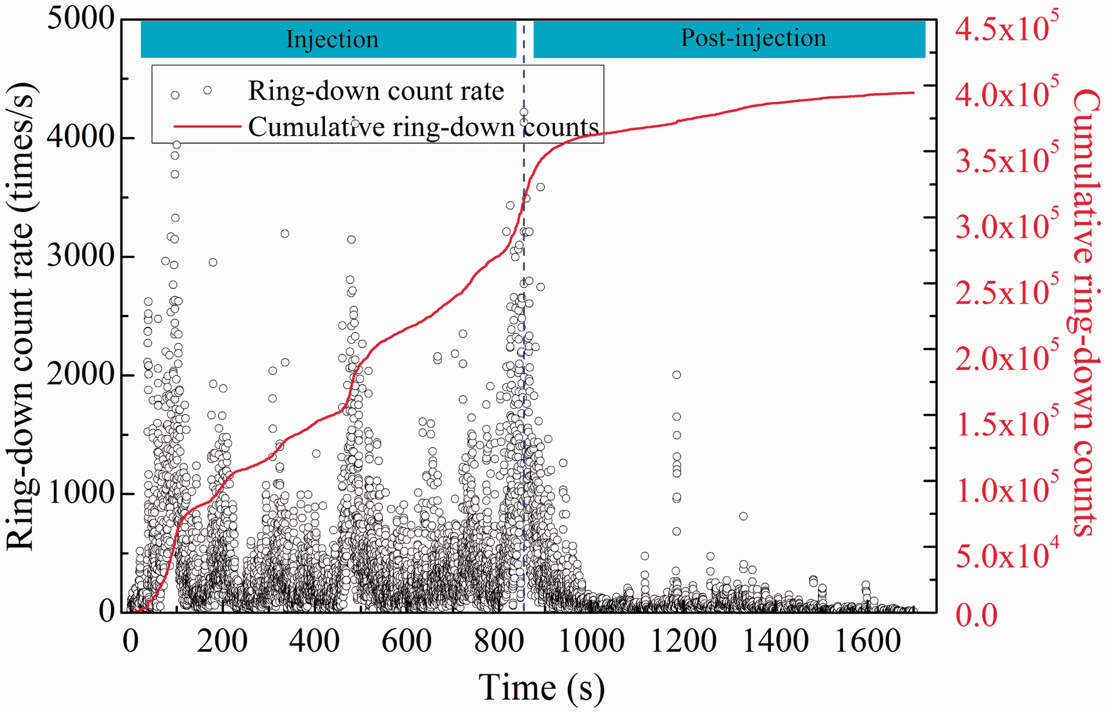
Figures 8 and 9 show the AE ring-down count rate, cumulative ring-down counts, and time curves of coal samples AE-1# and AE-2#. In Figure 8, the data for ring-down count around 100 s were missing. According to the experimental results and the ring-down data of sample AE-2#, the coal sample AE-1# should be also damaged during this period. It was probably because that the data acquisition software went wrong during this period. In this paper, we mainly researched the effect of liquid nitrogen injection on AE characteristics of coal samples. Thus, the cryogenic cracking effect of coal sample could be analysed based on the data during other periods. In addition, the whole curve shape of cumulative ring-down counts at injection and post-injection stages can also be used to evaluate the cracking features of coal due to liquid nitrogen cooling. As shown in Figures 8 and 9, the AE characteristics of the coal were affected by liquid nitrogen injection obviously. During the liquid nitrogen injection, or post-injection, period, the cumulative ring-down counts increased linearly with time; however, the increase rate of cumulative ring-down counts during liquid nitrogen injection was much greater than the post-injection period. The cumulative ring-down count is the sum of all ring-down counts within a certain time period, which represents the cumulative extent of any damage suffered by the material. As shown in Figures 8 and 9, the cumulative ring-down counts of coal increased quickly upon liquid nitrogen injection. For example, from 200 to 400 s, the cumulative ring-down counts of samples AE-1# and AE-2#, respectively, increased by 115.63 and 48.90%. Figures 10 and 11 show the temperature distributions across a slice in the YZ plane at 200 and 400 s: these figures indicated that as the duration of liquid nitrogen injection increased from 200 to 400 s, the cooling region in the coal sample grew significantly. It suggested that more micro-fissures would be generated inside the coal sample, thereby leading to a significant increase in cumulative ring-down counts. It was also proved that, with the continuous injection of liquid nitrogen, the damage and extent of cracking in the coal were improved.
AE ring-down count rate, cumulative ring-down counts, and time curves: rock sample AE-1#. AE characteristics presented great difference between injection and post-injection stages.
AE ring-down count rate, cumulative ring-down counts, and time curves: rock sample AE-2#.
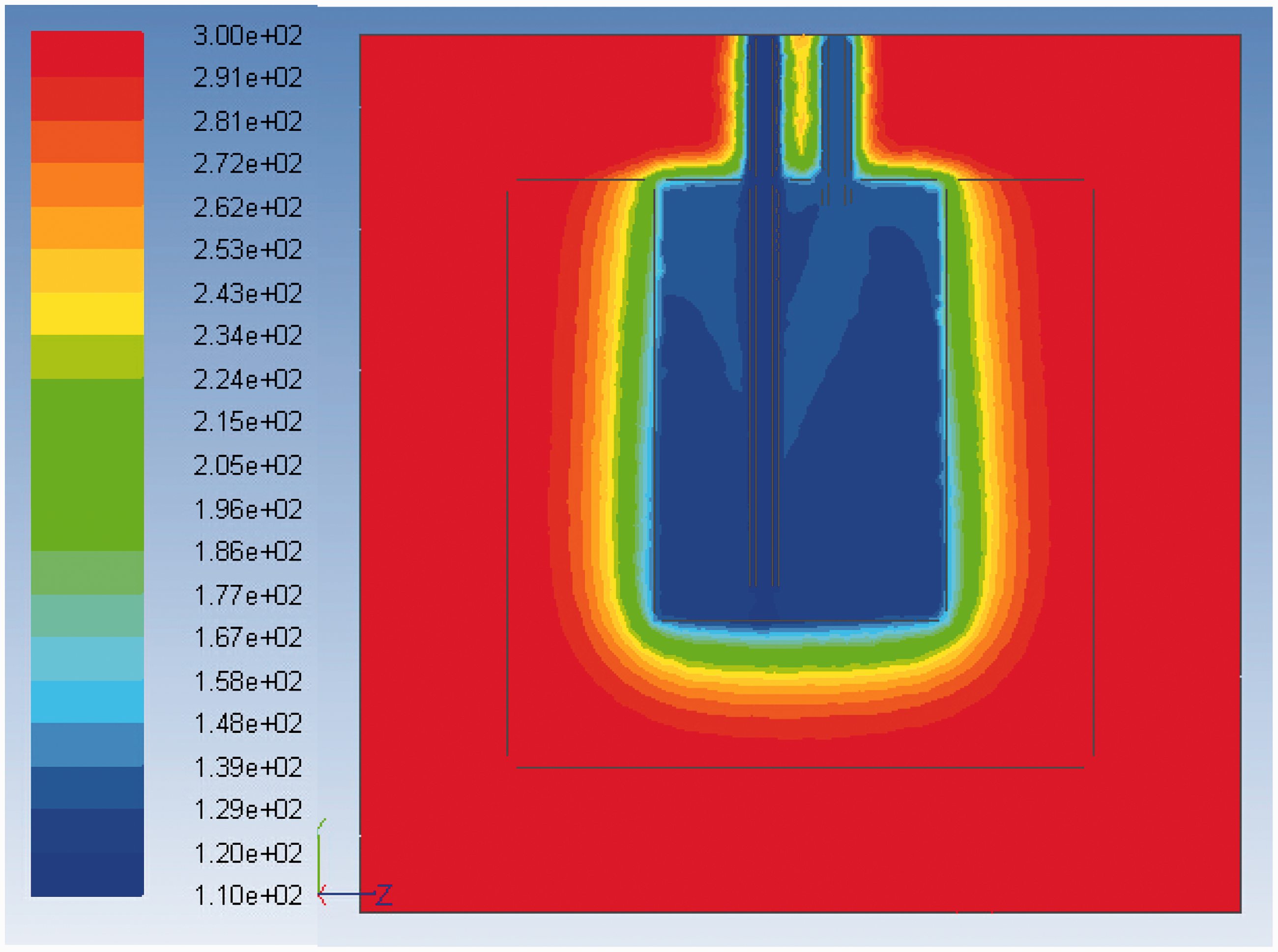
Temperature distribution across a slice in the YZ plane at 200 s. The coal part was not cooled efficiently (unit: K).
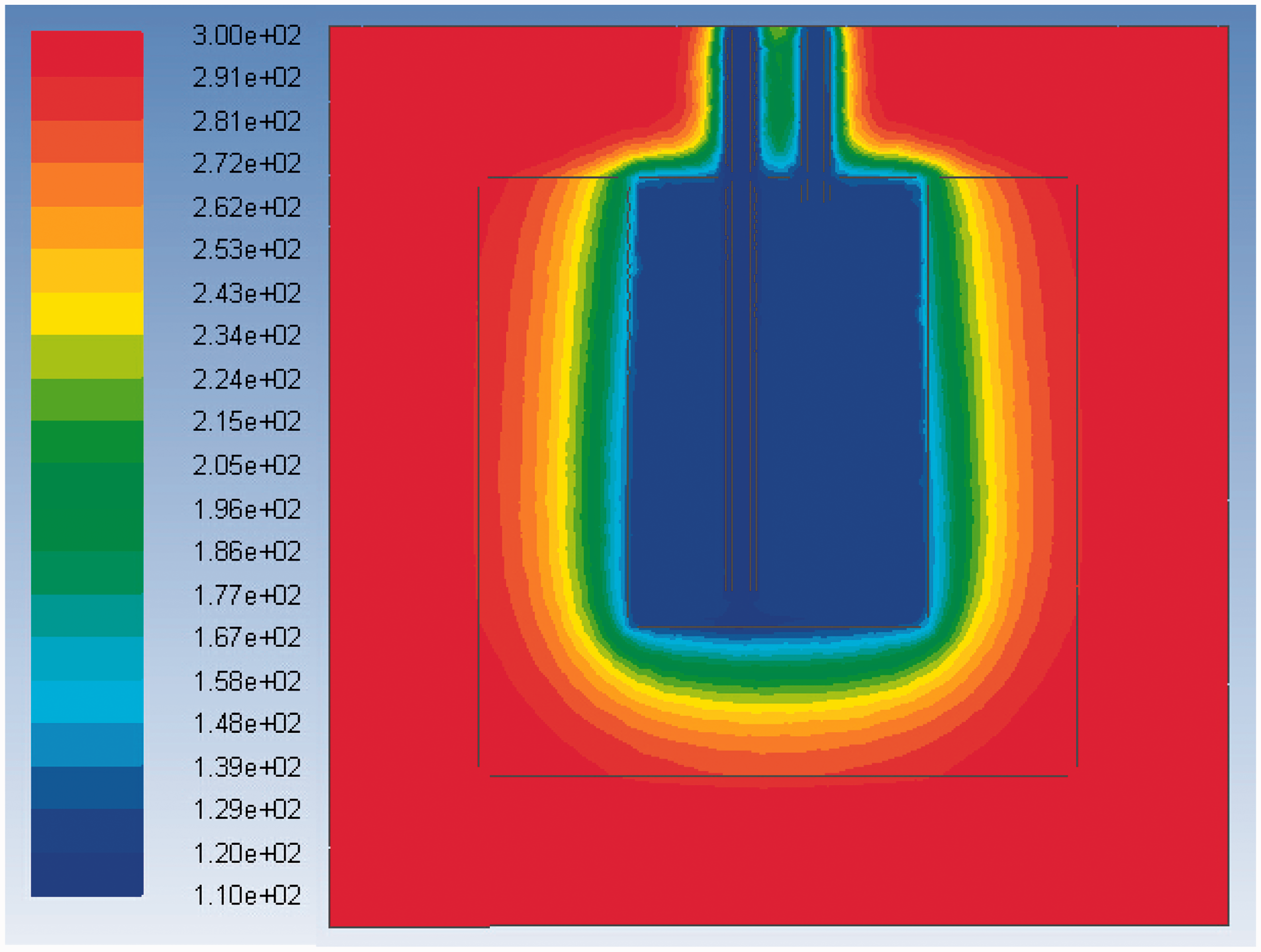
Temperature distribution across a slice in the YZ plane at 400 s. The cooling region inside the coal was further expanded (unit: K).
As the liquid nitrogen injection ceased, the cumulative ring-down counts increased slightly with time, which indicated that the damage inside the coal samples was minimal. In addition, during liquid nitrogen injection, the ring-down count rate of coal was greater than that in the post-injection period. For sample AE-1#, the average ring-down count rate during liquid nitrogen injection was about 1033.03 times/s (about 14.45 times greater than that in the post-injection period). For sample AE-2#, the average ring-down count rate during liquid nitrogen injection was 3.41 times greater than that in the post-injection period. Thus, coal could be cracked using the cryogenic temperature of liquid nitrogen to improve the extent of fracture formation in coal rock during fracturing.
The cumulative ring-down counts that corresponded to liquid nitrogen injection and post-injection periods were analysed statistically to investigate cracking effect of liquid nitrogen on coal samples. As shown in Figures 8 and 9, the cumulative ring-down counts during liquid nitrogen injection were much larger than those during the post-injection period. For sample AE-1#, the cumulative ring-down counts were 456,106 at the end of the liquid nitrogen injection stage, which was about 12.08 times greater than that in the post-injection stage. For sample AE-2#, the cumulative ring-down counts during liquid nitrogen injection were 307,832, which was 2.56 times greater than that in the post-injection stage. This was because that as the liquid nitrogen was injected into the sample, thermal shock was generated, resulting in cracking within the coal. In this condition, the initiation and propagation of micro-fissures were promoted; thereby abundant AE phenomena being generated. However, during the post-injection period, with the coal sample warming up, just a few micro-fissures could be created. Thus, the AE activity was very weak and the ring-down counts were deficient.
As described above, the AE characteristics presented different for samples AE-1# and AE-2#. AE activity is closely related to the damage status in materials and can be used to estimate the damage degree. If abundant AE ring-down counts were monitored inside the materials, it means that the materials are damaged seriously. As the mesoscopic aspect concerned, the damage can be characterized in the form of micro-fissures development. Thus, the increase in cumulative ring-down counts indicated that the micro-fissure inside the coal sample also expanded. Coal, as a porous medium, usually has large initial defects, such as cleats, micro-fissures. These defects will affect the coal mechanical properties significantly. Due to the external force (or temperature variation), the local stress will be generated near the tips of micro-fissures or cleats. As the local stress is greater than the frictional force between the crack surfaces, the new micro-fissures will be created. Hence, the coal samples with different cleat and micro-fissure distributions, the micro-fissures inside the coal will present different development characteristics. This was also the reason why the samples AE-1# and AE-2# had different AE characteristics during liquid nitrogen injection.
Fractal characteristics of the coal AE parameters
Fractal correlation dimension model of the AE parameters
As shown in Figures 8 and 9, the AE parameters of coal due to liquid nitrogen cooling presented significant randomness and discreteness. It was difficult to reveal the micro-cracking evolution of coal according only to the AE signals, let alone connect AE phenomena with damage and cracking processes. Fortunately, previous research indicated that the AE parameter time series data have fractal characteristics in time and space and its fractal characteristics can be described with a correlation dimension D (Zhu et al., 1991). Therefore, fractal analysis was undertaken to investigate the evolution of the damage to, and cracking of, coal during liquid nitrogen cooling. The Grassberger–Procaccia algorithm was used to expand the AE signal time series data to a higher-dimensional space (Grassberger and Procaccia, 2004). This algorithm regards the AE basic parameter time series data, such as ring-down counts, as a one-dimensional series X with n data points

Based on series X, a new m-dimensional space can be built as follows
First, the top m data points of series X are used to form the first vector of the new space

From the second data point of series X, the second vector including m data points is built

Finally, N (where N = n − m + 1) vectors are built. With these N vectors, a new m-dimensional space is constituted and its correlation function can be expressed as
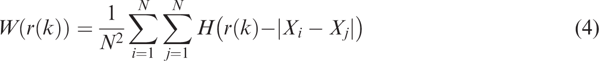
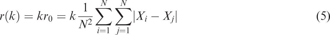
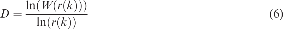
Given g scale coefficients, and g data points, (ln W(r(k)), ln r(k)) can be found in double logarithmic coordinates. If the curve fitting data points (ln W(r(k)), ln r(k)) are linear, the AE parameter series is proved to have fractal characteristics and the slope of the fitting curve is the correlation dimension D
Changes in AE correlation dimension
As Wu et al. (2012) pointed out that micro-crack evolution may also be evaluated efficiently according to the calculated correlation dimension D. From the fractal perspective, the failure of rock is a process of micro-crack distribution evolution from chaotic to ordered, which ends in a macro-rupture. Rock, as a porous material, has abundant randomly distributed micro-fissures. Under the action of liquid nitrogen cooling, these micro-fissures expanded and propagated due to the thermal stress. The AE correlation dimension, as the measurement of the randomness, represents the statistical evolution of the micro-fissures. Thus, as an overall trend, the correlation dimension D increased with the injection of liquid nitrogen (Figures 12 and 13). This phenomenon also suggested the growth of micro-fissures due to liquid nitrogen cooling. Upon cessation of liquid nitrogen injection, the correlation dimension D immediately decreased, which indicated that the micro-failure was weakened during the post-injection period.
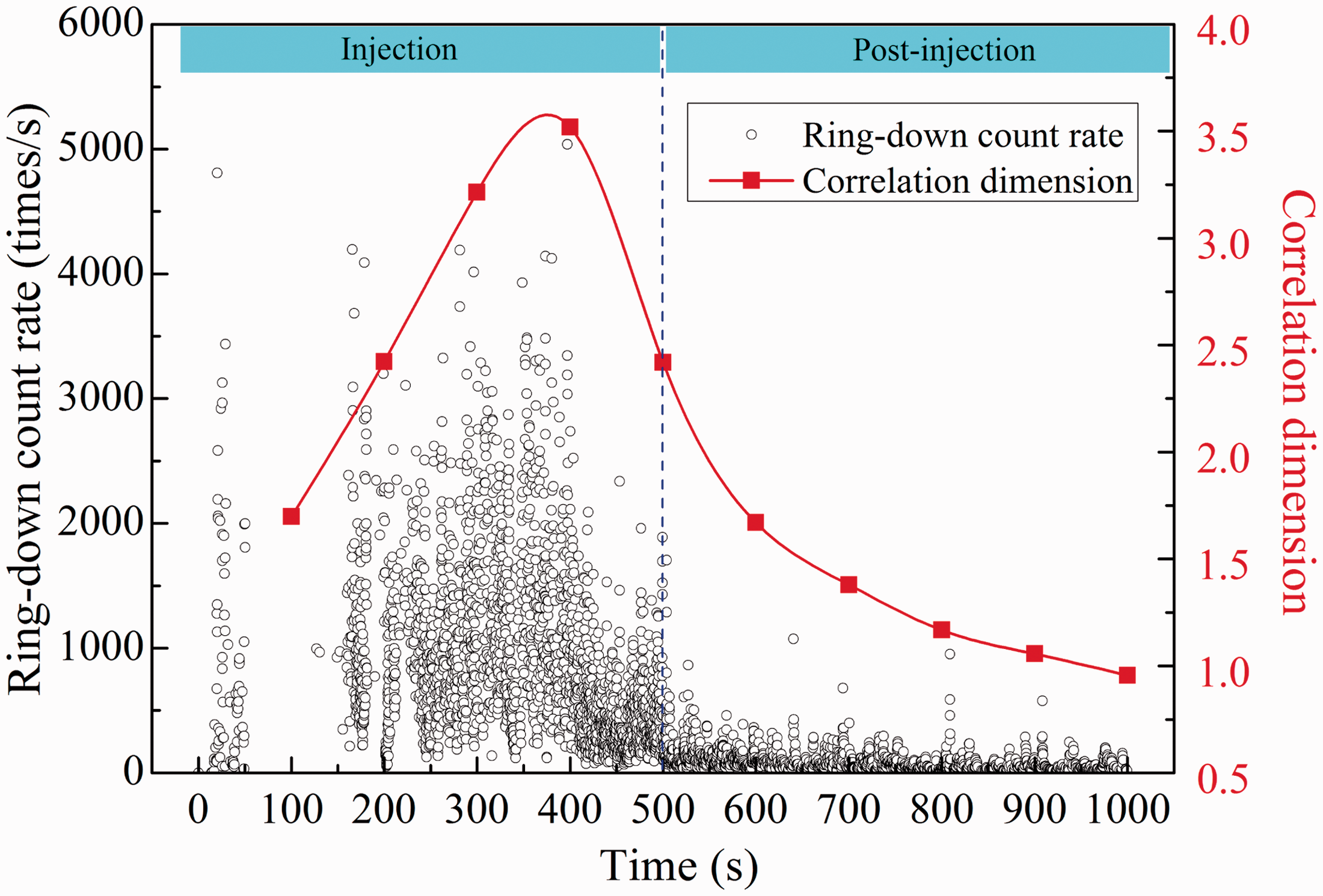
AE ring-down count rate and its correlation dimension D-time curves: sample AE-1#. The correlation dimension curve was closely related to the damage status of rock sample.
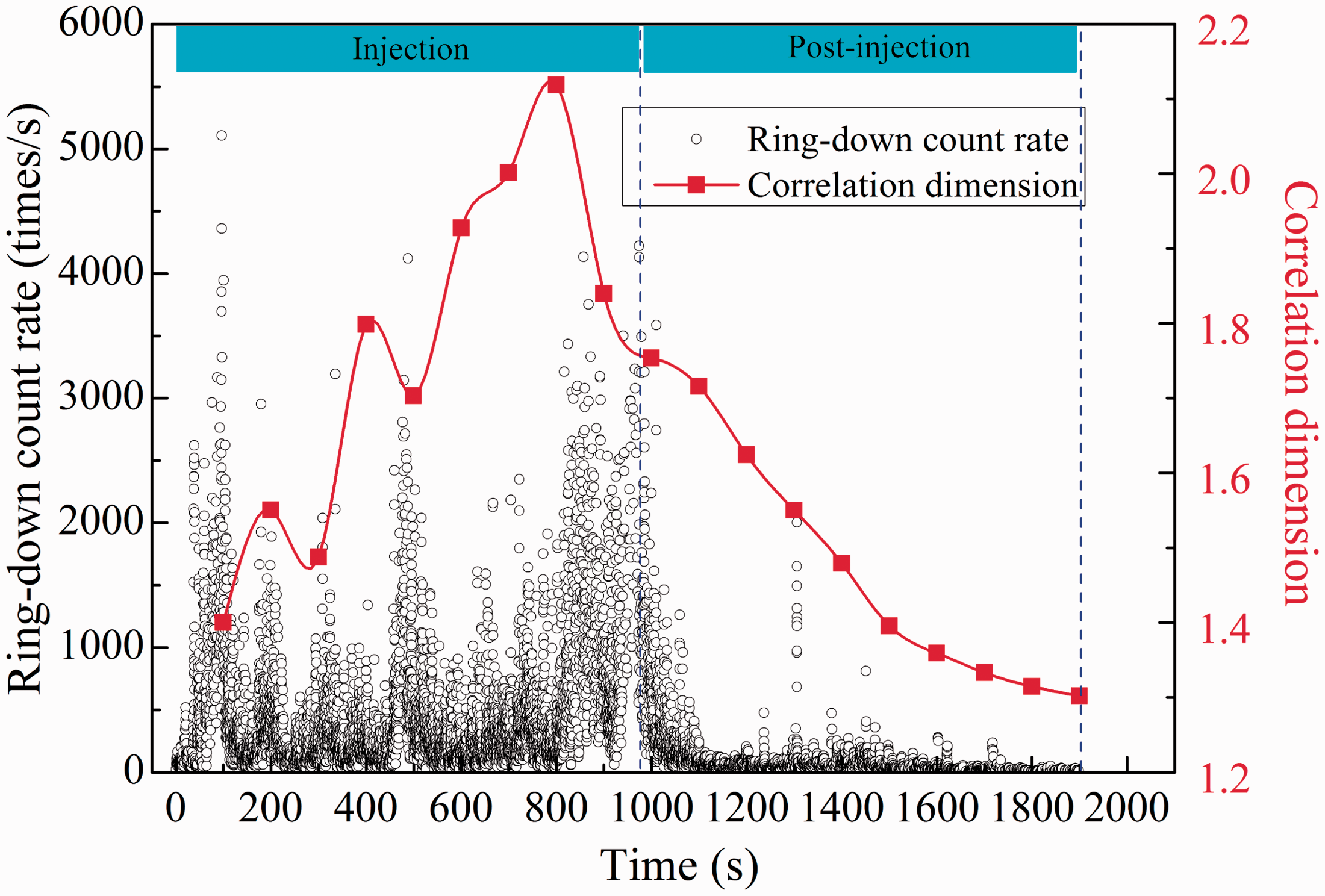
AE ring-down count rate and its correlation dimension D-time curves: sample AE-2#.
In addition, as shown in Figure 13, at certain times (e.g. 300 or 500 s), the correlation dimension D would decrease, and then continue to increase with the injection of liquid nitrogen and the associated cooling. The decrease in the correlation dimension D cannot be attributed to the reduction in micro-cracking. On the contrary, as the local micro-fissures expanded, partial random micro-fissures began to interpenetrate and thereby developed into the local failure region. Consequently, the damage to, and cracking of, these coal samples showed characteristics of orderliness and localization, which led to the correlation dimension tending to decrease temporarily.
The AE activity of rock is a type of statistical rule, which is closely related to the damage evolution of rock. In rock damage research, AE signal characteristic parameters (ring-down counts, energy counts, etc.) are usually used to evaluate the cracking characteristics; however, they have some difficulties in quantitatively describing the process of micro-cracks evolution, especially from the chaotic status to the ordered status. Thus, in order to explain the damage and failure process of rock, the one-dimensional AE signal parameters should be transformed into the statistical data by the mathematical method. The previous researches indicated that the AE parameter series have fractal characteristics in time and space and its fractal characteristics can be described with correlation dimension D. From the fractal view point, the failure of rock is the process of the micro-fissures distributions evolving from chaotic to ordered. The correlation dimension D was closely related to the evolution characteristics of micro-fissures. If the coal samples had different micro-fissures distributions, the evolution characteristics of micro-fissures will differ from each other correspondingly during liquid nitrogen injection. It was also the reason why the correlation dimension D was different for samples AE-1# and AE-2#.
Change in wave velocity
Generally, the damage and cracking inside the rock present in the form of micro-fissures, but they cannot be measured directly in the laboratory. In this case, other physical or mechanical parameters are usually employed to evaluate the extent of damage and cracking in a material. In rock mechanics, ultrasonic wave technology is an important method used to detect the extent of damage suffered by a rock sample. For the same type rock, the wave velocity of rock is controlled by the volume of micro-fissures. The more micro-fissures are present in the rock, the smaller the wave velocity therein. Here, the P-wave velocity was selected to investigate the damage and cracking effects caused by liquid nitrogen cooling. The relationship between the amount, and extent, of damage and wave velocity can be expressed as follows (He, 2016; Lin and Chen, 2005)
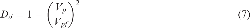
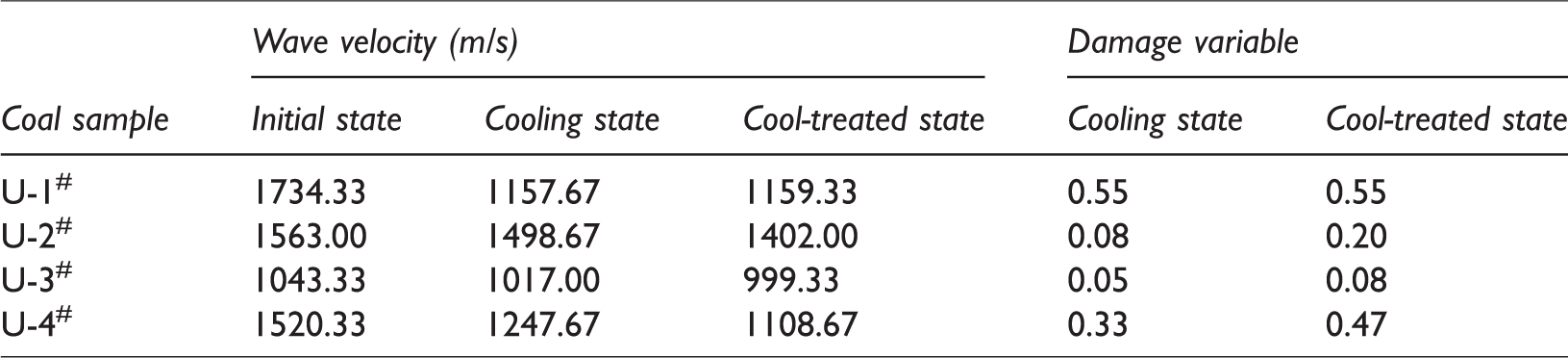
Here, the value of Vpf was set to the wave velocity in the coal sample in its initial state. The damage suffered in cooling and cool-treated states is as shown in Table 3. The wave velocities of coal samples decreased due to liquid nitrogen cooling. In the cooling state, the wave velocity decreased (on average) by 14.46%. Sample U-1# showed the largest decrease and sample U-3# showed the smallest decrease. As the cryogenic samples recovered to laboratory ambient temperature (about 25.0°C), the wave velocity further decreased. As shown in Table 3, the wave velocities of coal samples decreased by 18.68% (on average) in the cool-treated state. Thus, it was further proved that, as the coal samples were allowed to warm, further damage was generated, which could enhance the extent of damage to, and cracking of, the coal. According to equation (7), the damage variables in cooling state were 0.050–0.55, and they increased (on average) by 62.80% as the samples were allowed to warm to room temperature.
Wave velocities and damage variables of coal samples in different states.
Change in tensile strength
Rock, as a porous medium, usually contains many natural micro-fissures, which have a significant effect on its mechanical properties. In general, the amount of damage in the material is positively related to the proportion of micro-fissures. For the same type of rock, a sample containing more micro-fissures usually has a lower mechanical strength. As described above, the wave velocity of coal decreased due to liquid nitrogen cooling, which indicated the growth of the micro-fissures therein. As shown in Table 4, because of being cooled in liquid nitrogen, the tensile strength of coal decreased. For samples in the cooling state, the tensile strength decreased (on average) by 17.39%. According to the previous research, under cryogenic conditions, two major changes will be produced in the pore structure of rock (Xu et al., 2013): (i) the mineral grains of the rock undergo shrinkage deformation due to the temperature decrease, and (ii) micro-fissures expand as result of thermal stress. The former change will make the pore structure more compact; however, the latter change will improve the volume and density of micro-fissures (i.e. cracking occurs within the rock). If the influence of compaction on rock is stronger than the cracking effect, the mechanical properties will, on the whole, be improved and vice versa. In these experiments, the tensile strengths of coal samples in the cooling state were smaller than those in the initial state. This indicated that, during liquid nitrogen cooling, the cracking effect inside the coal was much stronger than the compaction effect which was mainly because the strength of the mineral grains and the inter-grain cement were so low that micro-fissures were easily generated by the liquid nitrogen cooling. Even though the compaction effect of the pore structure may occur inside the coal, it played a limited role in balancing the expansion of the micro-fissures. Thus, the coal samples in their cooling state presented a smaller tensile strength than in their initial state.
The effect of liquid nitrogen cooling on coal tensile strength.
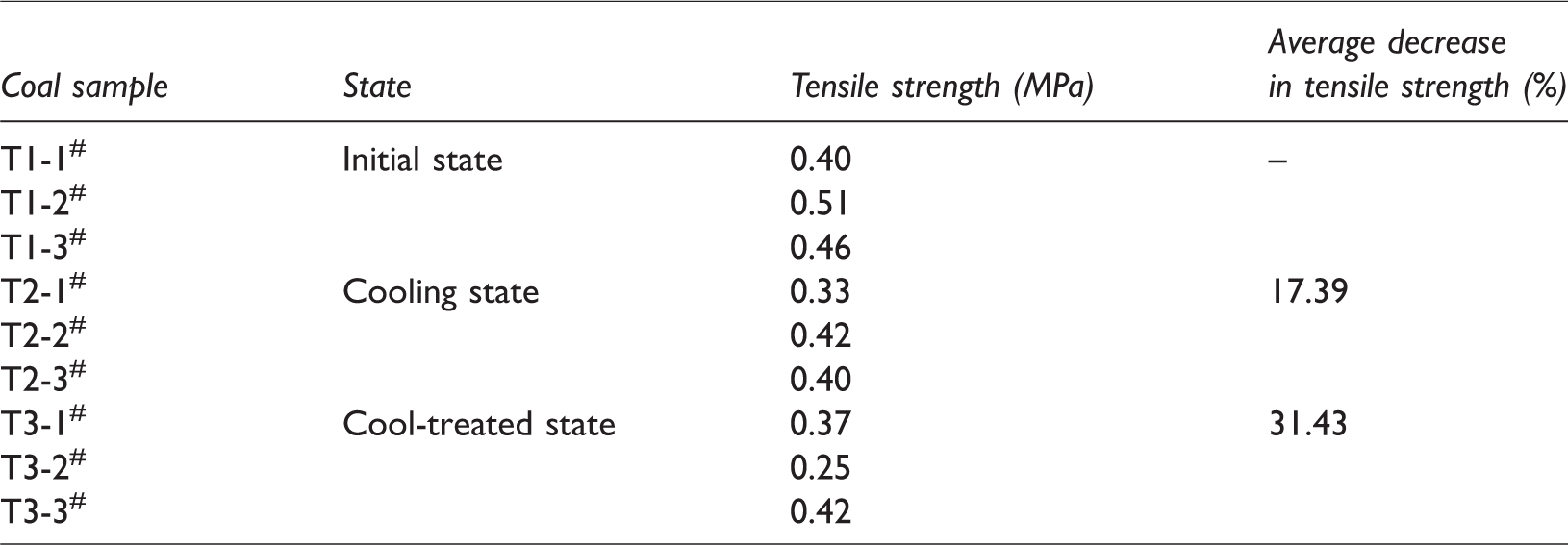
For samples in Group T3, which were subjected to tensile testing after recovery to room temperature (about 25.0°C), their average tensile strength presented a larger decrease. As shown in Table 4, the average tensile strengths of these samples decreased by 31.43%. This result further proved that during the cryogenic processing of these coal samples and their subsequent warming, the micro-fissures would expand due to the increase in temperature.
Conclusions
In this paper, the effect of liquid nitrogen cooling on coal cracking and mechanical properties was researched by the experimental methods, including AE tests, ultrasonic tests, and tensile strength tests. The AE experimental results showed that as the coal came into contact with liquid nitrogen, continuous damage and cracking were generated. At the same time, the average AE ring-down count rate and cumulative ring-down counts during liquid nitrogen injection were, respectively, at most, 14.45 and 12.08 times greater than that during the post-injection period. The ultrasonic experimental results indicated that liquid nitrogen can promote the expansion of micro-fissures inside the coal samples, which can be presented by the decrease in the wave velocity. In the cooling state, the wave velocity decreased (on average) by 14.46%, and in the cool-treated state, this value increased to 18.68%. The coal samples, in their cooling and cool-treated states, had lower tensile strengths than the samples in the initial state. For samples in the cooling state, the tensile strength decreased (on average) by 17.39%. For the samples in a cool-treated state, this value further increased to 31.43%. In sum, liquid nitrogen cooling could crack the coal, which caused the expansion of micro-fissures, the decrease in wave velocity, and the reduction in mechanical strength. This was great beneficial to the enhancement of near wellbore permeability and the improvement of fracture degree in a coal during CBM development and fracturing.
Footnotes
Acknowledgements
We would like to acknowledge Mr Xiaoguang Wu and Xiao Deng from China University of petroleum, for their critical assistance in the work, which significantly improved the quality of the manuscript.
Declaration of conflicting interests
The author(s) declared no potential conflicts of interest with respect to the research, authorship, and/or publication of this article.
Funding
The author(s) disclosed receipt of the following financial support for the research, authorship, and/or publication of this article: The authors would like to thank the financial support from National Natural Science Foundation of China (No. 51604263), the Natural Science Foundation of Jiangsu Province (No. BK20160252), the National Natural Science Foundation of China (No. 51574219), the State Key Research Development Program of China (No. 2016YFC0600705), and the Priority Academic Program Development of Jiangsu Higher Education Institutions (PAPD2014).