
Abstract
Recovering waste heat from urban infrastructures is becoming increasingly important as the UK strives to decarbonise heat, which remains one of the main challenges in the transition towards net zero. The Bunhill Waste Heat Recovery (WHR) System represents a first of its kind scheme that will recover waste energy from a ventilation shaft of the London Underground (LU) transport network. The system is based upon the installation of a heat recovery heat exchanger that consists of cooling coils and a reversible fan. The coils are connected to a heat pump that supplies low-carbon thermal energy to the Bunhill Heat Network in Central London. One particularly important aspect of the Bunhill WHR system is its ability to operate in a way that not only provides heating to the local heat network, but can also simultaneously supply cooled air to the LU tunnels depending on the operation of the reversible fan. The current paper estimates the potential cooling benefit that could be achieved with the WHR system based upon the development of a mathematical model. The model is able to predict the condition of the coil surface according to air inlet parameters, and this is used to calculate the latent and sensible cooling loads, which are applied to simulate how the system affects the local tunnel environment, with peak temperature reductions of up to 7.2 K being estimated for adjacent stations in 2030. The results from the investigation are presented together with recommendations for further development and future deployment of heat recovery from metro systems, as this technology could be applied across London and elsewhere to deliver significant carbon and cost savings while improving the thermal environment of railway tunnels.
Practical Application
This work investigates the cooling potential behind a practical project that involves recovering waste heat from the LU network. As electrification leads to an increased deployment of heat pump and district heating systems, waste heat could become a valuable resource for maximising energy efficiency, even more so when additional cooling benefits can be achieved. This paper aims to explore the impacts of cooling on railway tunnels, emphasising how secondary benefits, which are many times overlooked, could be critical to making waste heat recovery economically feasible, maximising its potential as a key technology for decarbonising heat.
Keywords
Introduction
Background
In 2019, the United Kingdom became the first major economy to commit to a legally binding target of cutting greenhouse gas emissions (GHG) to net zero by 2050. This target was motivated by the increasing uptake of renewable energy sources for electricity production in the UK, with renewables reaching an all-time record of 37% of the power generated in 2019 1 ; a number expected to grow continuously in the coming years. As the UK aims to further reduce its contribution to climate change and deliver net zero, decarbonising heat becomes one of its main challenges, as the sector is responsible for nearly half the energy consumption and a third of carbon emissions in the country. 2 This is associated with the dominance of fossil fuels in the UK’s heating sector, with 85% of British households being heated by natural gas, and only 5% having low-carbon heating technologies. 3 The ongoing decarbonisation of the electricity grid, together with the current dependence of the heating industry on natural gas, makes the electrification of heat, for example, through the use of heat pumps, a great opportunity to help reducing the carbon footprint of UK buildings, as recognised by the UK Government’s Heat and Buildings Strategy. 4
Within that context, heat networks represent a key technology, particularly in densely populated urban areas, as they enable the coupling between heating and other energy vectors and can benefit from economies of scale. As part of its net zero Strategy, the UK Government expects the annual energy supply from heat networks to grow from 14 TWh in 2019 to 70 TWh in 2050, which would represent around 20% of the UK’s domestic heating demand in that year. 5 Another advantage of district heating is its ability to make use of waste heat from a variety of urban infrastructures, which could be widely exploited in London and other cities across the UK and globally. The Heat and Buildings Strategy has acknowledged waste heat as low-carbon energy that should be utilised by heat networks, with underground railways being highlighted amongst potential sources. 4 This emphasises the important role that waste heat is expected to play in the energy transition, which could be even greater if secondary benefits such as cooling are explored.
Waste heat from the London underground
There are many sites in urban settings from which it is possible to capture waste heat, such as industrial plants, data centres, electricity distribution systems, sewers and supermarkets. One source of particular interest in the UK is the London Underground, which has a total network length of 402 km (45% in tunnels) and carries around 1.35 billion passengers per year. 6 The energy inputs required to provide this level of service lead to significant amounts of thermal energy being released from the sheer operation of the trains. In 2016/2017, the Underground consumed over 1700 GWh of electricity, with around 500 GWh of energy ending up degraded and released as waste heat. 7 The current thermal environment of the LU means that there is significant potential for recovering waste heat from tunnels, while cooling solutions are expected to gain importance as air temperatures rise in the future due to climate change, which is likely to increase train service delays. 8 This opportunity led to the development of the Bunhill WHR System, a first of its kind scheme that will recover waste energy from a ventilation shaft of the LU network, whilst also being able to supply cooling to the tunnels, as introduced in Ref. 9. This paper builds upon an analysis of the cost and carbon benefits of the WHR system, 10 and aims to estimate how the cooling effect provided by the heat recovery coils (HRC) may impact the LU environment in the future.
The Bunhill waste heat recovery system
The London Underground WHR system was introduced into the Bunhill Heat Network as part of an extension project known as Bunhill 2. The system recovers waste heat from the City Road ventilation shaft, located on the Northern Line between Angel and Old Street stations, in Central London. The main components of the WHR system are a reversible fan, HRC with a nominal capacity of 780 kW, a 1 MW two-stage ammonia heat pump, and a coolant loop that connects the coils to the heat pump. The WHR system was constructed within a new energy centre, which also houses a 50 m3 thermal store and two 237kWe/372kWth combined heat and power (CHP) units. These additional heat sources, together with the energy centre from the initial network, enable the system to operate flexibly while meeting a heat demand associated with 1350 dwellings, two leisure centres and a local primary school. As the main novelty of Bunhill 2 is associated with heat recovery from the Underground, the modelling work focuses on the WHR scheme. More information on system design can be found in Ref. 9.
An essential feature of the Bunhill WHR system is its ability to supply cooled air to the LU tunnels whilst simultaneously delivering heat to the local district heating network. This depends on the direction in which the reversible fan operates. If operating in extract mode, the system utilises tunnel air as the heat source and no cooling is provided to the network. However, when operating in supply mode, the system recovers heat from ambient air, which is cooled down in the process, before being supplied to the tunnels. Both extract and supply modes are illustrated in Figure 1. Conceptual schematics of the WHR system operating in extract and supply modes.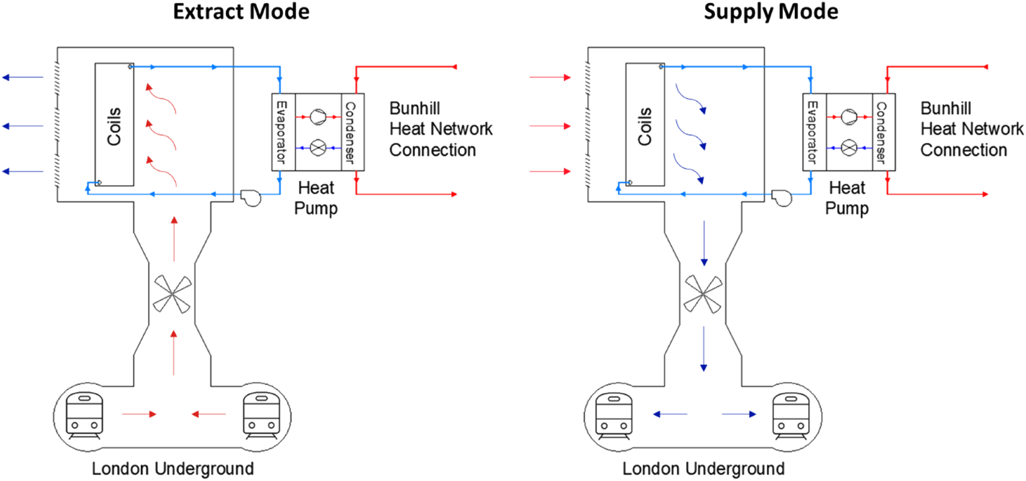
Modelling of the WHR system
In order to investigate the performance of the WHR system and its associated cooling benefit, a mathematical model was developed using the commercial software tool Engineering Equation Solver (EES).
11
The WHR model is able to iteratively solve thermodynamic balance equations across the system, being used to determine its energy consumption, as well as heating and cooling outputs. The energy consumption calculations are associated with the electricity used to run the reversible fan ( Schematic highlighting energy inputs and outputs associated with the WHR model.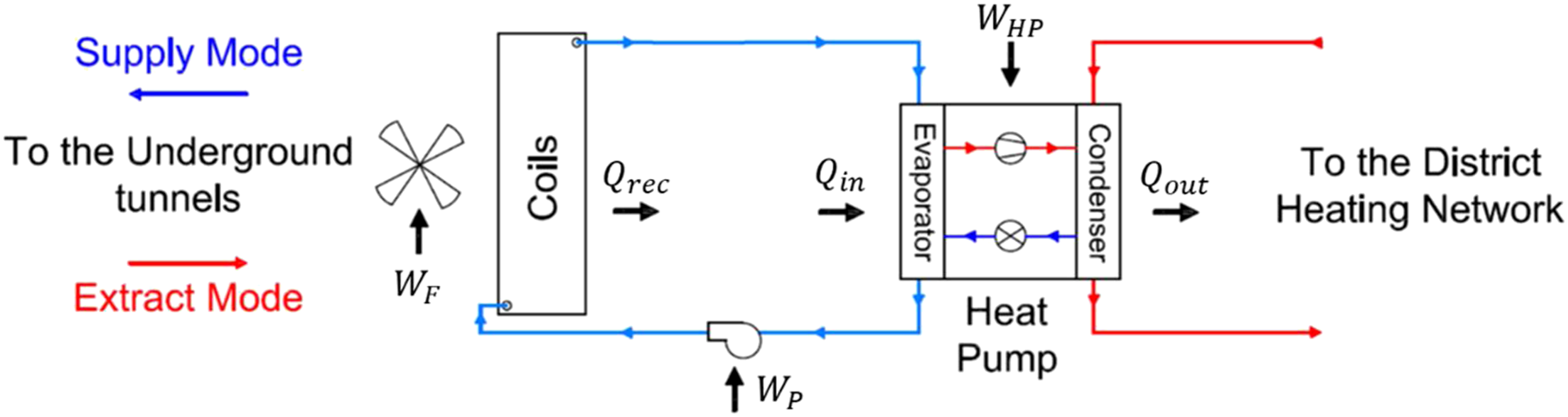
The WHR model simulates each of the components illustrated in Figure 2 and its outputs are calculated by solving the mass and energy balance between the coils and the heat pump. These outputs are illustrated in Figure 3, together with the main inputs and connections between the different components of the model. The model was validated against manufacturer’s data. The calculations are done in hourly time steps, based on temperature and relative humidity recordings from the ventilation shaft and the nearest available weather station, which were provided by Transport for London (TfL) and the Meteorological Office, respectively, for the period from January 2013 to January 2014. A brief description of each modelled component is provided in the following subsections, with emphasis on the HRC model, which is used to predict the air outlet conditions and the associated cooling effect produced by the WHR system. Framework for the WHR model, highlighting components, inputs and outputs.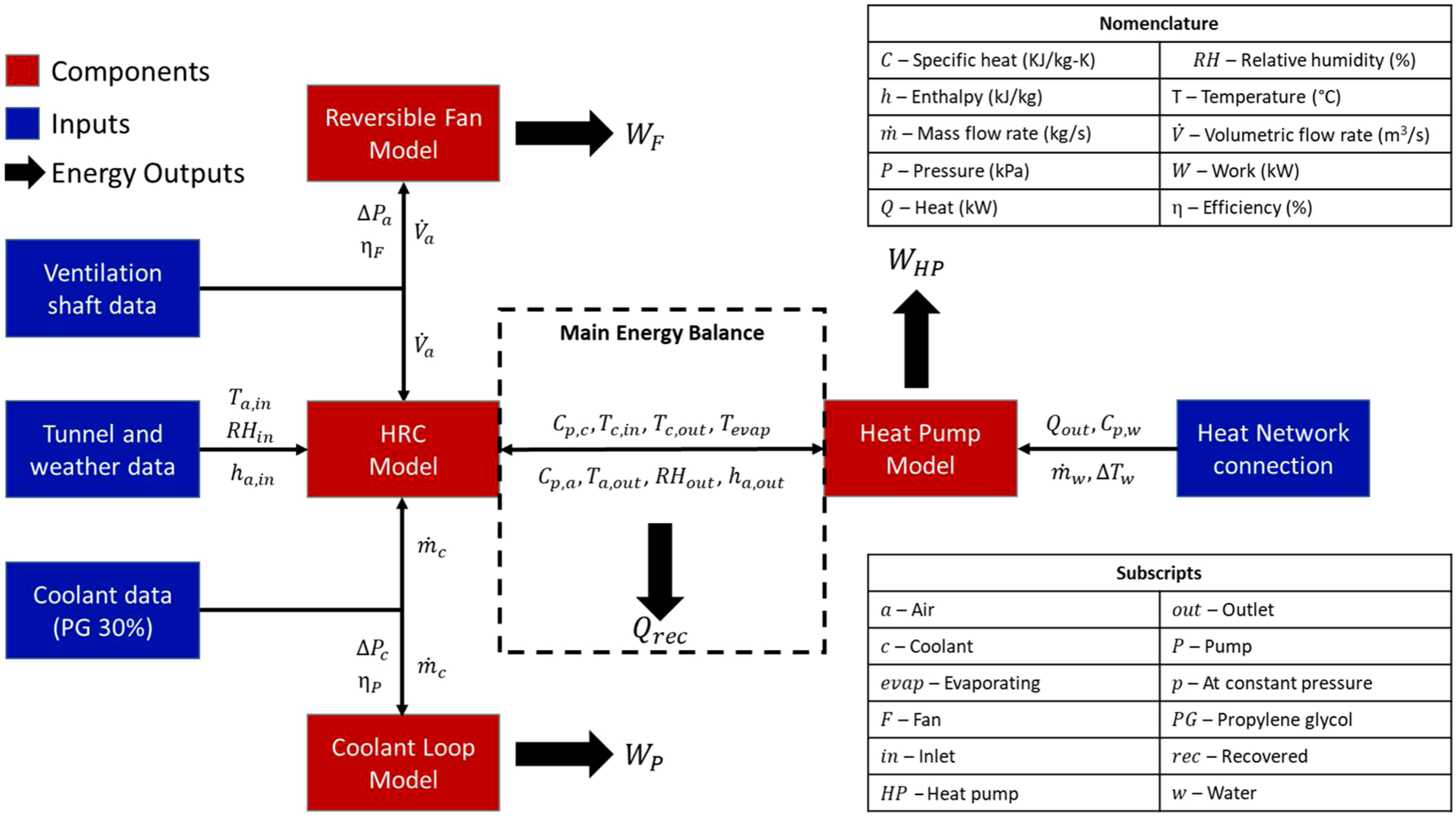
Two-stage heat pump
The two-stage heat pump was designed to operate with heat network flow and return temperatures of, respectively, 75°C and 55°C. The main components of the low stage are two plate-and-shell heat exchangers (PSHEs), namely, a desuperheater and a flooded evaporator that is connected to a small separator vessel, as well as a 6-cylinder reciprocating compressor with a nominal motor power of 280 kW. As for the high stage, its main components include two parallel reciprocating compressors with 4 cylinders and a nominal motor power of 90 kW each, as well as three PSHEs that act as a desuperheater, a condenser and a subcooler. The two cycles are connected by a separator tank, where saturated ammonia is kept at constant pressure. The model determines the coefficient of performance (COP) of the heat pump by calculating different evaporating temperatures associated with the energy balance illustrated in Figure 3. The heat transfer at the evaporator is calculated using correlations developed by Thonon 12 and Ayub 13 for single and two-phase flows, respectively. Based upon the design data shown in Ref. 9, a correlation between isentropic efficiency and low-stage pressure ratio can be derived. The high stage is modelled as a single heat exchanger with a fixed UA value, as the heat output and network temperatures are assumed constant. The pressure drops associated with components, as well as the suction and discharge lines for both stages, are also considered.
Reversible fan and coolant pump
The reversible fan and the coolant pump were modelled in order to estimate their energy consumption. The reversible fan model is based upon the additional pressure drop associated with the WHR system that needs to be overcome by the fan, as described in Ref. 9. The calculations considered a fan efficiency of 59.5% and pressure drops of 105.9 and 106.2 Pa associated with extract and supply modes, respectively. The pumping power is modelled as reported in Ref. 14, considering the coolant mass flow rate, an assumed pump efficiency of 50% and the pressure drops associated with the pipework, the evaporator and the HRC. The pipework was assumed as a 20-m loop consisting of DN150 stainless steel pipes and a minimum number of fittings.
Heat recovery coils
The HRC represent the location within the system where heat is recovered from either tunnel air or ambient air and cooling is delivered depending on the operation of the reversible fan. The coils consist of two banks, each with three 6-row deep modules of copper tubes with 4 fins per inch. The HRC are modelled as a single 12-row bank with 158 tubes each for reducing computational effort. The heat exchanger dimensions are 4.75 × 6.04 × 0.29 m, yielding a face area of 28.69 m2 and a surface area (


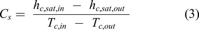
The thermodynamic phenomena associated with HRC requires complex modelling as it involves both heat and mass transfers from the air stream due to condensation. Mitchell and Braun
19
proposed a methodology for modelling humid air cooling coils that relies on an analogy of sensible heat transfer that simplifies calculations whilst estimating coil performance accurately. The methodology is based upon different heat transfer coefficient calculations for both fully dry and fully wet conditions, whilst a partial configuration can be represented by a combination of both dry and wet models, whereby the coil is divided into ‘dry’ and ‘wet’ sections, as shown in Figure 4. A schematic illustrating a counter-flow heat recovery coil with a partially wet surface.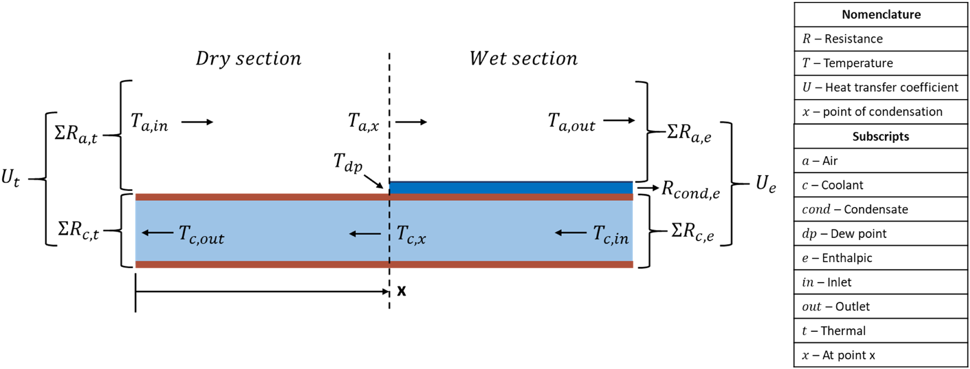
The dry section corresponds to the initial fraction of the heat exchanger (up to point


The energy and mass balances calculated by the WHR model also include the change in the moisture content of air, which is critical when estimating the amounts of latent and sensible cooling associated with the heat recovery process, and can be calculated based upon the enthalpy-effectiveness method. 20 The modelling approach described herein allows the coil surface and air outlet conditions to be determined, providing better understanding of the cooling produced by the WHR system and its impacts on the London Underground environment.
Estimating the performance of the WHR system
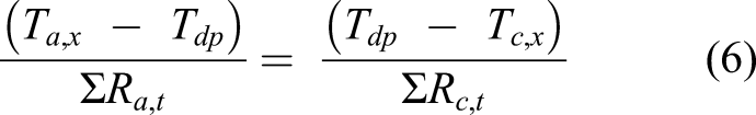
Different modelling scenarios for the WHR model, based upon fan operation mode.
The WHR model has been utilised to investigate the benefits of recovering waste heat from the LU against conventional technologies used for both heating and cooling, as reported in Ref. 10. This involved comparing the annual costs and carbon savings for each WHR scenario in Table 1, assuming a continuous operation with a 5% downtime, against a reference case of communal gas boilers and a ventilation shaft chiller system. The analysis showed how the WHR system could lead to significant annual carbon savings, which varied from 68% for scenario 1, when no cooling is provided, to 78% for scenario 5, when cooling is provided throughout the year. This means that the energy savings associated with cooling are able to compensate for the lower energy efficiency experienced by the heat pump when it operates for longer periods in supply mode. Furthermore, the cost analysis highlighted the importance of cooling in terms of increasing the economic performance of the WHR system, as savings of up to 30% against the reference case were estimated for a year-round operation in supply mode (scenario 5). This is particularly important as the WHR system would increase heating costs for all scenarios, with high electricity prices leading to negative heating cash flows against the reference case. However, it must be noted that elements such as flexibility and integration with other energy vectors in low-temperature networks were not considered in this analysis, and these are likely to reduce costs associated with WHR systems, as reported in Ref. 21.
One potential issue is that the recipient of the cooling benefit is the railway operator, whilst the heat network operator is the stakeholder having to bear the higher costs of producing low-carbon heat using electricity as fuel. This indicates the need for strong policy as enablers for WHR schemes, as the price disparity between gas and electricity and the higher levies applied to the latter represent a risk for the electrification of heat supply and the exploitation of low-grade waste heat sources in the UK. The Heat and Buildings Strategy has acknowledged this challenge and committed to announce plans to rebalance energy prices in 2022. Furthermore, the strategy has also highlighted district heating as a technology of great potential in densely occupied areas, with plans to develop heat network zones in locations where they represent the lowest cost and carbon solution. The Government also plans to invest £338 million until 2025 into a broader Heat Network Transformation Programme, which aims to incentivise the decarbonisation of existing heat networks and the construction of new low-carbon networks through the Green Heat Network Fund. 22 It is expected that these actions can fill the policy gap for heat decarbonisation, allowing urban waste heat recovery to flourish as the UK moves towards net zero.
Cooling the London underground
The analysis reported in Ref. 10 demonstrated how the cooling delivered by the WHR system could lead to significant benefits associated with carbon emission reductions and energy cost savings. Additionally, the cooling benefit can be expressed in terms of the potential reductions in platform temperatures that the WHR system would cause at the nearest stations to the ventilation shaft. Therefore, an investigation was carried out in collaboration with the engineering team at TfL to simulate how future network temperatures would be affected by the WHR system, utilising a bespoke modelling tool based upon the Subway Environment Simulation (SES) platform. SES is able to perform 1D simulations of the operation of trains in tunnels, being suited to model many different aspects of a subway environment, such as airflows, temperatures and humidity throughout stations, tunnels and ventilation shafts.
23
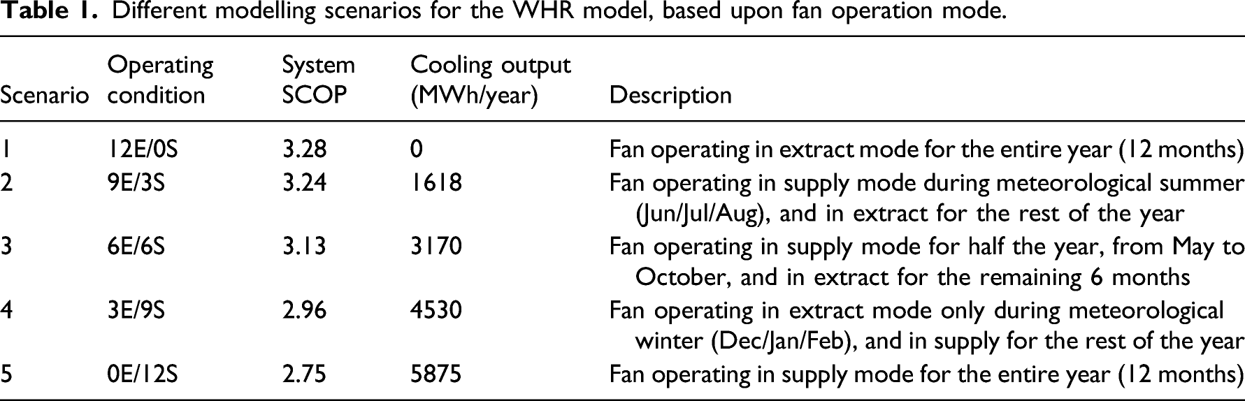
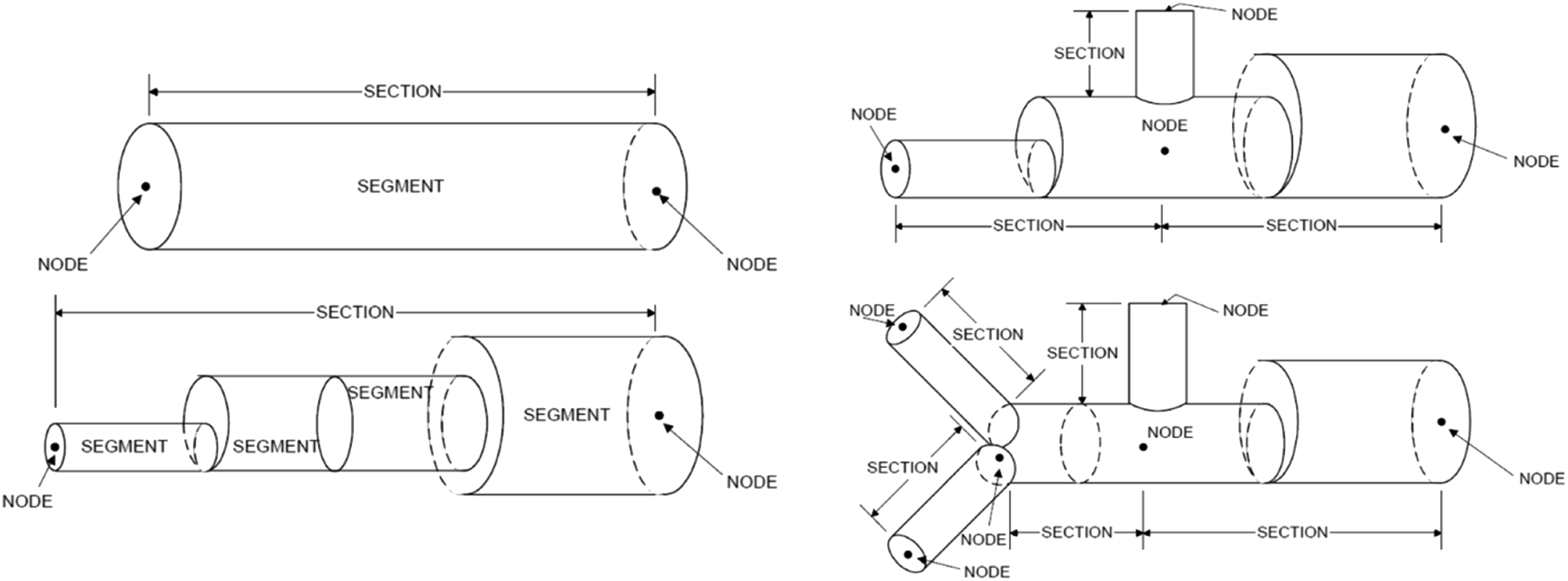
Therefore, SES can replicate the geometry of the LU and simulate the interdependent multi-factor phenomena that characterise the operation of an underground transport network. The thermodynamic simulations in SES consist of breaking down the network into smaller components of constant temperature and humidity. The heat generated within each component over time, based upon train profiles and airflow patterns, is then used to calculate energy and mass balances at nodes connecting subsequent components, whilst also taking into account the conductive heat transfer between tunnel walls and the surrounding soil.
24
This approach is used for both aerodynamic and thermodynamic calculations, and an example of how different network sections are modelled is shown in Figure 5. Examples of network sections and their components as simulated in SES.
24
The modelling approach
The results from the WHR model were used as inputs for SES, enabling the analysis of how the stations of Angel, Old Street, King’s Cross and Moorgate would respond to the provision of cooling for the Table 1 scenarios over the long term, considering the target years of 2030 and 2050. The simulations work by adjusting the dry and wet-bulb temperatures of the air that is supplied at the ventilation shaft node to the conditions predicted by the WHR model. The novelty behind this approach is enabling the use of an accurate representation of the cooling process, which is achieved with the WHR model, to investigate the effects of cooling coils on the LU environment.
The SES model developed by TfL is calibrated to utilise 2006 weather data as the basis for simulations, and the UK climate projections (UKCP) from 2009, along with train frequency profiles, are utilised to yield future platform temperatures. Therefore, the WHR model had to be run with 2006 weather data in order to provide the necessary inputs for this investigation, and the link between the WHR and SES models is illustrated in Figure 6. The cooling effect calculated by the WHR model considers both sensible and latent cooling loads associated with the heat recovery process in supply mode, and the data used for simulation are summarised in Figure 7. Schematic highlighting the inputs from the WHR model to the SES simulations. Monthly average coil duties for sensible and latent cooling, as well as air inlet and outlet temperatures calculated by the WHR model in supply mode.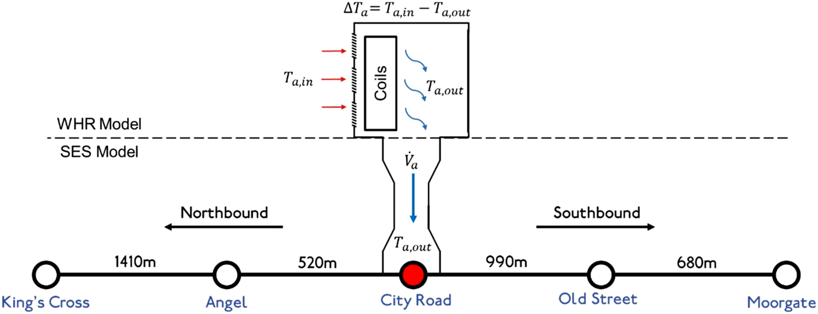
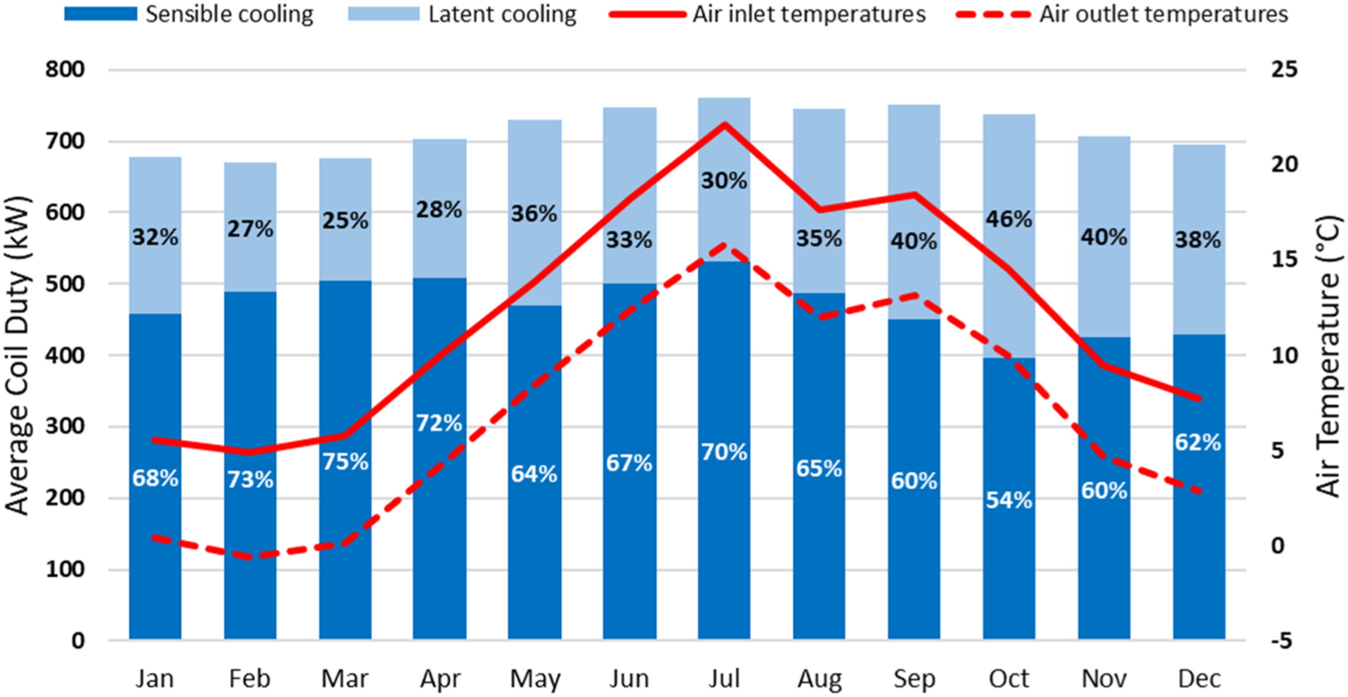
As shown in Figure 7, supply mode operation results in significant proportions of latent cooling, with an average of 34% of the total coil duty annually. This leads to a lower air temperature reduction (
Estimated platform temperatures in 2030
The outcomes from the SES analysis for the year of 2030 are illustrated in Figure 8. The results show that the scenarios involving cooling provision would lead to significant reductions in platform temperatures as opposed to year-round extract mode operation, particularly for the stations adjacent to the ventilation shaft (Angel and Old Street), as negligible reductions were observed at King’s Cross and Moorgate. The highest reductions were estimated for scenario 5, where the year-round supply of cooling could potentially reduce peak temperatures by 7.2 K at Angel and 6.3 K at Old Street. For scenarios 2, 3 and 4, which involve a combination of extract and supply modes, the average ΔTs, considering both adjacent stations, were of 1.1, 2.6 and 4.5 K, respectively, highlighting how the cooling benefit could be increased if the system operates for longer periods in supply mode. Peak platform temperatures for 2030 based upon a combination of extract and supply mode SES simulations.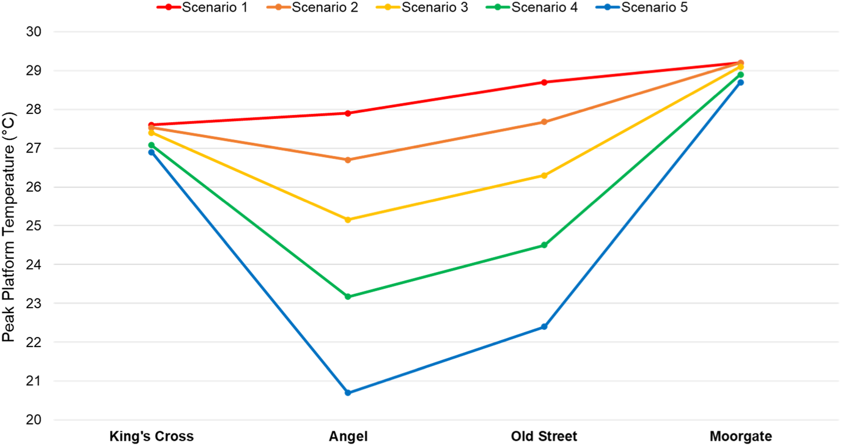
These temperature reductions might lead to several tangible benefits for LU, such as increasing the wellbeing of passengers and staff, 25 reducing risk of train delays caused by high temperatures, 8 as well as unlocking potential for service frequency and ridership to be increased. Temperature mitigation is a key enabler to service upgrades; however, the cooling benefits from the WHR system are mostly limited to adjacent stations, meaning mitigation measures would also be required at other locations in order to achieve network-wide benefits. Alternative temperature reduction measures that could be applied include regenerative braking and replacing conductor rails with new materials of lower electrical resistivity. 26
Estimated platform temperatures in 2050
The cooling benefit is also analysed in terms of the projected peak platform temperatures for the year of 2050, as shown in Figure 9. As summer represents the critical period from a cooling demand perspective, only scenario 2 was simulated in 2050, along with scenario 1, which represents a do-nothing condition in terms of cooling provision. Based upon the SCOP values reported in Table 1, scenario 2 would only cause an efficiency reduction of 1.2% compared to year-round operation in extract mode. The simulation results show that average peak platform temperatures are expected to increase by 2.7 K for the analysed stations between 2030 and 2050. These projections are associated with scenario 1, where the fan would operate solely in exhaust and no cooling would be delivered to the LU tunnels. If cooling is provided during the summer months (scenario 2), the average temperature increase by 2050 can be limited to 1.9 K against a scenario without cooling provision. If only the adjacent stations to the vent shaft are considered, where the cooling impact is highest, the rise in temperature would then be reduced to 1.3 K. For Angel station in particular, the provision of cooling during the summer months could potentially keep the evening peak temperature in 2050 within 1 K of the value estimated for 2030. Peak platform temperatures for scenario 2 in 2050, compared against 2030 and 2050 simulations for scenario 1, where no cooling is delivered.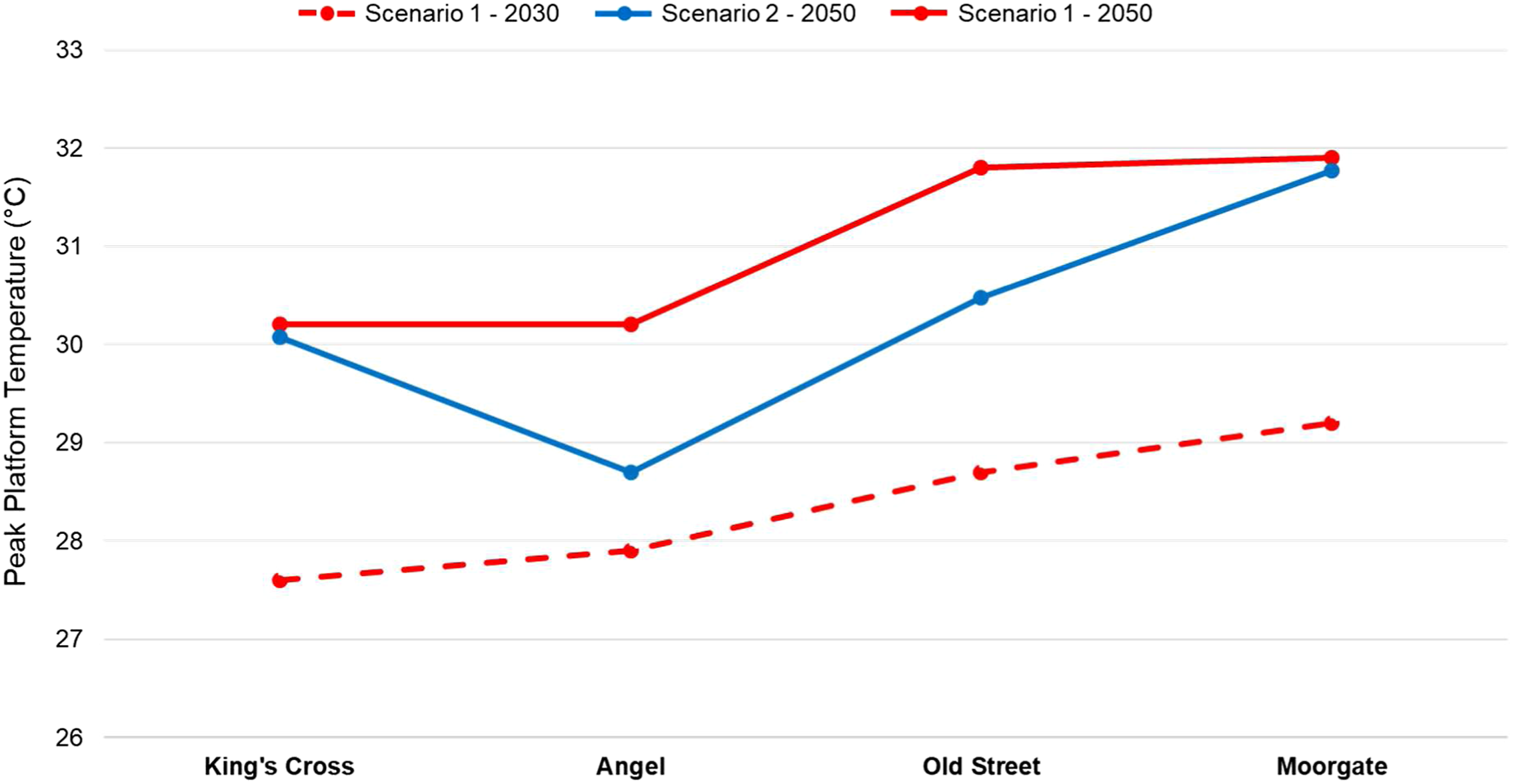
Conclusions
The results reported in this paper highlight the significant benefits that could be obtained by exploiting the cooling potential of a system that recovers waste heat from an underground railway network. The investigation was based upon a London case study; however, the approach and technology could be replicated for different locations and metro systems across the UK and abroad. In addition to avoiding the costs of cooling provision, the WHR system also has the potential to achieve considerable reductions in station temperatures, improving the thermal environment of the metro system and reducing the risk of issues associated with heat stress. A novel approach has been developed, combining EES and SES models, in order to estimate the impacts of cooling coils on railway tunnels with greater accuracy, considering both latent and sensible cooling effects. Modelling results indicate that peak temperature reductions of up to 7.2 K could be achieved at adjacent stations in 2030, depending on how the WHR system is operated.
One risk identified regarding supply mode operation is the reduction of system efficiency, as lower temperature air is used as the heat source. This could increase running costs for system operators, and a balance between cooling and heating benefits must be sought. If cooling were only provided during the summer, it would still be possible to limit the increase in platform temperatures whilst minimising impacts on system SCOP. Previous economic analyses showed how the price disparity between electricity and natural gas in the UK is still a major barrier to the development of WHR systems, particularly from a heating perspective. Therefore, it is expected that future policy can provide much needed support for waste heat and heat networks, allowing them to play their role in the decarbonisation of heat, whilst also enabling secondary benefits to be exploited, thus maximising the efficiency and feasibility of such systems.
Footnotes
Acknowledgements
The authors would like to express their gratitude for the support received from Transport for London, London South Bank University and the Engineering and Physical Science Research Council (EPSRC) through project LoT-NET. The authors are also grateful to the London Borough of Islington for their support in providing valuable information for this project.
Declaration of conflicting interests
The author(s) declared no potential conflicts of interest with respect to the research, authorship, and/or publication of this article.
Funding
The author(s) disclosed receipt of the following financial support for the research, authorship, and/or publication of this article: This work was partially supported by the Engineering and Physical Science Research Council (EPSRC) through project LoT-NET - Low Temperature Heat Recovery and Distribution Network Technologies [EP/R045496/1].