
Abstract
Additive manufacturing (AM) is increasingly employed in the development of 3D-printed wearables, including medical wrist supports, textiles, and protective garments. While the general tribological behavior of 3D-printed components has been widely studied, limited research has focused on the friction behavior of 3D-printed wearables when in contact with human skin, which is a crucial factor for improving wearer comfort by minimizing local skin friction. This study, therefore, investigates the influence of material type, manufacturing technology, and print parameters of 3D-printed textiles on frictional behavior against skin. Specimens were fabricated using three AM technologies: material extrusion (MEX), vat photopolymerization (VATP), and powder bed fusion (PBF). Each technology employed various materials and print parameters, specifically layer thickness (ranging from 0.05 to 0.3 mm) and print orientations (horizontal and vertical). Friction was measured using a custom-built handheld device at the interface between 3D-printed specimens and two surrogate skin models: lorica (representing the dorsal forearm) and silicone (representing the chest). The results revealed that friction was significantly influenced by both layer thickness and print orientation. For MEX specimens, acrylonitrile butadiene styrene, acrylonitrile styrene acrylate, and polycarbonate showed the highest friction, while for VATP, durable resin resulted in the highest friction coefficient. In contrast, PBF specimens exhibited very similar frictional behavior. Regarding layer thickness, higher values consistently resulted in the highest friction coefficients, regardless of manufacturing method or material type. These findings provide valuable insights for designers and engineers seeking to optimize the comfort of 3D-printed wearables, guiding the selection of suitable AM processes and parameters for products intended for direct skin contact.
Additive manufacturing (AM) is defined as a process of joining materials to fabricate parts directly from 3D model data, typically layer by layer, in contrast to subtractive and formative manufacturing technologies. 1 The American Society for Testing and Materials classifies AM into seven primary technologies: vat photopolymerization (VATP), powder bed fusion (PBF), material extrusion (MEX), material jetting, binder jetting, sheet lamination, and directed energy deposition. 1 The rapid adoption of AM has led to its widespread application across various industries, including electronics,2,3 aerospace, 4 and biomedical. 5 Moreover, 3D-printed wearables have garnered increasing attention due to their advantages such as design flexibility, geometric complexity, enhanced functionality, and sustainable manufacture.6 –9
Due to the advantages of AM in efficiently producing small-scale objects compared to traditional methods, the use of AM for 3D-printed wearables has also gained popularity in the fashion and jewelry industries. While initially relying on polymer materials, the material scope has since expanded to include metals such as stainless steel, bronze, and even precious metals like gold. In addition to the direct printing of final products such as 3D-printed earrings, AM is also employed in the production of casting molds, including master models used in conventional manufacturing processes. 10 Given the precision required in fashion and jewelry production, the most commonly utilized AM technologies in these industries are VATP 11 and PBF. 12 MEX has also been adopted in such applications, primarily due to its lower cost and user-friendly operation. 13
The design and fabrication possibilities of 3D-printed wearables have also expanded to 3D-printed textiles. The first seamlessly manufactured 3D-printed textile concept was introduced by Bingham et al. using selective laser sintering (SLS), a PBF method. 14 Since then, researchers have explored various 3D-printed textile structures, including flexible fabric forms that resemble knitted or woven materials. For example, Beecroft produced several knit-based textile structures such as single-layer and tubular forms from polyamide (PA) 12 powder utilizing SLS. 15 Melnikova et al. developed and investigated lace-structure fabrics made from polylactic acid (PLA) employing MEX. 16 Recent trends have also emerged in protective textiles, such as 3D-printed body armor fabricated from PA2200 using SLS 17 and from polycarbonate (PC) utilizing MEX. 18 Moreover, the adoption of AM in the wearable industry has also been recognized by major sport brands like Nike and Adidas, which have incorporated 3D printing into the production of footwear and accessories. 19
Beyond fashion and textiles, 3D-printed wearables have also found applications in the medical field. For example, Paterson et al. demonstrated the suitability of the fabrication of wrist splints fabricated via various AM processes and materials, including PA2200 for PBF, acrylonitrile butadiene styrene (ABS) for MEX, and resins for VATP. 20 Their results indicated that MEX was the least suitable process for upper extremity splinting, while PBF and VATP showed greater potential for future clinical use. Further demonstrations also include the fabrication of ankle braces from PLA using MEX. 21 Similarly, Philips et al. fabricated ankle braces from PA11 using SLS and multi jet fusion (MJF), a PBF technology. 22 They demonstrated that PBF methods exhibit superior mechanical properties compared to MEX and VATP.
As seen, several AM techniques are widely used for the production of 3D printed wearables, particularly VATP, PBF, and MEX technologies. These methods are selected based on their process-specific advantages. For instance, VATP is preferred when high resolution and fine detail are essential; PBF is commonly used for fabricating complex geometries and high-strength components; and MEX is favored for its low cost and ease of accessibility. Regarding materials, polymers, resins, and powders are the primary feedstock used in 3D-printed wearables, with each technology favoring different material types. 23 These material–process combinations result in distinct surface and mechanical properties such as roughness, moisture absorption, hardness, and stiffness, 8 which directly influence the comfort and frictional characteristics of the 3D-printed wearables.
While some studies have directly explored the tribological behavior of 3D-printed parts,24,25 a greater focus has been placed on their surface and mechanical properties. For instance, several researchers have investigated the effects of various printing parameters on the surface roughness and hardness of parts produced using VATP.26,27 In the case of MEX parts, a more extensive body of literature is available. For example, various studies have evaluated the surface roughness and quality of materials such as PLA, ABS, PC, polyethylene terephthalate glycol (PETG), thermoplastic polyurethane (TPU), and acrylonitrile styrene acrylate (ASA).28 –31 Additionally, properties including hardness, wear resistance, and stiffness have been assessed for common MEX materials like PLA, ABS, and ASA.32 –34 Furthermore, studies have examined the water absorption and hydrophilicity of MEX materials, including ABS, PLA, PC, and PETG, to evaluate their suitability, as wicking is an important phenomenon for wearable applications.35 –37 In terms of PBF technologies, most research compares the properties of parts manufactured via SLS and MJF, as these processes are similar in nature. For example, the elasticity of PA12 parts produced by SLS and MJF has been compared, with SLS samples exhibiting stiffer behavior while showing similar surface roughness to MJF samples.38,39 Similarly, mechanical properties such as the elastic modulus of SLS and MJF-printed PA12 samples have been evaluated. 40 To further understand the application of PBF technologies in 3D-printed wearables in terms of wicking, the water immersion properties of SLS-manufactured PA12 were investigated. 41 Additionally, the effect of surface treatments, such as antibacterial coatings, on the usability of PA12 orthoses produced by MJF and SLS was examined. 42
Despite these technical investigations, the user experience, particularly in terms of skin interaction, remains underexplored. This is due to the unpredictable tribological behavior of 3D-printed surfaces depending on the print parameters and material type, 33 which exhibits highly non-linear responses to variations in 3D printing parameters. Therefore, to further understand the use of 3D-printed wearables in the real-world environment, understanding the interaction between 3D-printed materials and human skin becomes essential, especially given the complex and variable nature of skin. This is because when in contact with 3D-printed wearables, the skin, being a sensitive and complex organ, requires thorough investigation to avoid discomfort such as dermatitis, irritation, abrasions, and blisters.43 –45 However, there is very limited research specifically examining their interaction with human skin. For example, Kasar et al. investigated the wet and dry tribological performance of 3D-printed TPU and PA against a water-responsive skin model, reporting higher coefficient of friction (COF) under wet conditions. 46 Similarly, Vilhena and Ramalho examined the grip characteristics of patterned 3D-printed PLA and polydimethylsiloxane (PDMS) on two different body regions (finger pad and volar forearm) under varying moisture conditions. Their findings showed that PDMS exhibited a lower COF than PLA, attributed to differences in material properties such as the elastic modulus. 47
The comfort and wearability of 3D-printed wearables are largely influenced by three key factors: material selection, manufacturing technology, and print parameters. These factors collectively determine the mechanical and thermal properties of the final product,48 –51 which directly affect its interaction with skin. This is particularly important for 3D-printed wearables that contact sensitive regions around the body, such as the neck or chest, where friction at the skin–3D-printed wearable interface can significantly impact user comfort.52 –54 In addition to the material and process used, print parameters, especially layer thickness and layer orientation, have been shown to significantly influence the surface finish of 3D-printed parts,55 –57 which have the potential of affecting the frictional behavior during skin contact as a result of the changes in the contact area and surface roughness of 3D-printed wearables.
As noted, the current literature on the frictional interaction between skin and 3D-printed parts remains limited, highlighting the need for a comprehensive investigation. This research, therefore, aims to address this gap by examining the frictional behavior between skin and 3D-printed wearables, with a specific focus on the effects of material type, manufacturing technology, and print parameters, specifically layer thickness and print orientation. To the authors’ knowledge, this is the first study to evaluate the COF between skin and 3D-printed parts across a broad spectrum of AM conditions. A custom-made friction measurement device was employed to measure the COF between skin surrogates and 3D-printed samples. While lorica and silicon surrogate skins were used as skin simulants, 3D-printed wearable samples were fabricated using MEX, VATP, and PBF technologies, each manufactured with varying layer thicknesses and print orientations.
Method
Measurement device
A custom-made and portable handheld friction device was used to measure the friction between the surrogate skins and 3D-printed materials. The device is specifically designed to quantify the COF between skin and various materials (e.g., cotton, polyester, silk). It is equipped with 100 g cantilever straight-bar mini load cells (±0.1%), which independently capture both normal and frictional forces. During testing, the device is pressed against a specific body region, while the probe moves vertically at a constant speed. This motion stretches an internal spring, allowing the load cell to record the normal force applied perpendicularly to the skin. As the probe contacts the surface, a frictional force is generated and measured simultaneously. Both normal and frictional forces are captured in real time. The COF was calculated using custom-built software developed in LabVIEW. Further technical details and the measurement mechanics of the device are explained by Temel et al. 58
Test specimen design and fabrication
The shape of the 3D-printed test specimen was knob-like as per the custom-made friction device requirement. This was designed using SolidWorks® (Dassault Systemes, Waltham, MA, USA) based on the details as illustrated in Figure 1.
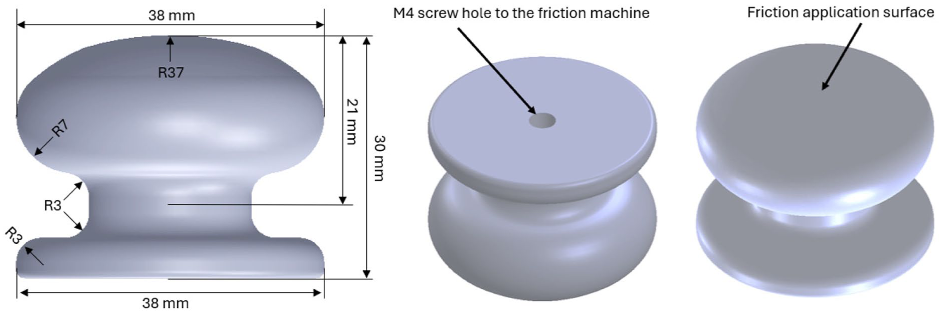
Details of the custom-made friction device probe.
The selection of 3D printing processes and materials was guided by a comprehensive literature review, with the aim of reflecting the most widely adopted technologies in 3D-printed wearable applications. The three AM technologies chosen, MEX, VATP, and PBF, represented distinct classes of AM processes due to their accessibility, material properties, and resolution capabilities. Due to machine-specific constraints, not all technologies were applied across every thickness. Layer thicknesses were selected based on the capabilities of each printer and material combination, and infill rate and pattern were 100% and linear, respectively, while other print parameters were set to the default or recommended values provided by the manufacturer. This approach ensured reliable output and consistent print quality within the optimal operating range of each technology.
For materials utilized in MEX technology, PLA, ABS, ASA, PC, PETG, TPU95A, and TPU85A (namely NinjaFlex) were selected. MEX specimens were fabricated at four different layer thicknesses of 0.05, 0.1, 0.2, and 0.3 mm using a Prusa i3 MK3S+ 3D printer (Prusa3d, Czech Republic). Moreover, for VATP, a Formlabs Form 2 (Formlabs, USA) printer was used, employing three materials: clear, durable, and tough resins, which are the Formlabs OEM (original equipment manufacturer) products. VATP specimens were manufactured at two thickness levels: 0.05 and 0.1 mm. Lastly, PBF specimens were manufactured at 0.1 mm thickness from PA12 using two different PBF technologies with a comparison purpose: SLS on an EOS P100 printer (EOS, Germany) and MJF on an HP 5210 Pro printer (HP, USA).
Regardless of the manufacturing method, all knob-shaped specimens were manufactured in two print orientations: horizontally and vertically to the build platform. This is because other angled print orientations, such as 30° and 45°, create uneven stairstep patterns on the friction surface. This could make the friction more complicated to investigate because the roughness becomes irregular across the surface, the contact area varies with sliding direction, and the layer alignment is neither fully parallel nor perpendicular to sliding. For the horizontal direction, each part was printed starting from the bottom of the part, while for the vertical direction, each part was printed starting from the side of the bottom, as illustrated in Figure 2. Some examples of the manufactured specimens using MEX technology are illustrated in Figure 3.
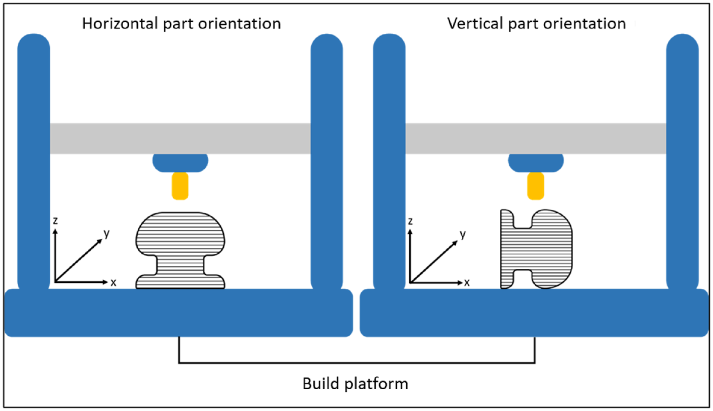
Horizontal part orientation (left) and vertical part orientation (right).
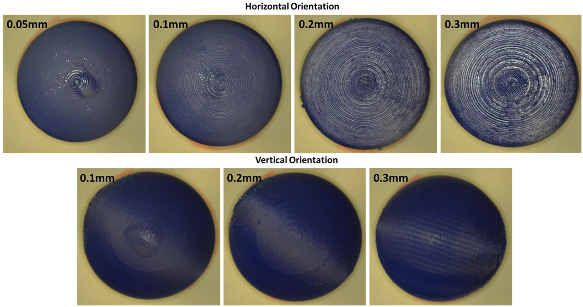
High-resolution pictures of ASA specimens manufactured at different layer thicknesses and part orientations using MEX technology.
Contact surfaces
In this study, two surrogate skins, lorica (Ehrlich-Leder, Germany) and silicon (Reelskin, UK), were considered as the skin. These were chosen based on the information gained from the literature.58,59 While the lorica surrogate skin represented body regions with low skin COFs, such as the dorsal forearm and lower back, the silicon surrogate skin represented body regions with high COFs, such as the neck and the upper and lower chest.53,54 The length and width of the surrogate skins were fixed at 100 × 100 mm.
It is important to acknowledge the inherent complexities of testing with human participants, particularly in achieving consistent material properties and environmental control. This is because human skin exhibits considerable variability in biomechanical, structural, and sensory characteristics due to factors such as age, sex, ethnicity, hydration level, and underlying dermatological conditions. Beyond these physical differences, responses to tactile stimuli can be shaped by subjective perception, cultural background, and prior experience. Moreover, friction testing of 3D-printed parts with human participants also presents practical challenges such as recruitment, standardization of test protocols, and participant fatigue, as well as potential discomfort. These sources of variability can complicate data interpretation and limit comparability between individuals.
Recognizing these challenges provides important context for the methodological choice to use surrogate skins in this study. Surrogate skins were utilized to ensure reproducibility and control over experimental conditions, particularly given the lack of prior data on the frictional behavior of 3D-printed surfaces and the unpredictable interactions they may produce with biological skin.
Experimental setup
The experimental setup, as illustrated in Figure 4, consisted of the friction device, contact material (3D-printed specimens), and contact control surface (silicon and lorica surrogate skins). Moreover, a custom-made frame was used for holding the friction device to ensure stability during friction measurements while the probe moved over the contact surface.
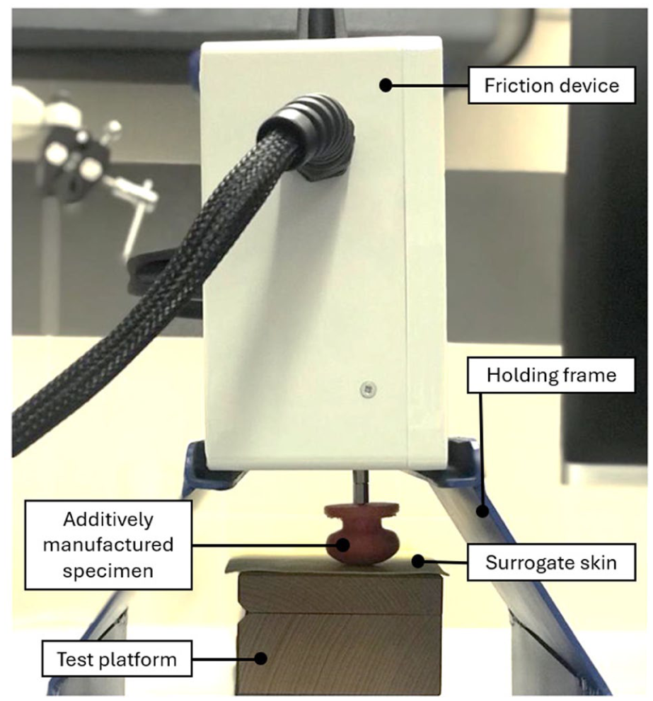
Experimental setup for friction measurement in the skin and 3D-printed specimen.
Horizontally manufactured specimens were applied to surrogate skin in a single direction, as shown in Figure 5(a), since the frictional response is direction-independent due to the circular print pattern. Vertically manufactured specimens were applied to the surrogate skins in two orientations. For the vertical parallel orientation, the layers of the specimen and sliding direction were parallel to each other (Figure 5(b)), while for the vertical perpendicular orientation, the layers of the specimen and sliding direction were perpendicular to each other (Figure 5(c)).
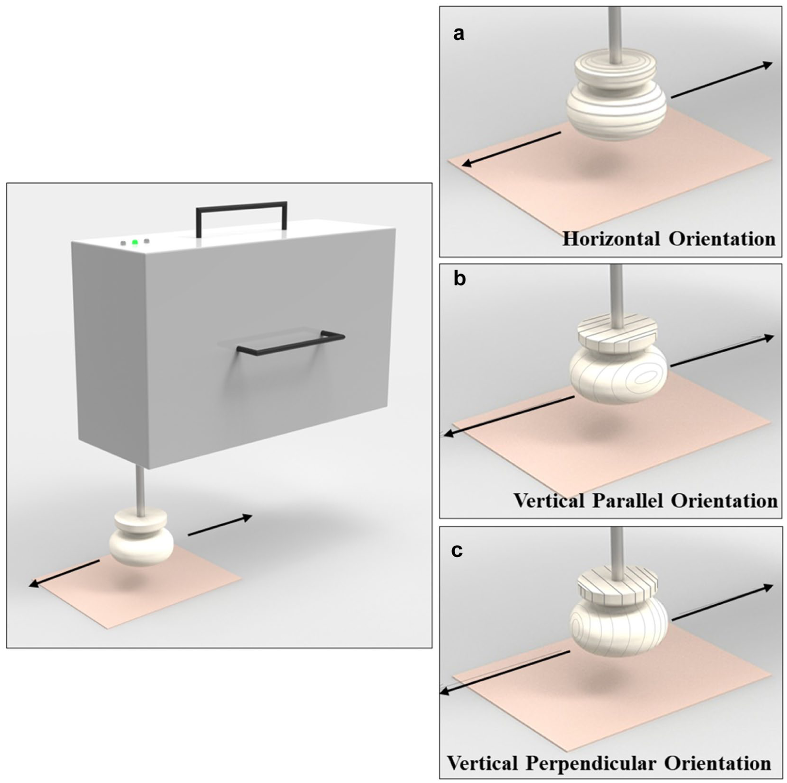
Application directions of the specimens.
Data collection
All measurements were conducted at an environmental temperature of 25°C and 50% relative humidity. The first specimen was attached to the friction device, and the device was placed in the holding frame. The control surface material was then fastened to the test platform and placed beneath the probe, and the applied force was adjusted by the custom-developed tracking software controlled on a personal computer. Upon this, the friction device measured both static and dynamic COFs. This process was repeated for each specimen and each surrogate skin. In total, 612 specimens were tested. A normal load of 2 ± 0.05 N was applied to control surfaces with a 0.04 m/s velocity over a 40 mm moving surface. A 0.04 m/s velocity was used because it is approximately in the middle of the pleasantness range. 60 The overview of data collection is summarized in Figure 6.
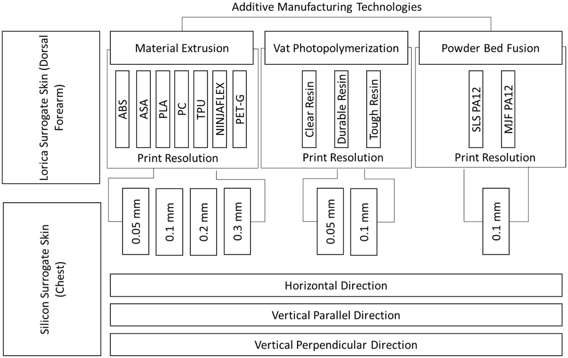
An overview of AM technologies, materials, layer thicknesses, and application contact surfaces used in this study.
Results
MEX specimens
The results showed that the skin friction coefficient of MEX-manufactured parts depended on the material type, layer thickness, and part orientation, as summarized in Figure 7.
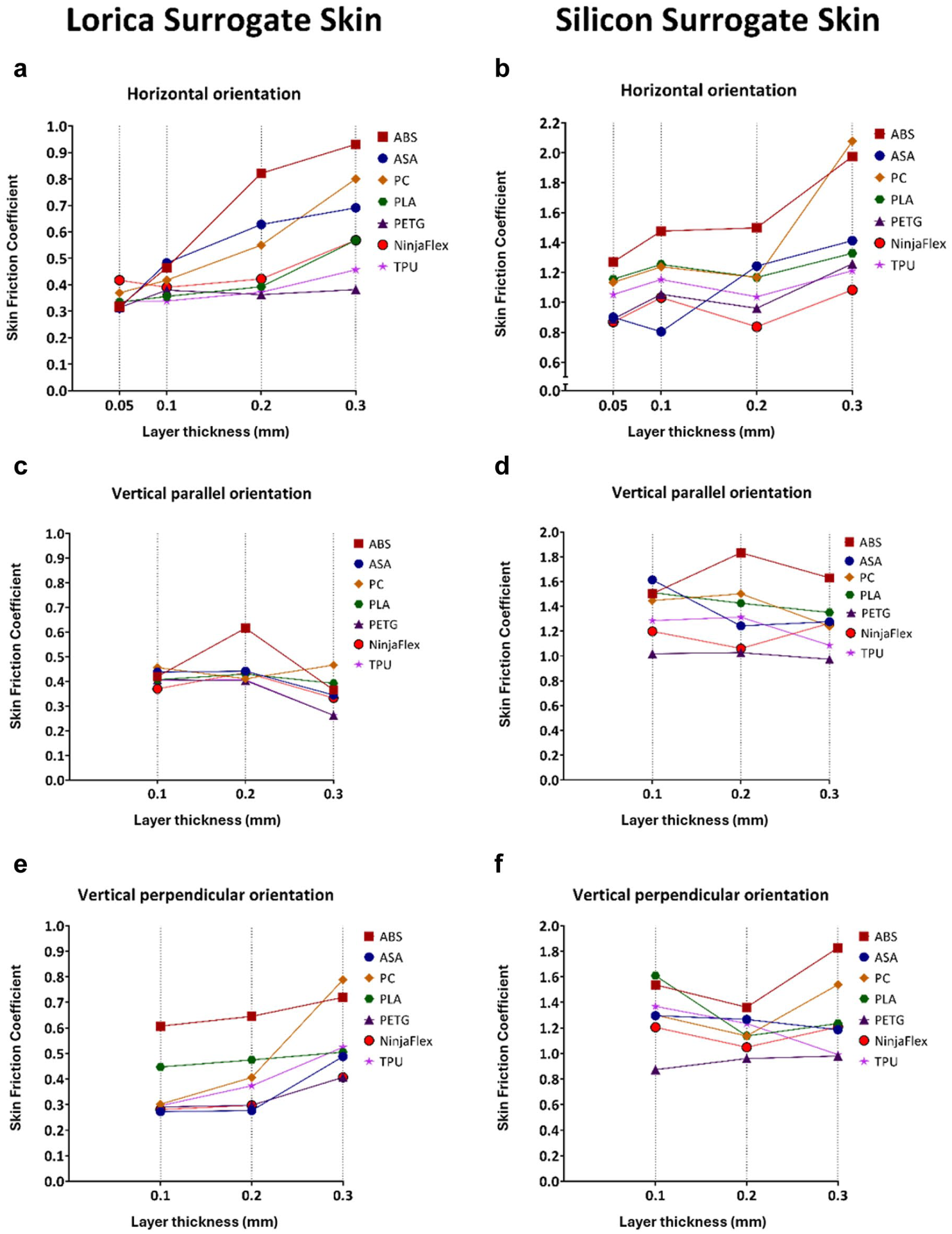
The relationship between layer thickness of MEX specimens and skin friction coefficient when specimens were applied on lorica and silicon surrogate skins.
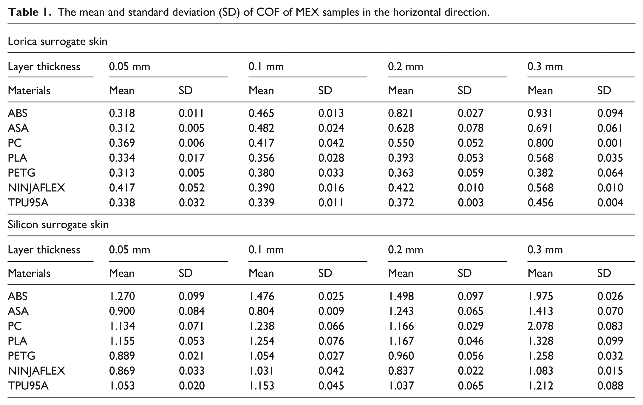
The COF increased with the increasing layer thickness when specimens interacted with the lorica surrogate skin in the horizontal orientation, as shown in Figure 7(a). The highest skin friction coefficient was observed at the greatest layer thickness (0.3 mm), with ABS specimens generally exhibiting the highest COFs across all print resolutions, except at a 0.05 mm layer thickness. Similarly, the COF increased with increasing layer thickness when specimens were tested against silicone surrogate skin in the horizontal orientation, as presented in Figure 7(b). ABS mostly exhibited the highest skin friction coefficients across different layer thicknesses, except for the 0.3 mm layer thickness, where PC showed the highest value. The detailed results of the MEX samples in the horizontal direction are presented in Table 1.
The mean and standard deviation (SD) of COF of MEX samples in the horizontal direction.
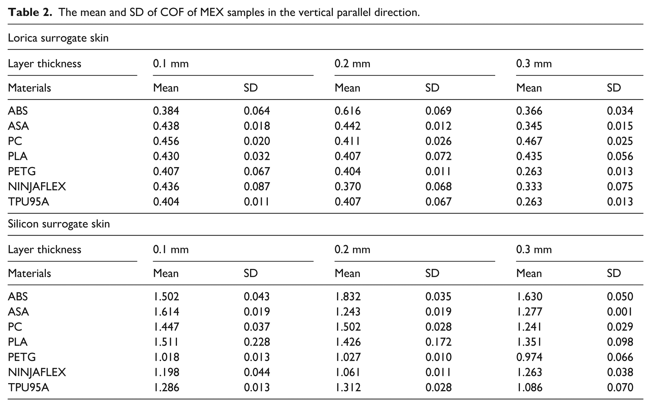
In contrast, the results from the vertical parallel orientation (Figure 7(c)) demonstrated that the COF decreased with increasing layer thickness when the specimens were in contact with the lorica surrogate skin. Specimens manufactured with 0.1 and 0.2 mm layer thickness settings exhibited similar COFs, both higher than that of the 0.3 mm specimens, except for ABS. The ABS specimens with 0.2 mm layer thickness exhibited higher COFs than their 0.1 and 0.3 mm counterparts. For silicone surrogate skin in the vertical parallel orientation, the results overall showed that increasing layer thickness led to a decrease in the COF, as presented in Figure 7(d). The COF of PETG specimens remained relatively constant across all three layer thicknesses. The detailed results of the MEX samples in the vertical parallel direction are presented in Table 2.
The mean and SD of COF of MEX samples in the vertical parallel direction.
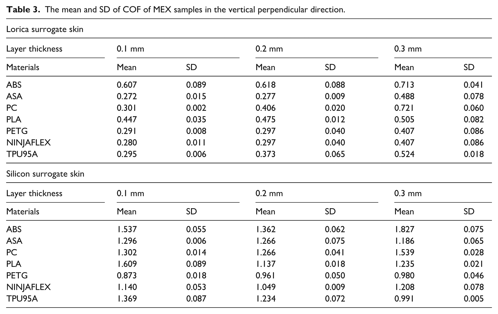
In the vertical perpendicular orientation, specimens manufactured with a 0.3 mm layer thickness exhibited greater COFs than those printed with 0.1 and 0.2 mm layer thicknesses when tested on the lorica surrogate skin, as illustrated in Figure 7(e). Similarly, a 0.3 mm layer thickness resulted in increased skin friction coefficients when tested on silicone surrogate skin, except ASA material, as shown in Figure 7(f). The detailed results of the MEX samples in the vertical perpendicular direction are presented in Table 3.
The mean and SD of COF of MEX samples in the vertical perpendicular direction.
VATP specimens
The resin material, layer thickness, and part orientation influenced the COF between the skin and VATP-manufactured specimens, as detailed in Figure 8.
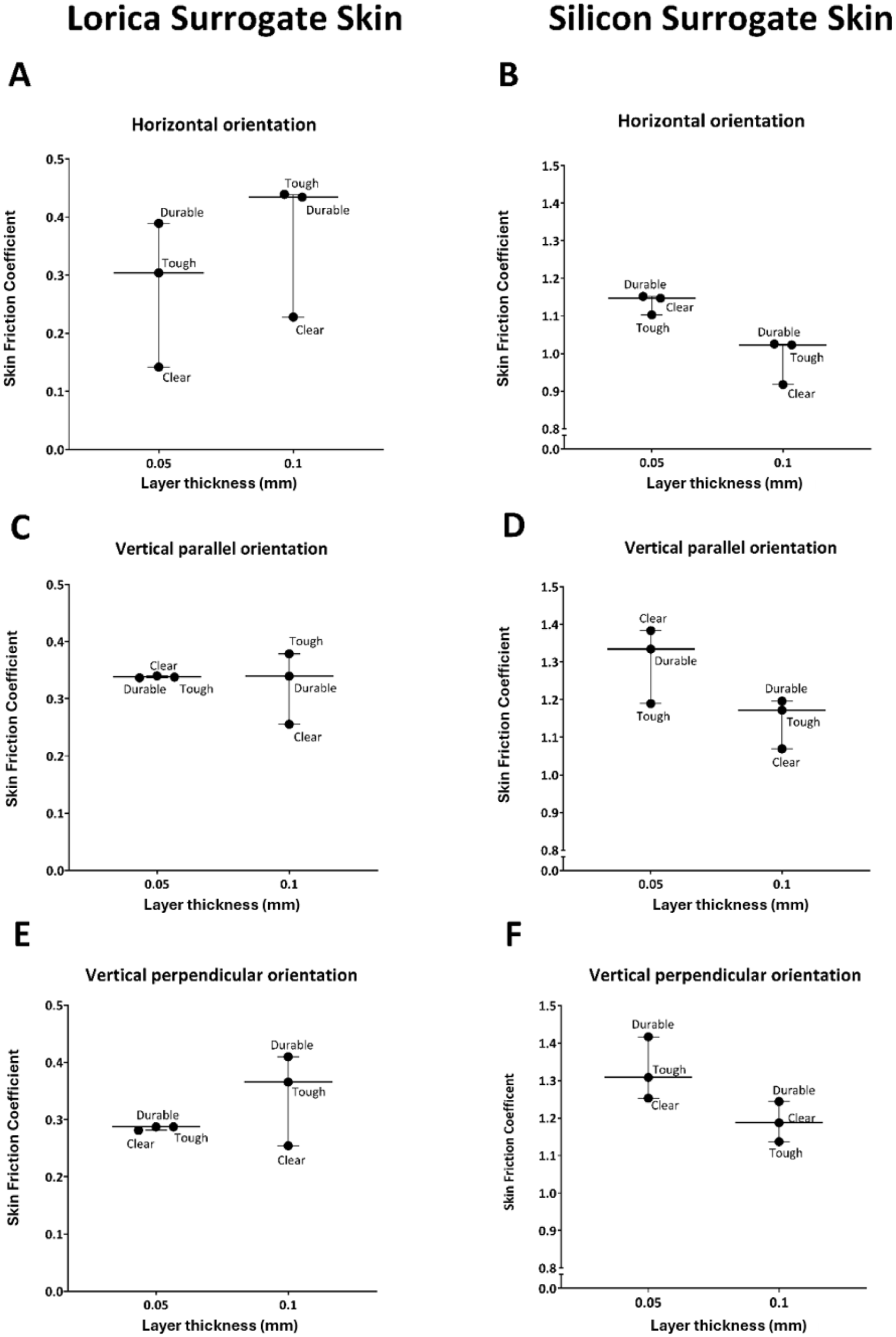
Relationship between layer thickness of VATP-manufactured specimens and skin friction coefficient when specimens were applied on lorica and silicon surrogate skins.
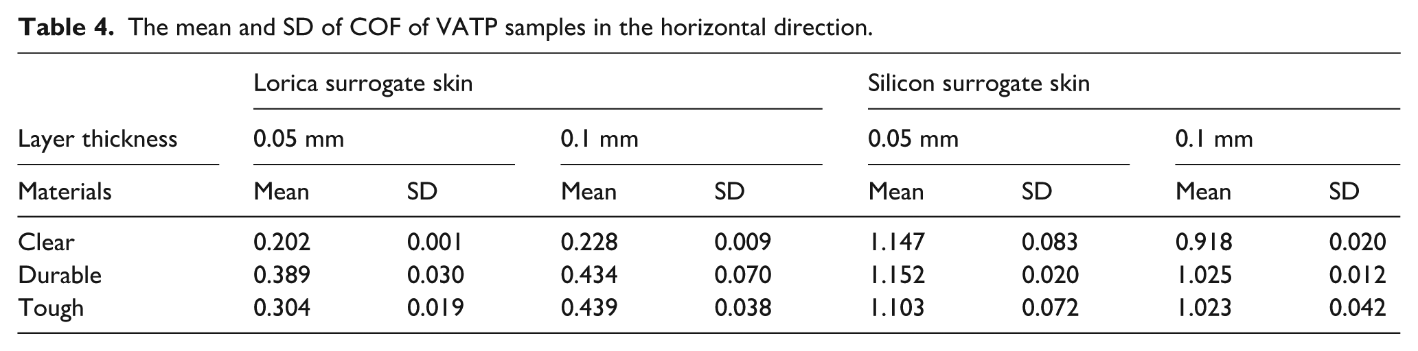
Specimens manufactured with high-resolution (0.05 mm layer thickness) from durable resin and low-resolution (0.1 mm) from tough and durable specimens exhibited the highest COF when applied to the lorica surrogate skin at the horizontal part orientation (Figure 8(a)). In contrast, for silicon surrogate skin at the horizontal orientation, high-resolution (0.05 mm) from durable and clear resin specimens, along with low-resolution (0.1 mm) from tough and durable specimens, displayed the highest COFs (Figure 8(b)). The detailed results of the VATP samples in the horizontal direction are presented in Table 4.
The mean and SD of COF of VATP samples in the horizontal direction.
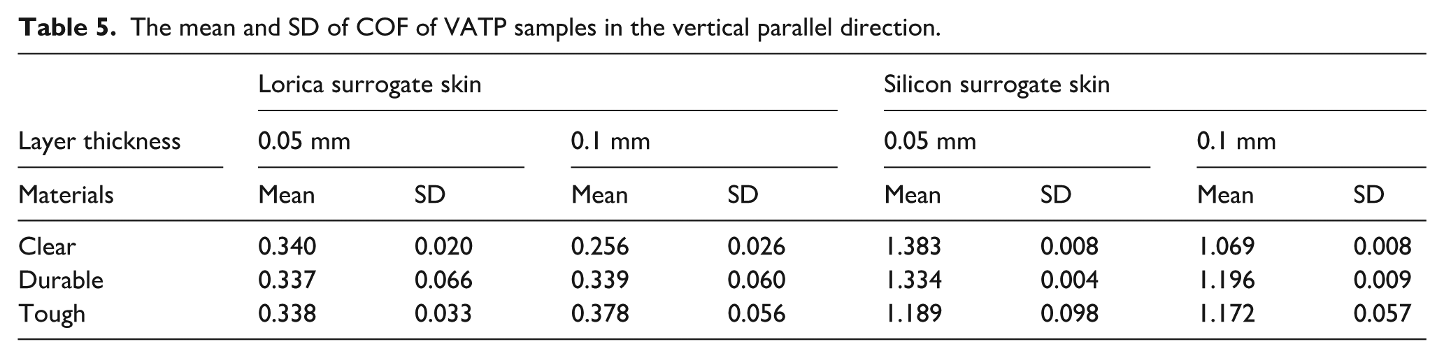
In the vertical parallel orientation, specimens printed at a 0.05 mm layer thickness had similar COFs. However, specimens manufactured at a 0.01 mm layer thickness showed variations, with tough resin specimens exhibiting the highest COF on the lorica surrogate skin (Figure 8(c)). Moreover, when applied to silicon surrogate skin, parts manufactured from clear and durable resin demonstrated the highest COFs at 0.05 and 0.1 mm layer thicknesses, respectively (Figure 8(d)). The detailed results of the VATP samples in the vertical parallel direction are presented in Table 5.
The mean and SD of COF of VATP samples in the vertical parallel direction.
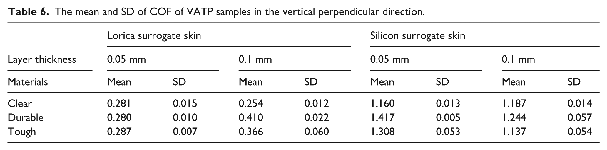
In the vertical perpendicular orientation, specimens manufactured at a 0.05 mm layer thickness had comparable COFs when applied to the lorica surrogate skin (Figure 8(e)). Additionally, when tested on silicon surrogate skin, parts manufactured from durable resin showed the highest COF (Figure 8(f)). The detailed results of the VATP samples in the vertical perpendicular direction are presented in Table 6.
The mean and SD of COF of VATP samples in the vertical perpendicular direction.
PBF specimens
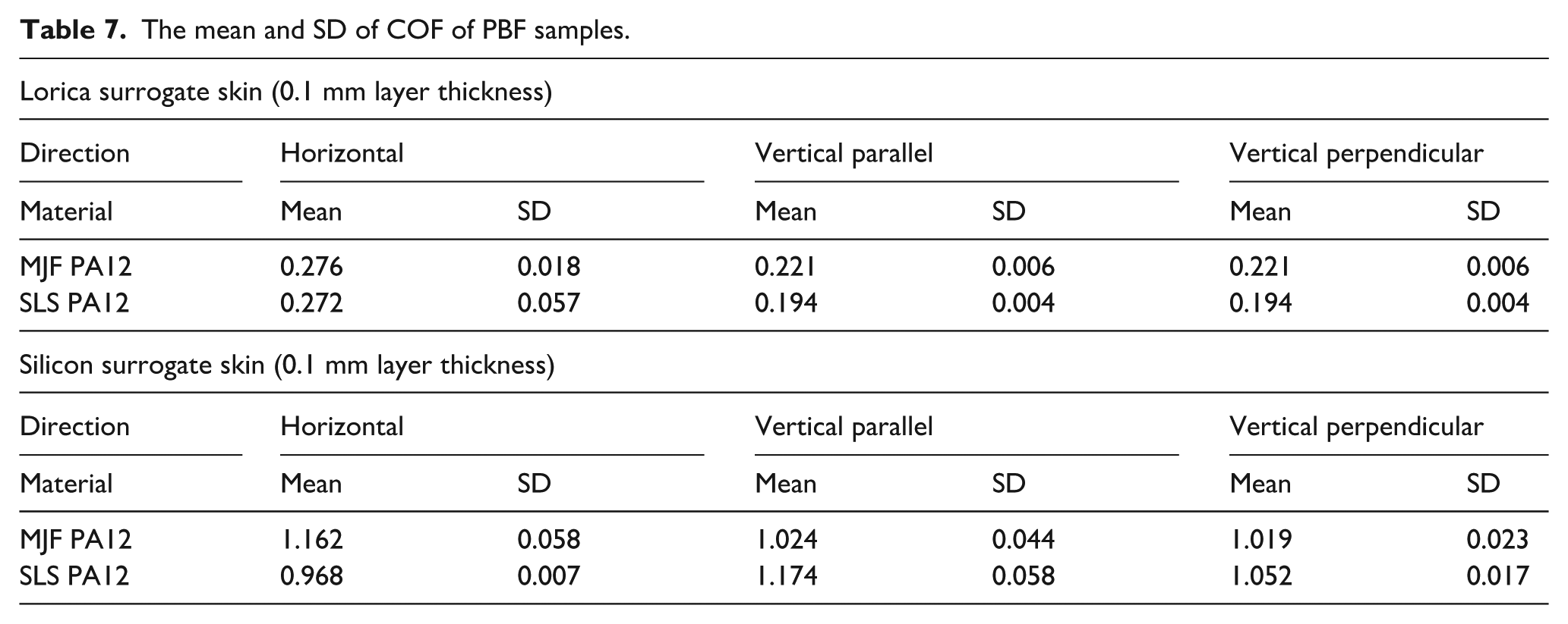
The detailed results for the friction between skin and PBF-fabricated parts are presented in Table 7. It was found that PBF specimens manufactured from the same material using different methods exhibited similar COFs when tested on the lorica surrogate skin, as shown in Figure 9(a). However, differences emerged in the horizontal and vertical parallel orientations when tested on silicon surrogate skin. In these cases, SLS PA12 showed a higher COF compared to MJF PA12, as shown in Figure 9(b).
The mean and SD of COF of PBF samples.
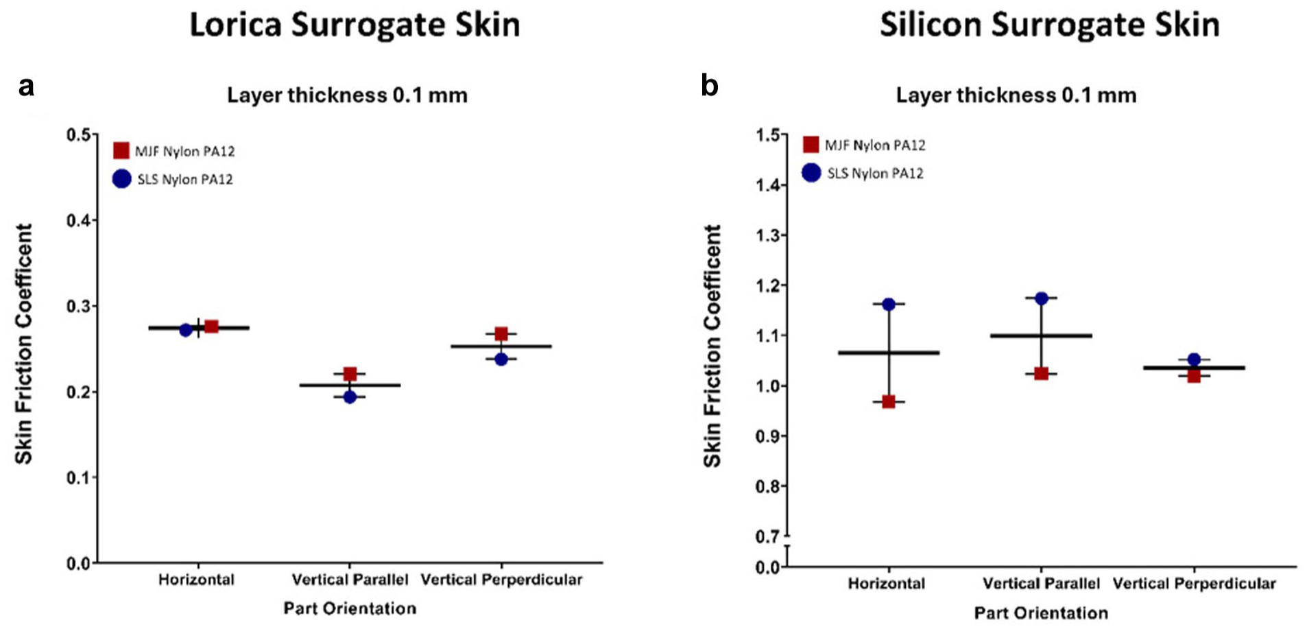
Relationship between part orientation of PBF-manufactured specimens and skin friction coefficient when specimens were applied on lorica and silicon surrogate skins.
Discussion
This study offers a novel and comprehensive analysis of the frictional behavior of 3D-printed surfaces when in contact with human skin, which is largely overlooked in the current 3D-printed wearable research. Unlike prior studies that focus on surface characteristics or indirectly related mechanical properties, this work directly investigates friction coefficients at the interface between skin and 3D-printed specimens, using two widely accepted surrogate skins: lorica and silicone. It has systematically evaluated multiple 3D printing technologies (MEX, VATP, and PBF), a range of materials, and key printing parameters, specifically layer thickness and print orientation within a unified framework. The results have highlighted how these variables influence skin-part friction, offering practical guidance for designing more comfortable, skin-friendly 3D-printed wearables and addressing a significant gap in the literature. The previously presented findings are discussed in the context of the study’s threefold objectives, as follows.
Effect of material type on COF
Materials that come into contact with skin influence the skin friction coefficient.61 –65 However, to the best of our knowledge, there has been no prior research to comprehensively evaluate the skin friction coefficient of the commonly used 3D-printing materials. Differences in COFs were observed across the range of test materials interacting with lorica and silicone surrogate skins. More specifically, among MEX materials, ABS, ASA, and PC materials exhibited higher COFs than those of PLA, PETG, TPU95A, and TPU85A. This suggests that mechanical properties such as hardness and stiffness could influence the friction coefficient.
In terms of VATP materials, the results showed that resin type affected the COF as a result of the interaction between skin and 3D-printed VATP parts. Durable resin exhibited higher friction compared to tough and clear resins due to its lower stiffness. The low level of stiffness possibly contributed to an increased skin friction coefficient. This outcome aligns with previous findings suggesting that mechanical properties, such as stiffness, can influence the friction coefficient.62,65 –67
The effect of materials used in PBF technology depends on the contact surface. MJF PA12 and SLS PA12 exhibited similar COFs when tested against the lorica surrogate skin. However, these showed differing COFs when applied to the silicone surrogate skin, with SLS PA12 demonstrating a higher COF than MJF PA12. This suggests that the friction behavior of PBF materials can vary depending on the type of representative body site or contact surface material interacting with the 3D-printed parts.
Findings regarding the influence of material type in 3D-printed components in relation to the skin friction coefficient indicate that careful consideration should be given to the specific body region of contact when selecting materials for 3D-printed textiles.
Effect of layer thickness on COF
3D-print parameters affect the final properties of material types, such as the mechanical properties, surface finish, and dimensional accuracy,48,68 –70 all of which are important factors to consider when creating a product that interacts with the skin.71,72 However, to the best of our knowledge, no research has been undertaken to evaluate the impact of layer thickness on skin friction coefficients, which is an area of importance in relation to the growing use of AM technologies for the manufacture of 3D-printed wearables.
The results of this research showed that MEX specimens printed at a 0.3 mm layer thickness exhibited higher skin friction coefficients in both the horizontal and vertical perpendicular orientations compared to those printed at 0.05 and 0.1 mm resolutions. This is likely to be due to the increased surface roughness resulting from thicker layers, which aligns with findings from previous research. 73 However, in the vertical parallel orientation, the 0.3 mm layer thickness specimens demonstrated lower friction. This may be because, in the parallel direction, the larger layer thickness creates a greater contact area with the skin. These findings suggest that the effect of layer thickness on the COF is dependent on the part orientation.
Even though using smaller values of layer thickness improves the surface quality of 3D-printed textiles, this generally results in higher manufacturing times. For example, the average manufacturing time for 0.05 mm specimens was recorded to be five times greater than that of 0.3 mm specimens. As a result, layer thickness should be determined by the product’s intended purpose. If the designer or engineer needs a material that has a smooth-to-touch feel on the skin, layer thicknesses of 0.05 and 0.1 mm in the horizontal or vertical perpendicular direction could be chosen in an attempt to minimize skin friction.
Similarly, for VATP materials, the skin friction coefficient was influenced by layer thickness. The results showed that low-resolution specimens, that is, specimens with high layer thickness, had a higher COF compared to high-resolution specimens. However, when specimens were applied to the silicon skin, high-resolution specimens, that is, manufactured at lower layer thicknesses, had a higher COF compared to low-resolution specimens. Therefore, the results indicated that the effect of layer thickness on COF depends on the contact surface. It is essential to consider the parts of the body where 3D-printed textiles could interact. The current investigation used lorica and silicon surrogate skin that had low-friction body regions such as the dorsal forearm (lorica surrogate skin), and high-friction body regions such as the chest (silicon surrogate skin). Therefore, layer thickness should be controlled by the product’s intended purpose. When VATP is used as the production process for a 3D-printed product or component that interacts with low-friction body areas such as the dorsal forearm, a layer thickness of 0.05 mm is currently recommended. However, a minimum 0.1 mm layer thickness could be used for products that may interact with body areas with high-friction areas, such as on the chest. However, investigating the texture perception of AM specimens by potential users would be beneficial for future research to gain a more comprehensive understanding of the interaction between skin and 3D-printed wearables.
Effect of part orientation on COF
The results showed that the part orientation impacted on COF; however, this impact was dependent on layer thickness. MEX specimens manufactured with 0.1 mm layer thickness at the vertical parallel orientation had a higher COF compared to the horizontal and vertical perpendicular orientations. However, specimens with 0.2 and 0.3 mm layer thicknesses at the horizontal orientation had higher COFs compared to the vertical parallel and perpendicular orientations.
For VATP, the results revealed that the part orientation affected COF; however, this effect depended on the layer thickness and contact area. Specimens manufactured with a 0.1 mm layer thickness applied on the lorica at the horizontal had higher skin friction compared to the vertical parallel and perpendicular orientations. As a result, print direction should be considered according to the preferred layer thickness, contact skin area, and material.
The results for PBF showed that the part orientation had no clear impact on the COF. A possible explanation is that products manufactured using PBF technologies have high-quality surface characteristics, with layers that are nearly invisible. This, therefore, minimizes the impact of the layer direction on the COF.
This study has two key limitations. The first is the lack of baseline data on the fundamental frictional properties of bulk materials without AM influences. Since all test specimens were additively manufactured, the effects of AM-related factors such as surface roughness, layer orientation, and anisotropy could not be separated from the material’s intrinsic friction characteristics. To properly isolate these AM-driven effects, future work should focus on the comparison of the friction behavior between traditionally manufactured and additively manufactured parts, thereby advancing the fundamental understanding of friction behavior in AM wearable applications.
Second, it focuses specifically on frictional interactions with flat, non-hairy, and dry skin surfaces as a fundamental baseline for understanding the prospective wearability of 3D-printed wearables. However, comprehensive performance evaluation must extend to additional critical factors such as geometric considerations (sharp edges, narrow gaps), user-dependent parameters (hair entrapment potential), and hygiene maintenance aspects (dirt accumulation propensity, cleanability). Such multidimensional characterization becomes particularly crucial for real-world applications where dynamic user interaction, variable environmental conditions, and long-term usability requirements must be addressed. Therefore, future investigations should also incorporate these parameters through systematic studies under more realistic use conditions.
Conclusion
With the growing interest in 3D-printed wearables, ranging from healthcare applications to textiles, there is an increasing need to evaluate how such structures affect the wearer, particularly in terms of user comfort factors such as friction. This study, therefore, examined the friction between surrogate skins and 3D-printed parts fabricated using different materials and three common AM technologies. The key findings are summarized as follows:
The COF varied depending on the specific AM materials being used. The mechanical features of the materials could impact the skin friction coefficient. Therefore, testing the COF with a greater range of materials with different material and mechanical properties, beyond the commonly used materials presented within this study, would be beneficial for future investigations in order to further understand the relationship between material characteristics and COF in a design context.
The COF varied considerably according to layer thickness and part orientation, which may also impact material use, production time, and cost. The findings from this study could be used when designing 3D-printed wearables or components that interact with human skin.
The findings from this work are intended to assist designers and engineers in selecting appropriate AM processes, materials, and manufacturing settings when developing AM parts or end-use products that will come into direct contact with the skin, specifically areas representative of the dorsal forearm (lorica surrogate skin) and chest (silicone surrogate skin). However, it is recognized that further research is needed to better understand the interaction between skin and 3D-printed products. Therefore, future studies will focus on investigating the relationship between the mechanical properties and friction behavior of 3D-printed parts across a wider range of print parameters and materials, particularly in relation to skin contact with 3D-printed end-use products.
Footnotes
Author contributions
Conceptualization: MT, UC, AL, AJ; data curation: MT; formal analysis: MT; funding acquisition: MT; investigation: MT, UC; methodology: MT, UC, AL, AJ; resources: MT, UC, AL, AJ; visualization: MT, UC; validation: UC, AL, AJ; project administration: AL, AJ; software: AL, AJ; supervision: AL, AJ; draft manuscript preparation: MT. All authors reviewed/edited the results and approved the final version of the manuscript.
Declaration of conflicting interests
The authors declared no potential conflicts of interest with respect to the research, authorship, and/or publication of this article.
Funding
The authors disclosed receipt of the following financial support for the research, authorship, and/or publication of this article: This work was financially supported by PhD scholarships from the Ministry of National Education of the Republic of Türkiye.
Data availability statement
Data will be made available upon request.