
Abstract
Real-time detection of fabric defects is a fairly critical part of industrial production. However, there are still some key issues to be solved in practical detection production, such as low detection speed and delays in traditional cloud detection. To address these issues, in this paper, a new detection network architecture, called YOLOV4-TinyS, is proposed. Firstly, the k-medoids clustering algorithm is used to improve the matching of anchor points and ground truths for datasets with great differences. Secondly, the residual structure is changed to reduce the complexity of the network structure, and a depth-separable convolution is used instead of partial convolution to improve the detection speed. Thirdly, the output feature layer is designed with shallow feature fusion to improve the location information extraction capability and use spatial attention and channel attention to improve the network efficiency. Finally, the whole network is trained and tested on four different datasets and extensive experiments show that the network has higher detection accuracy and faster detection speed compared to existing methods. Compared to the original network, YOLOV4-Tiny, the model complexity is reduced by 67.86% and the highest detection accuracy of 99.91% is achieved. Furthermore, the establishment of an efficient fabric inspection system and the validation of the method allows for the fast detection of fabric defects on conveyor belts. Thus, the proposed method has the potential to lay the foundation for the real-time detection of fabric defects and their application in industry.
Fabric is not only used in clothing, elastic bands and gloves, but also in other industries such as aerospace, military enterprises and health care.1,2 However, mechanical faults, defective yarns or oil stains on sewing machines can lead to product defects. 1 Therefore, effective inspection is necessary during the production process. For some brands, a defective product can have a negative impact and even weaken their influence. According to surveys, prices can lose up to 45–65% if the fabric is defective. 3
To date, more than 70 categories of fabric defects have been defined by the textile industry. 4 Manual inspection is subject to several factors, such as boredom and human eye fatigue. If a factory uses manual inspection methods to detect defects, the quality of the inspection will be significantly reduced, thus affecting the price of the product. According to surveys, manual inspection can only detect 60–75% of defects. 5 With the development of computer hardware, the cost of machine vision is gradually decreasing. As a result, most companies are starting to use computer vision methods, which not only saves a great deal of cost but also improves the accuracy of detection. At present, computer vision-based detection methods are divided into two main categories: traditional algorithms and deep learning algorithms.
Plain weave, 6 twill 7 and leather fabrics 8 exist among those with a uniform textured structure. Researchers have proposed several methods based on these fabric characteristics, including automated statistical methods, frequency-domain methods and modeling methods. Chetverikov and Hanbury 9 detected defects based on the regularity and local anisotropy of the texture structure. Experimental results showed that the approach was feasible and applicable. These methods typically use hand-designed features to suit the specific type of defect and therefore require a large number of parameters for different fabric types and types of defects. As can be seen, traditional machine learning methods have several limitations, including low accuracy, high manual design costs and low robustness.
In recent years, with the development of convolutional neural networks (CNNs), deep learning has been gradually applied to defect detection. Compared with traditional methods, deep learning methods can automatically extract effective features from the input image without the need to manually design complex features. Ali et al. 10 used CNNs in wall crack detection, and showed better results than traditional methods. An effective defect classification model based on YOLO was proposed by Wei et al. 11 A fabric defect segmentation method was proposed by Huang et al. 12 A CNN with an adaptive learning rate was proposed by Tang et al. 13 for signal fault diagnosis. The CNN-based algorithm improves the effectiveness of detection.14,15
In industrial production, there is a large amount of data that needs to be processed in real-time; therefore, the large computing resources of the cloud platform are used in industrial computing. The entire cloud computing model is shown in Figure 1. The data captured by the cameras is uploaded to the cloud and computed there. When a defect is detected, the system screens out the defective fabric images and sends the detection results to the user. The cloud has high information processing power and storage capacity. For this reason, the cloud computing model is widely used for data processing.
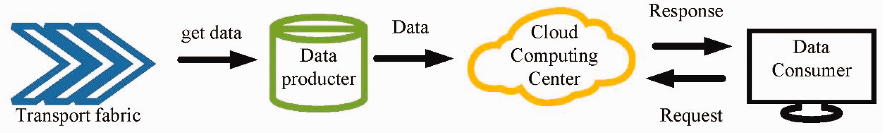
Cloud computing method.
Cloud computing uses a great deal of resources for computing and storing data and it can process data efficiently. However, there are some disadvantages to cloud computing. During detection, if the broadband network is insufficient, data transfer will become very slow. In addition, a large amount of data to be transferred can cause a heavy load and delays in transmission. Finally, if a defect is detected, delays in information transmission on the internet can cause the sorting equipment to miss the defective fabric, resulting in incorrect sorting.
Edge computing has been adopted for fabric defect detection based on the above-mentioned disadvantages of cloud computing. Edge computing is an open platform that integrates computing, storage and other functions on a single device, facilitating proximity to the data source. The entire edge computing deployment is shown in Figure 2. If there is a defect in the fabric, the edge device can detect it in the first instance and send the information to the cloud for storage. Compared to detecting on a cloud platform, edge detection can effectively avoid latency and improve detection efficiency.
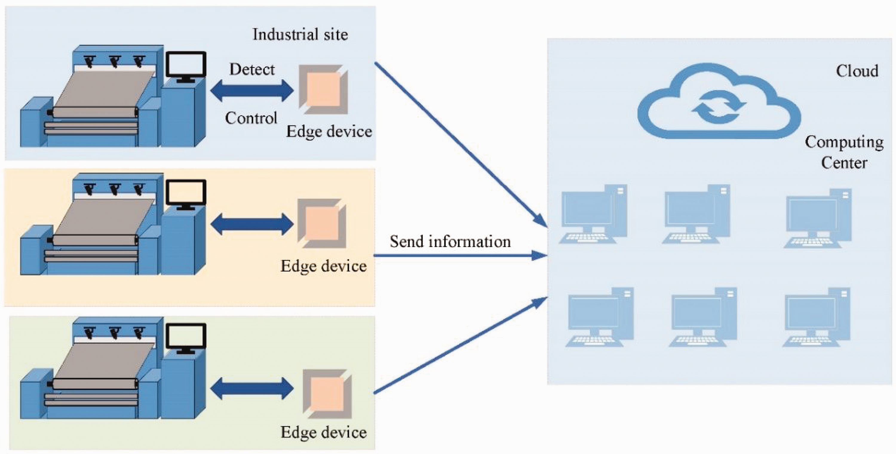
Edge detection graph.
The low power consumption of edge devices means that lightweight networks are often used for real-time detection. However, most current networks neglect detection speed for better accurate detection accuracy. In industrial production, detection efficiency will be compromised if speed is not met. As a result, many lightweight-based networks are being developed. A deep learning method for fabric defect detection on edge devices is proposed to meet industrial needs. In summary, the main contributions of this work are as follows.
The weight file generated by this neural network model is only 7 MB in size, which not only provides high accuracy but also ensures fast detection speed. The attention module and depth-separable convolution are used to reduce network parameters and improve the accuracy of network detection. In addition, the k-medoids clustering algorithm is used to optimize the pre-defined anchor points to improve the detection of the network. Finally, multiple small residuals are used instead of large residual modules and some of the bloated structure is removed, while the location of the backbone output feature measures is changed to increase the variability of the detection network. Edge devices are typically deployed in the industry. We use four different types of datasets to test the accuracy and speed of the network in JETSON TX2. Based on the above approach, we propose a detection system based on edge devices and verify the feasibility of the above approach.
The rest of the paper is organized as follows. In the second section, traditional defect detection methods, deep learning methods and the background of edge computing are described. In the third section, the network structure and the methods used are described. The fourth section describes the experimental metrics and hardware devices being used. The fifth section describes the experiments, mainly including a comparison of the algorithmic models presented in the third section, the device used in the experiment is edge device. In the sixth section, an industrial inspection site is mimicked to verify the feasibility of our method. In the final section, the work in this article is summarized.
In this section, we have summarized the necessity of fabric defect detection and the commonly used industrial inspection methods. By comparing them, we have found that deep learning-based defect detection methods can effectively improve detection efficiency and address detection challenges. Therefore, this paper proposes an object detection-based fabric defect detection method, and at the end of this section, we provide a summary of the contributions of this paper.
Related work
This section discusses three main aspects of fabric defect detection, namely traditional defect detection methods, deep learning methods and edge device detection.
Traditional methods
Traditional detection methods are divided into statistical, model-based and frequency-domain methods. Statistical-based methods were first used to detect fabric defects.
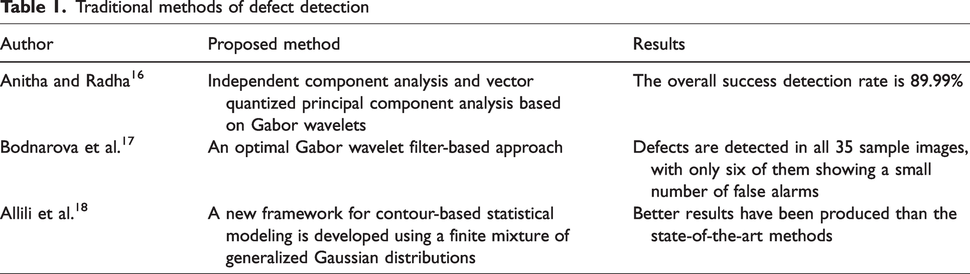
Statistical methods usually divide the image into image blocks. Textural features of standard textiles and features of defective areas are extracted by analyzing the distribution of grey values of fabric defective pixels. Commonly used methods include autocorrelation measures, co-occurrence matrices and variance averaging. However, the limitation of these methods is that it is difficult to distinguish between blurring of the average grey level and small defects on the fabric. Anitha and Radha 16 used independent component analysis algorithms to extract the desired texture and structural information from the image. The structural information can be reduced by phase coherence and then the template image can be distinguished from the input image. However, the method is only applicable to some defects and is not ideal for detecting defects in complex textures.
The texture of fabric exhibits periodicity, which can be detected through transformations between time and space domains, or between frequency domains. Common methods based on the frequency spectrum are the Fourier transform (FT), wavelet transform (WT) and Gabor filter. The FT is often used to extract texture information for detection by suppressing high and low frequencies in an image. Researchers have used the space-after FT to solve this problem, but it can be challenging to find a suitable function. On the other hand, WT and Gabor wavelets leverage the spatial frequency domain to detect defects; an optimized Gabor filter generation method was proposed by Bodnarova et al. 17 However, these methods may suffer from reduced efficiency due to their high redundancy and computational costs.
The model-based approach treats the texture characteristics of the fabric as a stochastic process. The main methods for defect detection using model statistical information are Gauss–Markov random field models and Gaussian mixture models. 18 These methods are effective in detecting fabric defects, but they are not as effective in detecting small defects. 19 This is because small defects are often confused with background noise and their small pixel area in the image is not easily detected accurately by statistical models. The above traditional methods for defect detection are summarized in Table 1.
Traditional methods of defect detection
Deep learning methods
The traditional detection method can be applied to most situations, but it is difficult to apply to situations with high computational complexity and small targets. Meanwhile, with improvements in computer hardware, deep learning-based methods have developed rapidly. Deep learning algorithms build a more complex network model. Their powerful model-fitting capabilities give them great research potential. CNN-based algorithms are widely used in the field of detection. Excellent networks such as Alexnet, 20 Vgg, 21 GoogleNet 22 and ResNet 23 have been proposed. Jeyaraj et al. 24 used a CNN to detect defects in six different fabric materials with an average accuracy of 96.55%, which demonstrates the effectiveness of the algorithm. However, the authors did not test complex textures. Liu et al. 25 proposed an algorithm applied to the Faster-RCNN algorithm for fabric defect detection, but the detection speed did not meet industrial requirements. Miao et al. 26 proposed a two-stage model approach combining the traditional WT and deep learning. It has higher accuracy and is more suitable for industrial production than the traditional and single-stage methods. However, its cumbersome detection speed of the two-stage detection step needs to be improved. Katiyar et al. 27 used a lightweight network based on MobileNetV2 for defect detection, but the detection of small targets is low. Jing et al. 28 proposed an efficient CNN for fabric defect detection, where the lightweight MobileNetV2 is used as an encoder and the softmax layer is used to generate a segmentation mask. Experimental results show that the proposed method achieves state-of-the-art performance in terms of segmentation accuracy and detection speed. Wang et al. 29 proposed the attention-based EfficientNet algorithm to detect cancer cells. The method obtained good results. Qi et al. 30 used the improved YOLOV3-Tiny algorithm to test railway firmware and achieved good results. However, with the advent of YOLOV4-Tiny, the algorithm needs to be updated. In 2020, Bochkovskiy et al. 31 proposed the YOLOV4 algorithm. They updated the new backbone structure, CSPDarknet53, and added new modules to the original network. Dlamini et al. 32 used the YOLOV4 algorithm to develop a real-time machine vision system that is relatively fast and detects defects in functional textiles. Lim et al. 33 proposed a lightweight model based on YOLOv4-Tiny. The authors improved the detection accuracy of the network model by modifying the loss function. Zheng et al. 34 proposed an improved YOLOv5-based method for fabric defect detection, which is based on the squeeze and excite (SE) module to improve network performance. Experimental results show that the proposed model, SE-YOLOV5, improves accuracy and generalization capability. Zheng et al. 35 proposed an improved YOLOV7 defect detection algorithm. By changing the clustering method, the attention mechanism and loss function were added to improve the network detection accuracy. Experimental results showed that the proposed YOLOV7 model can effectively achieve accurate detection of small objects in complex backgrounds. Haleem et al. 36 created a fabric defect detection system using a deep learning algorithm to validate the new method’s feasibility and its potential for application in the textile industry. Most importantly, the deep learning algorithm has high industrial promise, but it has a high demand for computing resources. When hardware resources are insufficient, the detection efficiency is severely reduced. The above deep learning references are summarized in Table 2.
Deep learning methods of defect detection

Edge computing
Edge computing is a low-cost, easy-to-deploy approach to computing that is different from cloud computing. It is deployed in a distributed manner, close to the data source for easy transmission, and addresses the disadvantages of transmission costs and internet latency. As a result, various edge device and deep learning-based solutions have been proposed over the past few years. NVIDIA is one of the graphics processing unit (GPU) manufacturers and some researchers have started to use NVIDIA JETSON TX2 to provide solutions for various tasks. For example, Blanco-Filgueira et al. 37 proposed a real-time embedded system to address multi-target tracking and edge computing applications. It demonstrates the feasibility of embedded devices in terms of frame rate and power consumption. Goyal et al. 38 used deep learning algorithms to detect and localize foot ulcers in diabetic patients. They used the edge device TX2 for deployment. Hoang et al. (2019) proposed an implementation of enhanced TX2 for enhanced signpost detection, which not only facilitates deployment but also enables fast detection. Song et al. 39 ported the EfficientDet network to TX2 and used a lightweight network to achieve real-time defect detection. Haut et al. 40 used the low-power TX2 to classify hyperspectral images with a deep learning algorithm. The deep learning algorithm classifies the hyperspectral images and achieves promising results. Therefore, TX2 will be used as a hardware platform to detect defects on fabric surfaces. The above edge computing references are summarized in Table 3.
Edge computing methods of defect detection
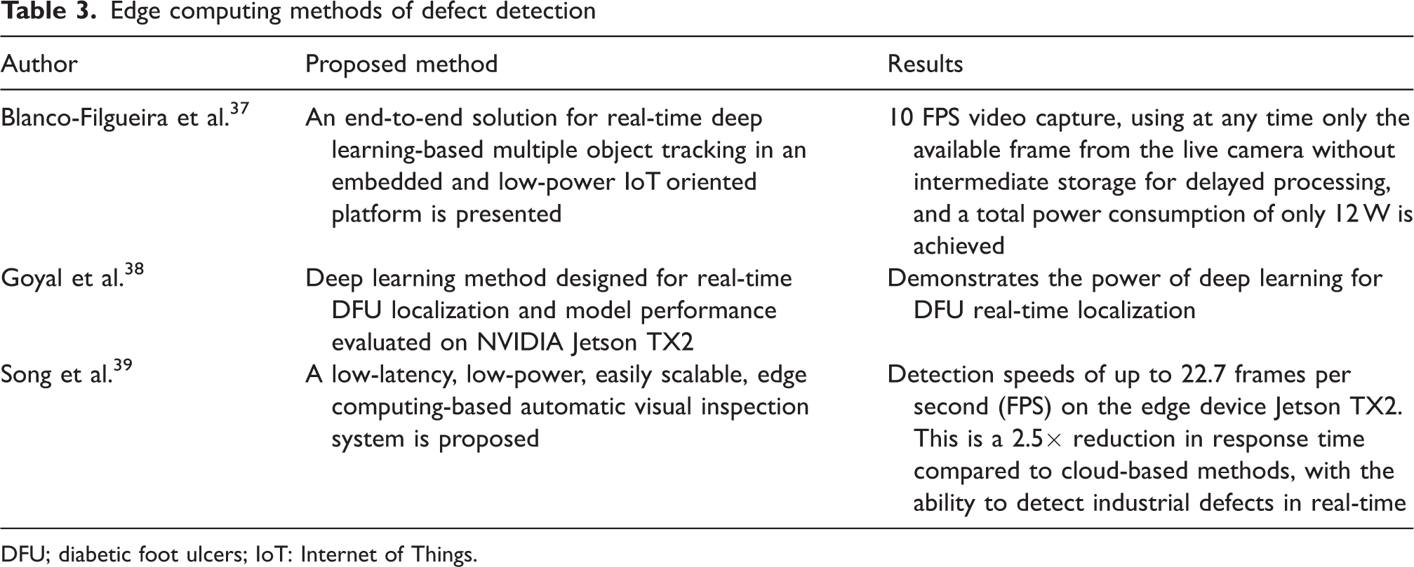
DFU; diabetic foot ulcers; IoT: Internet of Things.
In this section, we have classified the commonly used fabric defect detection methods, including traditional image processing methods, deep learning and edge computing. We have compared and analyzed these methods, evaluating their advantages and disadvantages. Ultimately, we have chosen the combination of deep learning and edge computing as the approach for fabric defect detection.
Proposed method
The lightweight network YOLOV4-Tiny 41 has been improved for industrial applications to make it more suitable for edge devices to meet higher requirements. The network structure has been improved by adding depth-separable convolution and attention modules to improve detection speed and accuracy. The clustering method is also improved to improve the accuracy of anchors for datasets with large differences.
Network structure
The overall network structure is shown in Figure 3. The original map is convolved by two 3 × 3s, batch normalization (BN) and downsampling used by the activation function to obtain 104 × 104 × 64 features. In the shallow layer of the backbone network, the position information of the defective target is mainly contained. Therefore, the spatial attention module is used in the shallow layer of the network to enable the network to learn more location information. After two large residual blocks, a feature size of 26 × 26 is obtained, at which point the network has many redundant feature layers, and the channel attention module is used to weigh the channels containing more semantic information about the defects, enabling the network to acquire more relevant semantic information.
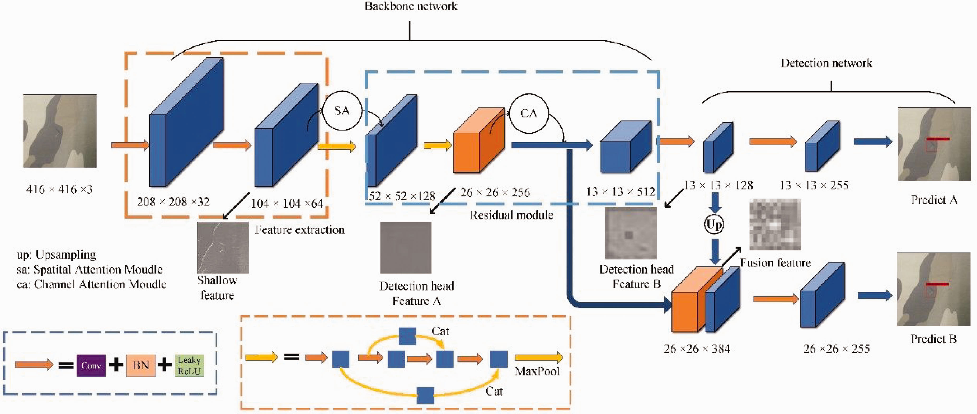
Network structure diagram. The input image undergoes multiple downsampling operations to obtain two different-sized feature layers for prediction. BN: batch normalization; ReLU: rectified linear unit.
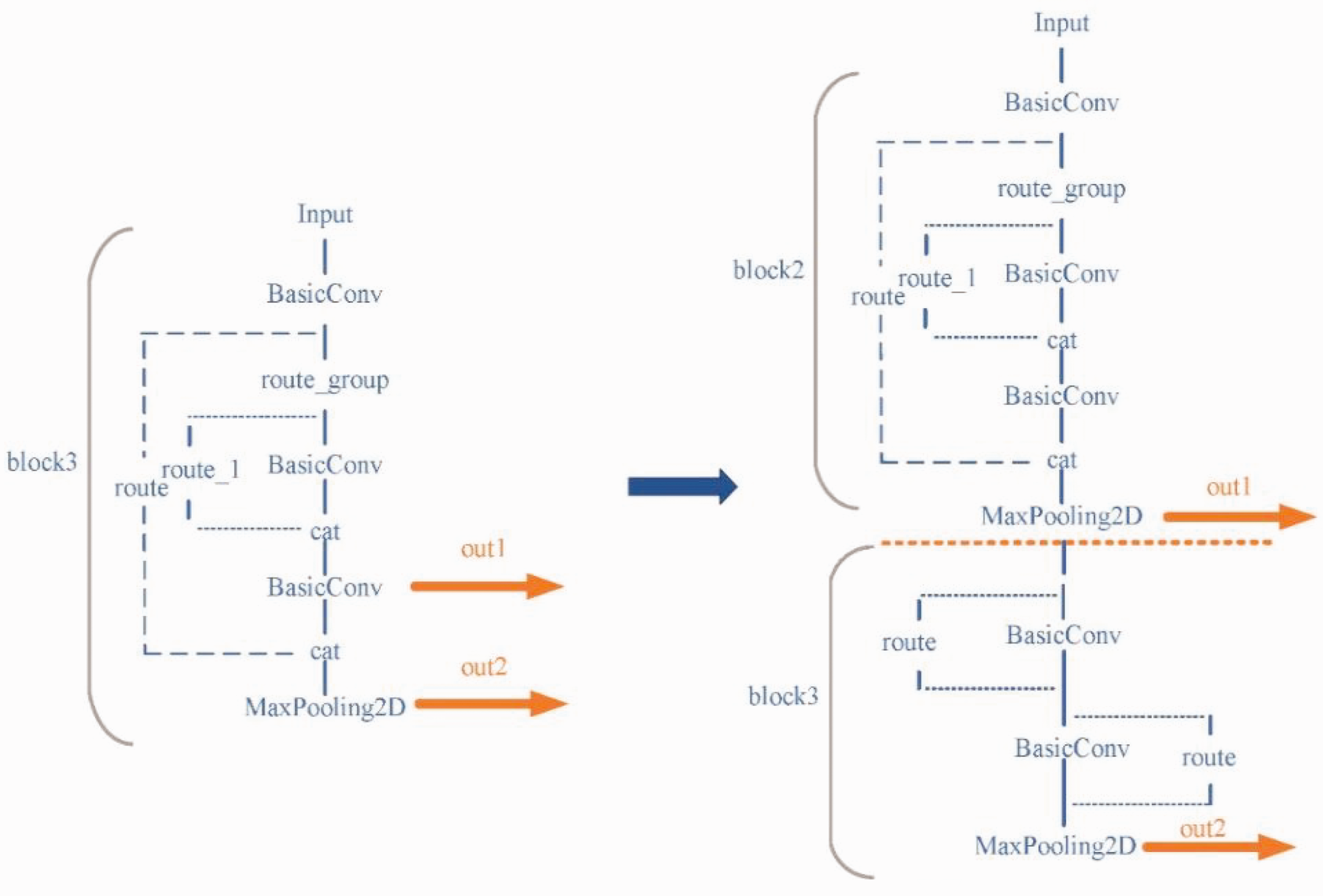
For the third large residual block, the original large residual structure has been modified, and two consecutive small residuals are used instead. At the same time, we changed the feature layer of the backbone output to the detection head to enrich the information in the different feature layers; the overall structure is shown in Figure 4. As the network goes deeper and the number of channels increases, each convolution requires large calculations, and we used this method to effectively reduce the network parameters.
Third residual block modification structure diagram.
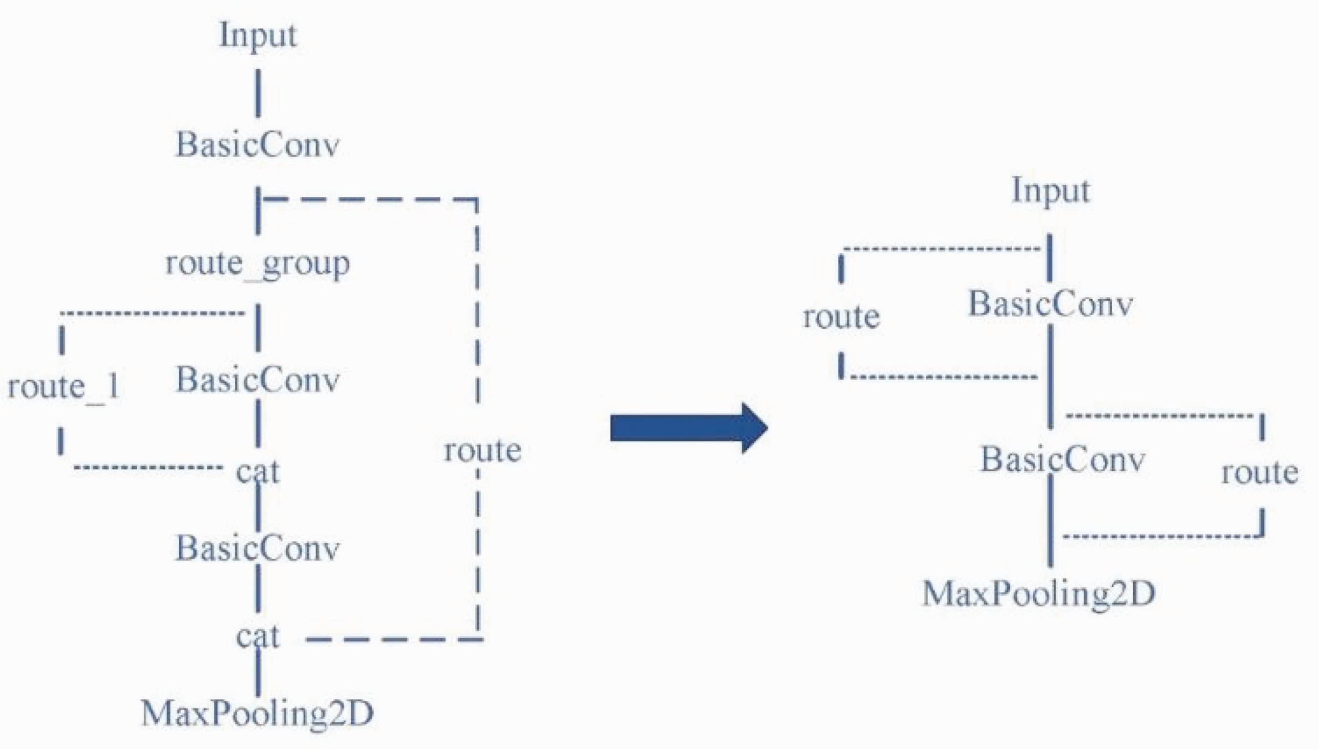
At the same time, the original network used the last two layers of the final residual block as the output feature measurement; the overall structure is shown in Figure 5.
Map of the change in the location of the output feature layer of the backbone network (original on the left, improved on the right).
After testing we find that this method is not effective for the detection of small targets, because the output to the 26 × 26 feature layer and the 13 × 13 feature layer output features are very close together, resulting in very similar feature information obtained, reducing the features obtained by the detection head. In addition, the 26 × 26 feature layer contains very much semantic information in the deeper layers of the network, while the 13 × 13 feature layer is mainly responsible for detecting small targets and the network needs to obtain more edge information to detect small targets. The output layer of the second large residual block is used as the input layer of the 26 × 26 detection head to improve its sensitivity to location information and the underlying feature layer as the 13 × 13 feature layer, which avoids the overlap of feature information in neighboring feature layers.
Anchor clustering method
This detection method requires pre-setting candidate anchors and then adjusting them based on the prediction frame based on the anchors. As a result, the clustering effect of the candidate anchors affects the detection results. For datasets with large differences, extreme data can bias the anchor points if the mean method is used, so to prevent the effect of extreme data, a new clustering method, k-medoids, is proposed to make it more applicable to datasets with large differences.
The k-medoids method is a clustering algorithm that aims to divide a set of data points into k different clusters, such that the similarity between data points within each cluster is as high as possible, while the similarity between different clusters is as low as possible. The steps of the k-medoids algorithm are as follows.
Select k random points (data points from the dataset). These points are also known as “medoids.” Assign all data points from the dataset to the nearest medoid using any distance formula, such as Euclidean distance or Manhattan distance. Now, choose new medoids by computing the median of all data points in each cluster. Continue with steps 2 and 3 until no data points change their cluster assignment between two iterations.
In summary, k-medoids is an effective clustering algorithm that can handle noisy and outlier data effectively, and is easy to implement and understand.
If the k-medoids algorithm is used, as in the initialization process, an intersection over union (IOU) with k cluster centers will be calculated for each sample. Equation (1) is used to find the cluster core closest to each point. The IOU is calculated as follows (Equation (2)):


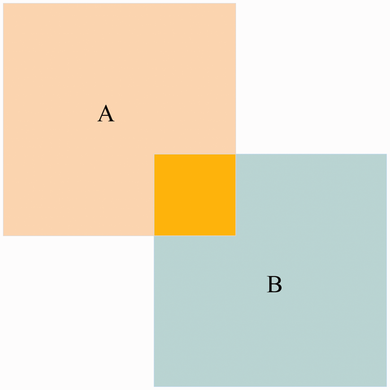
Intersection over union schematic.
Depthwise separable convolution
By using k-medoids clustering, the network can obtain better matching anchor points. To minimize the number of parameters in the computation, depth-separable convolution is used instead of normal convolution with a convolution channel count greater than 256, which effectively reduces the number of parameters in the network, as shown in Figure 7. A 12 × 12 pixel, three-channel feature layer (shaped as 12 × 12 × 3) is subjected to a deep convolution operation, and a three-channel image is processed into three feature maps. Then each convolution kernel convolves get an 8 × 8 × 1 feature map. This calculation performs independent convolutions for each channel, but it does not benefit the feature information for the same location information on different channels. Therefore, a 1 × 1 × 3 pointwise convolution method convolution kernel is used to combine the information from the different channels.
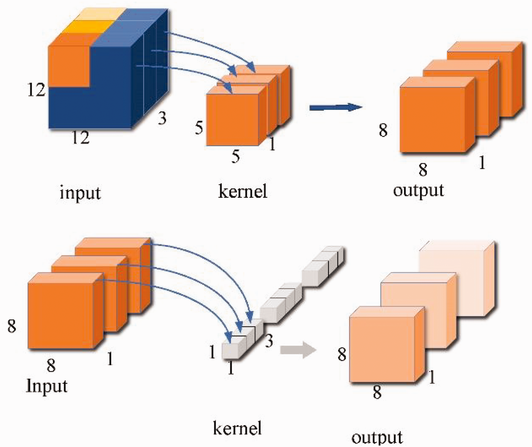
Depthwise separable convolution. Firstly, a 5 × 5 convolution is applied to the 12 × 12 × 3 feature map. Then, a 1 × 1 × 3 convolution is performed on the feature map, resulting in an 8 × 8 × 1 feature layer.
Attention module
To compensate for the lack of information extraction capability of the network, different attention modules are added to the network. For the location information available in the shallow network, the spatial attention module is used to extract the location information. As shown in Figure 8, the input features are connected by two description channels of maximum pooling and average pooling, and the weight parameters are obtained by the convolution and sigmoid.
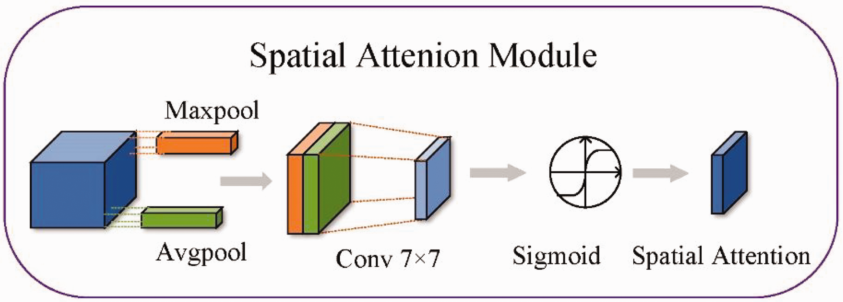
Spatial attention module. The input feature map undergoes pooling and convolution with a sigmoid activation function to generate a weight ratio for each pixel.
Deeper network information has higher semantic features and, as the network deepens, the number of feature channels increases after each convolution. Channel attention deepens the network to the channels containing key information. As shown in Figure 9, the input feature information is max-pooled and average-pooled to obtain two 1 × 1 × C feature information, which is sent to two convolutional layers. The first layer has C/r neurons. while the second layer has C neurons. These two layers of the network share parameters. With the two feature layers, the sigmoid obtains the distribution of weights for the different channels.
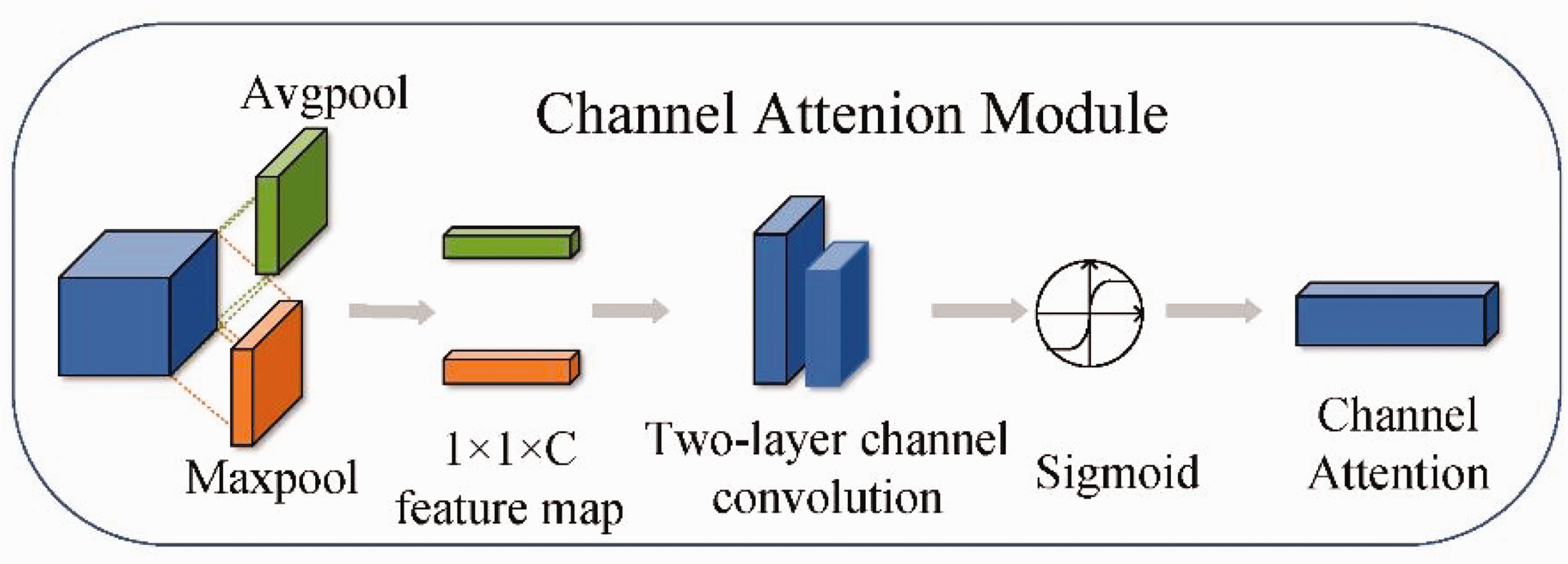
Channel attention. Channel attention generates a weight distribution for each channel. This weight distribution is used to amplify or attenuate each feature channel, selectively highlighting the most informative features and suppressing less important ones.
In this section, we have introduced the proposed method, which includes modifying the network architecture to make it more suitable for different sizes of fabric defects. The k-medoids clustering method is used to adapt to different defect sizes, and depthwise separable convolutions are added to improve detection speed. Finally, different attention mechanisms are applied at various locations in the network to enhance detection accuracy.
Experimental work
In this section, we performed tests according to the proposed methodology. The hardware is tested using an Inter Gold5118 CPU (2.30 GHz) processor with 128G RAM. NVIDIA GeForce 2080Ti is used for local experiments and the software is Windows 10 OS, PyTorch1 and Cuda10.1. The edge device NVIDIA JETSON TX2 is used for testing. The GPU uses the NVIDIA Pascal architecture and has 265 CUDA cores and 8 GB of RAM. The processor consists of a dual-core Denver2 processor and a CortexA57, which consumes only 7.5W, but is suitable for edge computing.
Experimental datasets
In the experiments, four different datasets are applied to the test network. The four datasets are camouflage fabric (CF), light blue striped fabric (LBF), dark red fabric (DRF) and grid fabric (GF), as shown in Figure 10. During training, the datasets are trained and tested in a 8:2 ratio. A test set is used to validate the effectiveness of the network training. The preprocessing step of resizing the image before feeding it into the neural network is a common practice in deep learning. Neural networks typically require images of a certain size as input, and if the original image size does not meet these requirements, it needs to be adjusted accordingly. One common method is to scale the image down to the desired size. Therefore, images of the original size of 256 × 256 are standardized to a uniform size of 416 × 416, as shown in Table 4.
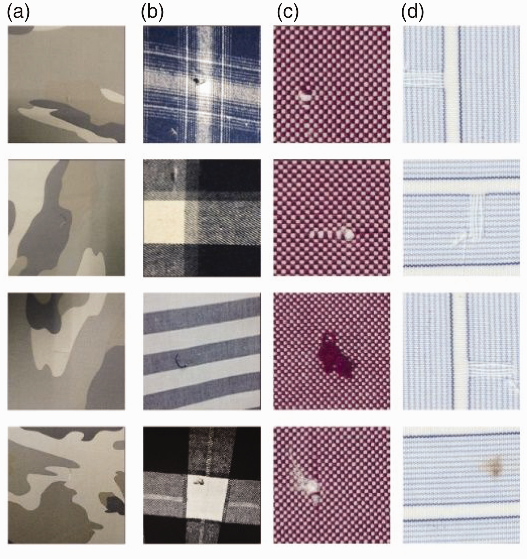
The four fabrics: (a) camouflage fabric; (b) light blue striped fabric; (c) dark red fabric and (d) grid fabric.
Dataset composition
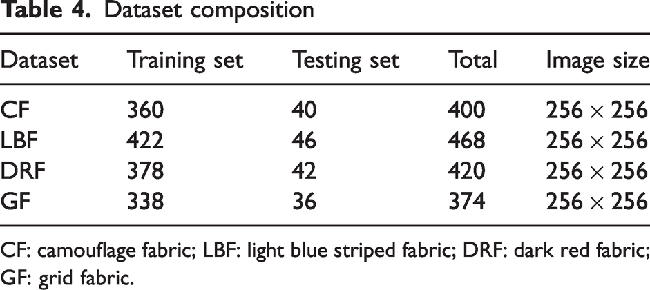
CF: camouflage fabric; LBF: light blue striped fabric; DRF: dark red fabric; GF: grid fabric.
Evaluation metrics
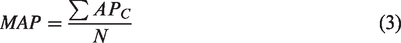
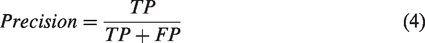
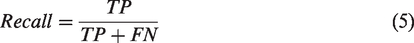
The experimental metrics consist of two main parts, detection speed (FPS), and detection accuracy (MAP). Among them, MAP is evaluated by the following indicators:

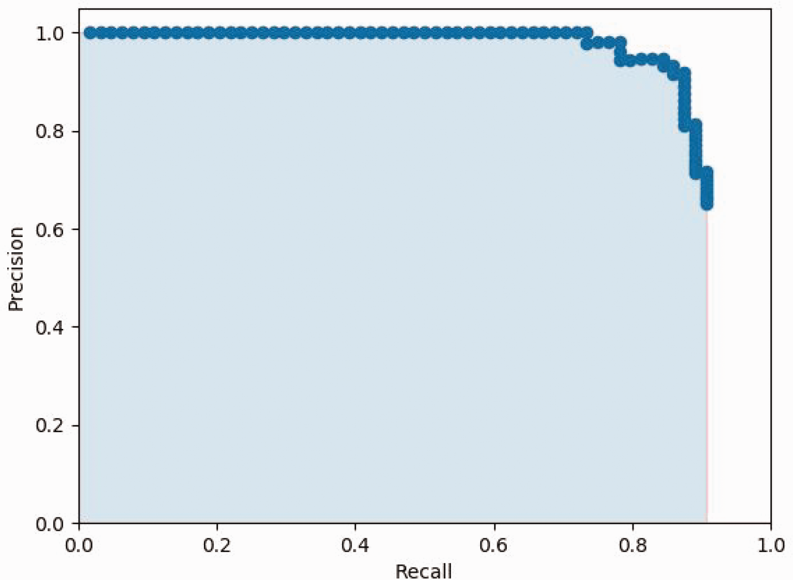
AP and recall and precision relationship diagram.
The size of the weight file obtained from training the neural network model can be indirectly reflected by using #Params(MB), which indirectly represents the complexity of the current algorithm.
In this section, we have introduced the dataset used in our paper. The entire dataset is captured in industrial production settings using the same equipment. We have also provided an overview of the relevant evaluation metrics.
Results and discussion
Ablation experiments
Anchor cluster analysis
The YOLO network needs to set the anchor in advance. The quality of the anchor indirectly affects the detection result, and the clustering effect of the anchor is crucial to result. There are large differences in the CF dataset, so the k-medoids and k-means methods are used for comparison. The results are shown in Table 5 and it can be found that k-medoids are on average 4% more accurate than k-means in terms of anchor points.
Clustering method impact
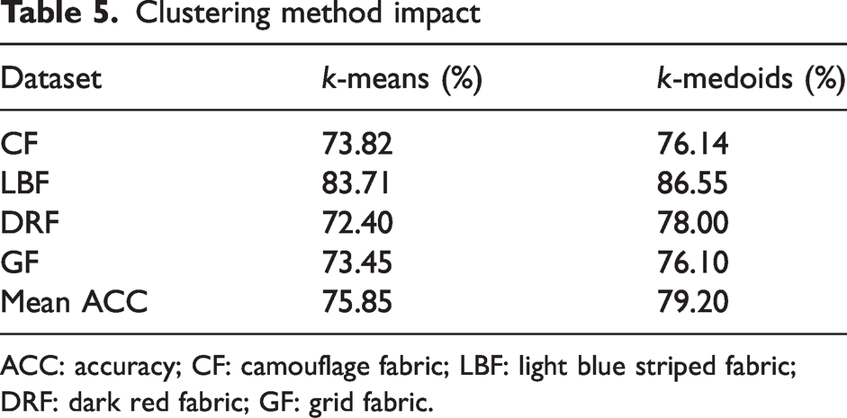
ACC: accuracy; CF: camouflage fabric; LBF: light blue striped fabric; DRF: dark red fabric; GF: grid fabric.
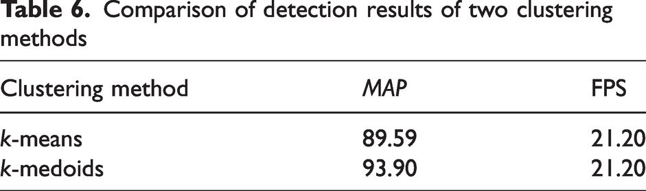
The anchor points obtained from the CF dataset are trained on the above two clustering methods and it is eventually found that the detection of the network after k-medoids clustering is higher than that of k-medoids on the CF dataset. Because of the large data variation in the dataset, when the k-means algorithm is used to adjust the anchor point parameters, the set size coordinates of the anchor points will receive more influence from the extreme points, which will reduce the effectiveness of defect detection. This problem can be avoided by the k-medoids algorithm. Therefore, our proposed clustering algorithm solves the problem of large data differences and improves the applicability of the algorithm. As shown in Table 6, the detection accuracy of the network has been greatly improved, with the average MAP increasing from 89.59 to 93.9. Our experiments have found that using our clustering algorithm provides better clustering results for datasets with greater differences.
Comparison of detection results of two clustering methods
Backbone comparison experiments
Among the lightweight models, the MobileNet and EfficientNet series are representative. To explore which backbone network is more suitable for the YOLO probe head, different backbone networks were used to verify the effect of different backbones on the detection results. Since MobileNetV2 41 and EfficientDet-D0 42 are the most representative, they are used to replace the original backbone network for experiments, respectively using Mobile-YOLO and Efficiency-YOLO. The 14th and 18th feature layers of MobileV2 are extracted as input to the YOLO detection head. The last feature layer and the fifth residual block of EfficientDet-D0 are extracted as input feature layers to the YOLO detection head. The results of the four datasets for the different backbone networks are shown in Figure 12.
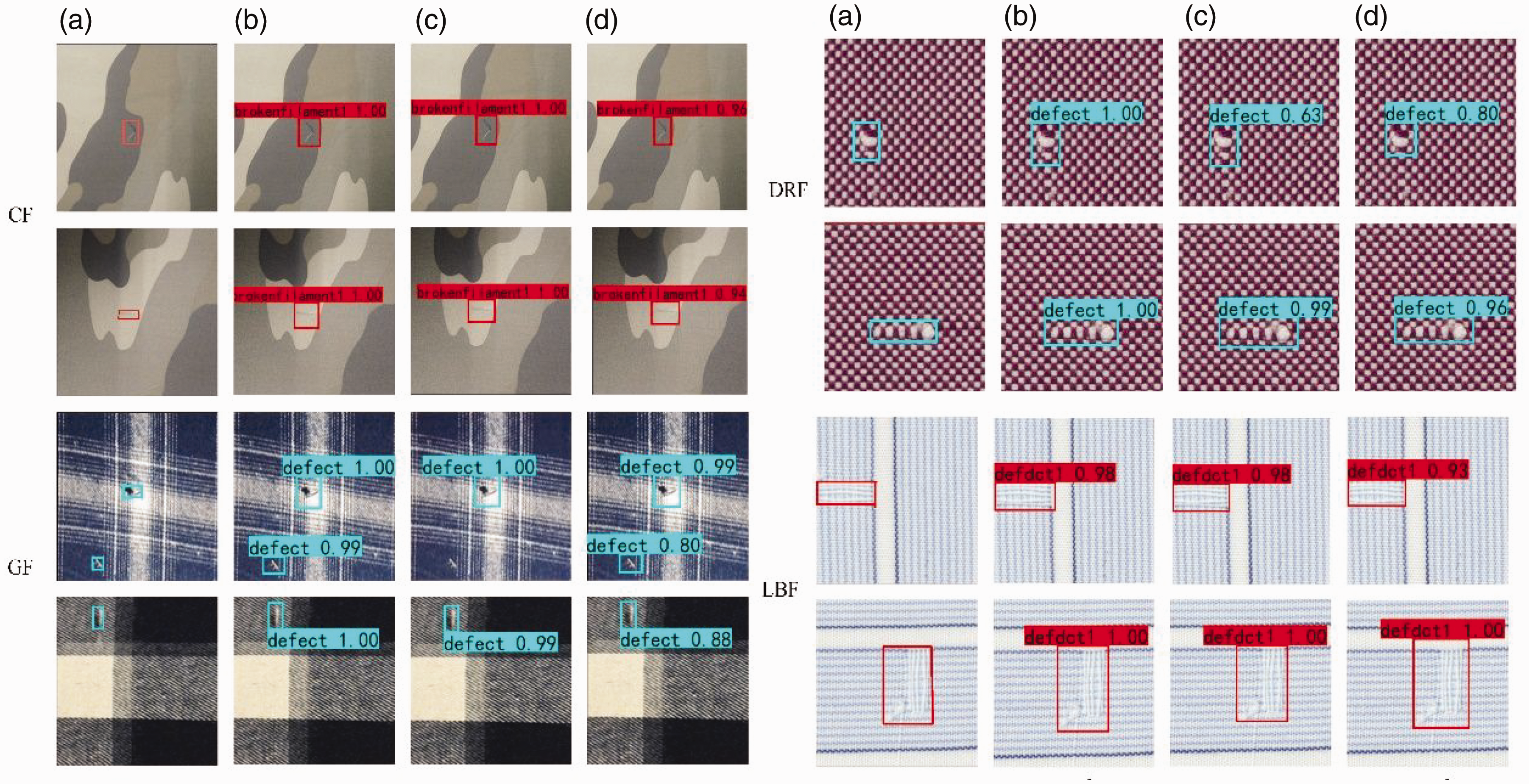
The detection results of the four datasets: (a) ground truth; (b) YOLOV4-Tiny; (c) Mobile-YOLO and (d) Efficiency-YOLO. CF: camouflage fabric; LBF: light blue striped fabric; DRF: dark red fabric; GF: grid fabric.
It is found that Mobile-YOLO does not detect small scratches in the first image of GF. Mobile-YOLO’s detection of small targets is not ideal. This is because this backbone is a linear network. The collection of information is not very effective and therefore this network is abandoned. Both the original network and Effective-YOLO are effective in detecting defects with good detection results. Although both Effective-YOLO and YOLOV4-Tiny can detect all defects, the backbone network of Effective-YOLO is very complex, resulting in a slow detection speed.
By analyzing Table 7, it can be seen that the average accuracy of YOLOV4-Tiny is the highest among the three backbone networks. The detection speed reaches 21.20 FPS, which is much faster than the Effective-YOLO network. Therefore, YOLOV4-Tiny has high comprehensiveness in a lightweight backbone network. YOLOV4-Tiny is chosen for the next ablation experiment to determine the effectiveness of other modules.
The test results of the different backbones in the YOLO series
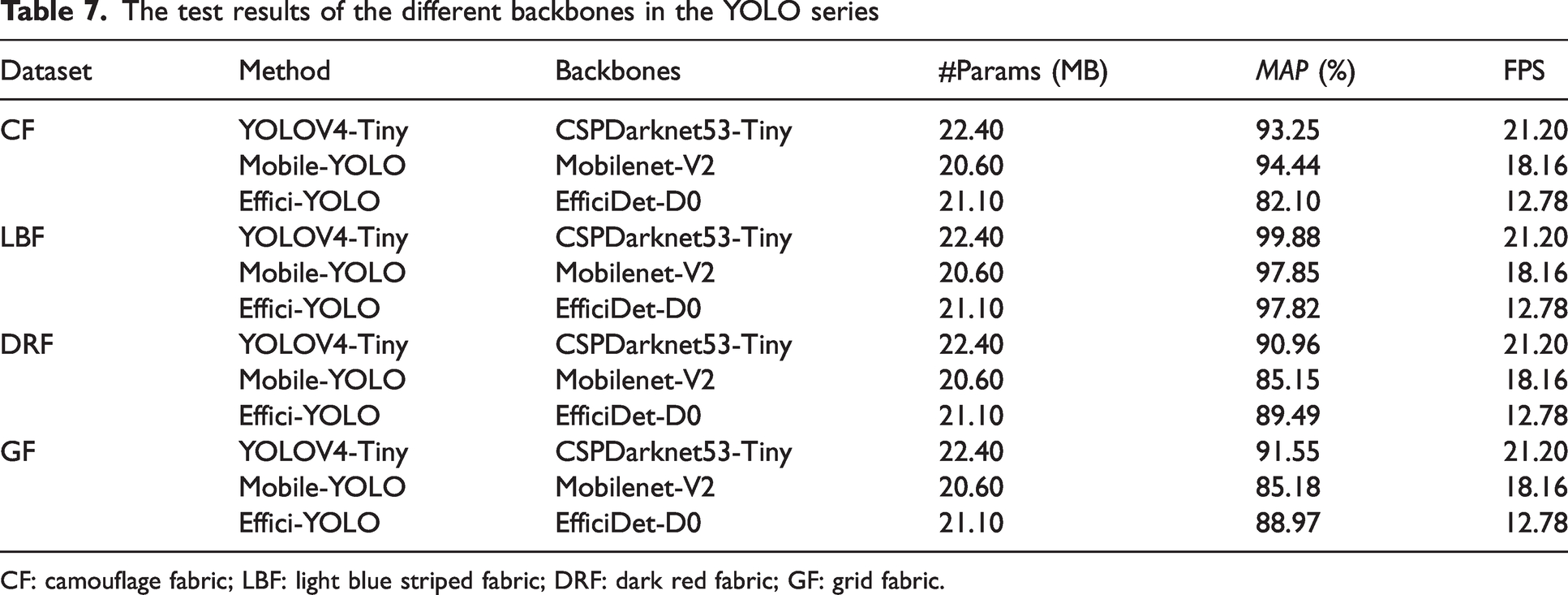
CF: camouflage fabric; LBF: light blue striped fabric; DRF: dark red fabric; GF: grid fabric.
Module innovation experiments
To determine the effectiveness of each module, as shown in Table 8, the following modules are gradually added to the network to test its effectiveness, and the best solution is ultimately obtained. The following modules are changed separately.
Ablation experiment of different modules
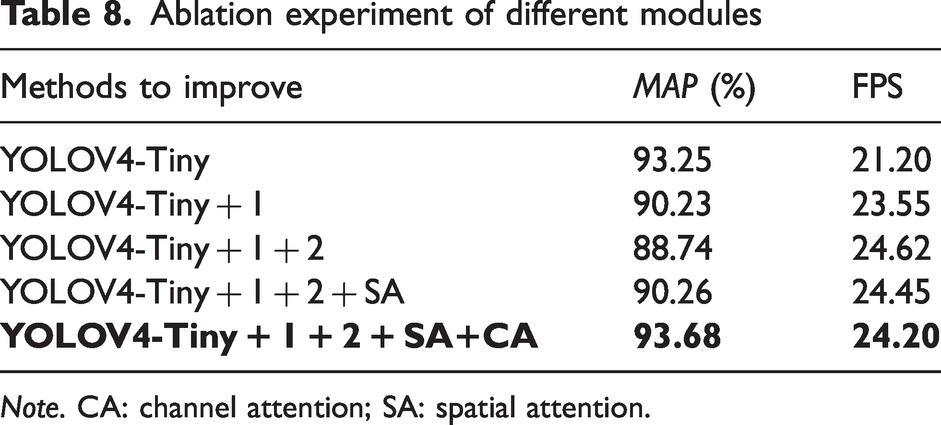
Note. CA: channel attention; SA: spatial attention.
The position of the backbone output feature layer is replaced and the last large residual structure is changed to multiple small residual edges. As shown in Figure 4, the last two feature layers of the original backbone are used as input to the detection network. The close proximity between the two feature layers in this approach results in a great deal of overlapping information and the location information in the shallow layer is lost, so the second residual block is used as the shallow feature layer input. Also deep in the network, as the number of channels increases, the amount of computation per convolution increases exponentially and, to reduce the computation time, the last residual block is replaced with two small residual edges to reduce the number of computational parameters.
When the number of convolution layers is greater than 256, the normal convolution is replaced by depth-separable convolution. Feature layers with a high number of channels require significant computation time for each convolution operation. This issue can be addressed by using depth-separable convolution, which effectively reduces the computational parameters involved. Consequently, convolutions with more than 256 layers are replaced by deeply separable convolutions.
The Spatial Attention module (SA module) has been added. Spatial attention can effectively increase the network’s ability to extract spatial.
The Channel Attention module (CA module) is used. As the network deepens, the number of channels increases exponentially after each convolution. To extract channels containing more defective information, channel attention uses a sigmoid function to assign weights so that the network applies more weight to channels containing more useful information and obtains more semantic information about the defects.
The CF dataset is used for testing the ablation experiment. After replacing the position of the backbone output feature layer and changing the residual structure to add a depth-separable depth, the network speed improved significantly, by about 14%. This is mainly due to a significant reduction in the number of computational parameters significantly reduced, which is more suitable for detection on edge devices. However, there is a decrease in accuracy. The addition of the attention module improves the network’s extraction of positional and semantic information, and the change in position of the feature layer of the output detection head increases the amount of information acquired by the network and improves the network’s detection accuracy.
Network comparison experiments
The feasibility of our proposed method is verified by comparing it with other networks. The networks compared include the original network, MobileNetV2, EfficientDet- D0, YOLOV4, Faster-RCNN, YOLOV5S and YOLOV7, and the metrics tested include accuracy MAP and speed FPS.
YOLOV5 and YOLOV4 are high-precision versions of the YOLO series object detection algorithms, which have greatly improved accuracy and speed compared to previous versions. In comparison, YOLOV5 uses more efficient network structures and data augmentation techniques, making it more advantageous in terms of both speed and accuracy than YOLOV4.
YOLOV7 is a new object detection algorithm that differs from previous YOLO series algorithms in that it adopts modular design and uses attention mechanisms to improve feature representation, which can result in more precise detection results.
MobileNetV2-SSD is an object detection algorithm designed for mobile devices, which uses the lightweight MobileNetV2 as the feature extractor and SSD algorithm for detection. It has the advantages of a lightweight model, fast speed and high accuracy, making it suitable for real-time detection applications on mobile devices.
Faster RCNN is a region proposal-based object detection algorithm that uses a RPN (region proposal network) to extract candidate boxes and region of interest (RoI) pooling for object classification and localization. Compared to YOLO series algorithms, Faster RCNN is more accurate but slower, making it suitable for scenes that require high accuracy.
YOLOV4-Tiny is a lightweight version of YOLOV4 that maintains high detection accuracy while having a smaller model size and faster detection speed, making it suitable for embedded devices and real-time detection applications.
YOLOV4-TinyS is a fabric defect detection method proposed by us for edge devices. It is based on YOLOV4-Tiny and has been improved by optimizing the network structure and changing the location of the network output layer and the size of the residual blocks extracted from the backbone. In addition, different attention structures have been added to improve the detection accuracy of the network. Finally, compared to the original network, there is a significantly higher improvement in speed.
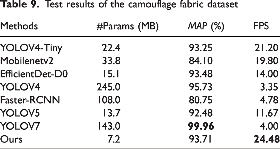
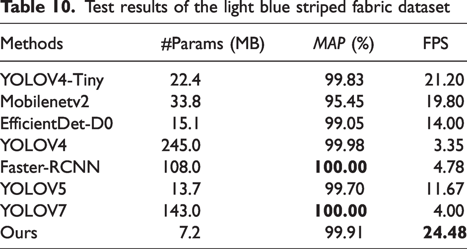
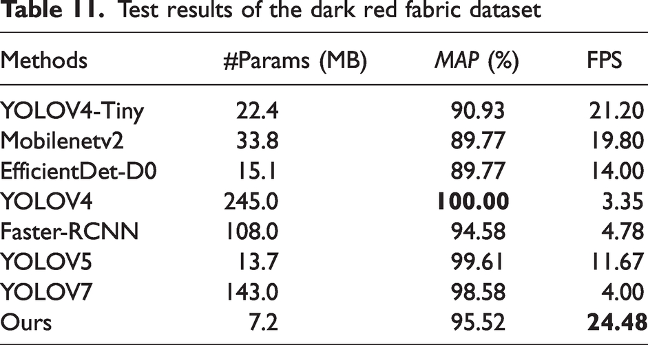
The above networks are tested on four datasets. The results are shown in Tables 9 –12.
Test results of the camouflage fabric dataset
Test results of the light blue striped fabric dataset
Test results of the dark red fabric dataset
Test results of the grid fabric dataset
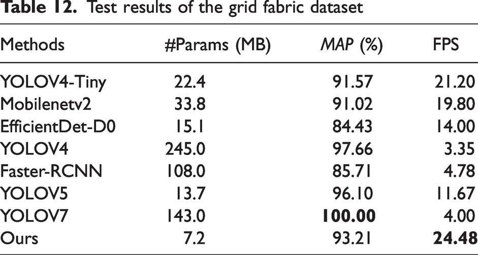
It can be found that our network performs well on these four datasets. The accuracy is slightly lower than that of YOLOV4, mainly because YOLOV4 has a large number of neurons which makes it have better detection, but the detection speed is only 3.35 FPS, which is not suitable for edge devices, while our method is much faster than YOLOV4.
Compared to the other networks, our network is much faster than the others. In addition, it also has a high degree of accuracy. Through analysis, we have added modules that reduce the network parameters to give a significant speed improvement without loss of accuracy, which is more suitable for edge devices and therefore gives our network an advantage in lightweight networks.
The defect detection results are shown in Figure 13. It can be found that defects in GF cannot be fully detected by MobilenetV2. This is mainly because this network structure is not sensitive to small targets. EfficientDet-D0 did not detect anything on the LBF dataset. This is because it does not learn the defect features well. Although YOLOV5 correctly detects defective regions on the four datasets, the confidence level of detection needs to be improved. The MAP distribution of Faster-RCNN on the four datasets is not uniform and the speed is not satisfactory. The detection speed of YOLOV7 is much lower than that of our algorithm and the detection confidence is very low for each dataset. Although YOLOV4 and our method can detect all defects, the speed of YOLOV4 is far from satisfactory. In addition, our detection frames are much closer to the real frames. Overall, our network has a great advantage in terms of speed and high detection accuracy.
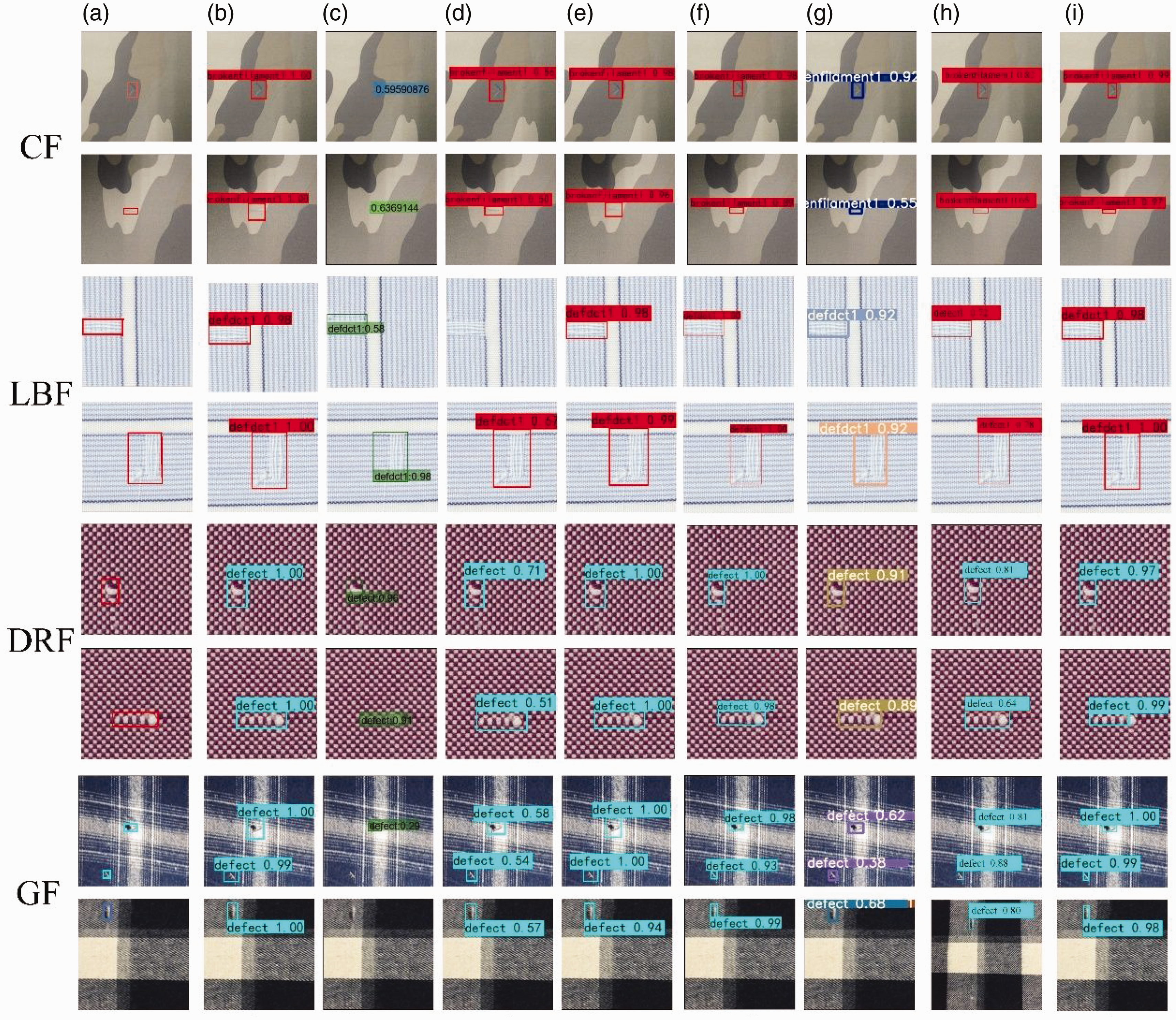
The detection results of the comparison experiment of the four datasets, from (a) ground truth, (b) YOLOV4-Tiny, (c) Mobilenetv2, (d) EfficientDet-D0, (e) YOLOV4, (f) Faster-RCNN, (g) YOLOV5, (h) YOLOV7 and (i) ours. CF: camouflage fabric; LBF: light blue striped fabric; DRF: dark red fabric; GF: grid fabric.
At the same time, our network has a strong synthesis capability for these four datasets. This is mainly because it is better able to extract key texture information and is more sensitive to small targets. The ability to balance accuracy and speed makes our network feasible.
The above detection network is shown in Figure 14. It can be seen that our method has the fastest speed and a high accuracy rate in the four datasets. In general, lightweight networks need to ensure that the inference speed of the network is maximized while maintaining accuracy and, at the same time, our method has better robustness with little bias on these four datasets. In summary, our method can achieve detection accuracy while maintaining speedup, which is in line with the industry’s requirements.
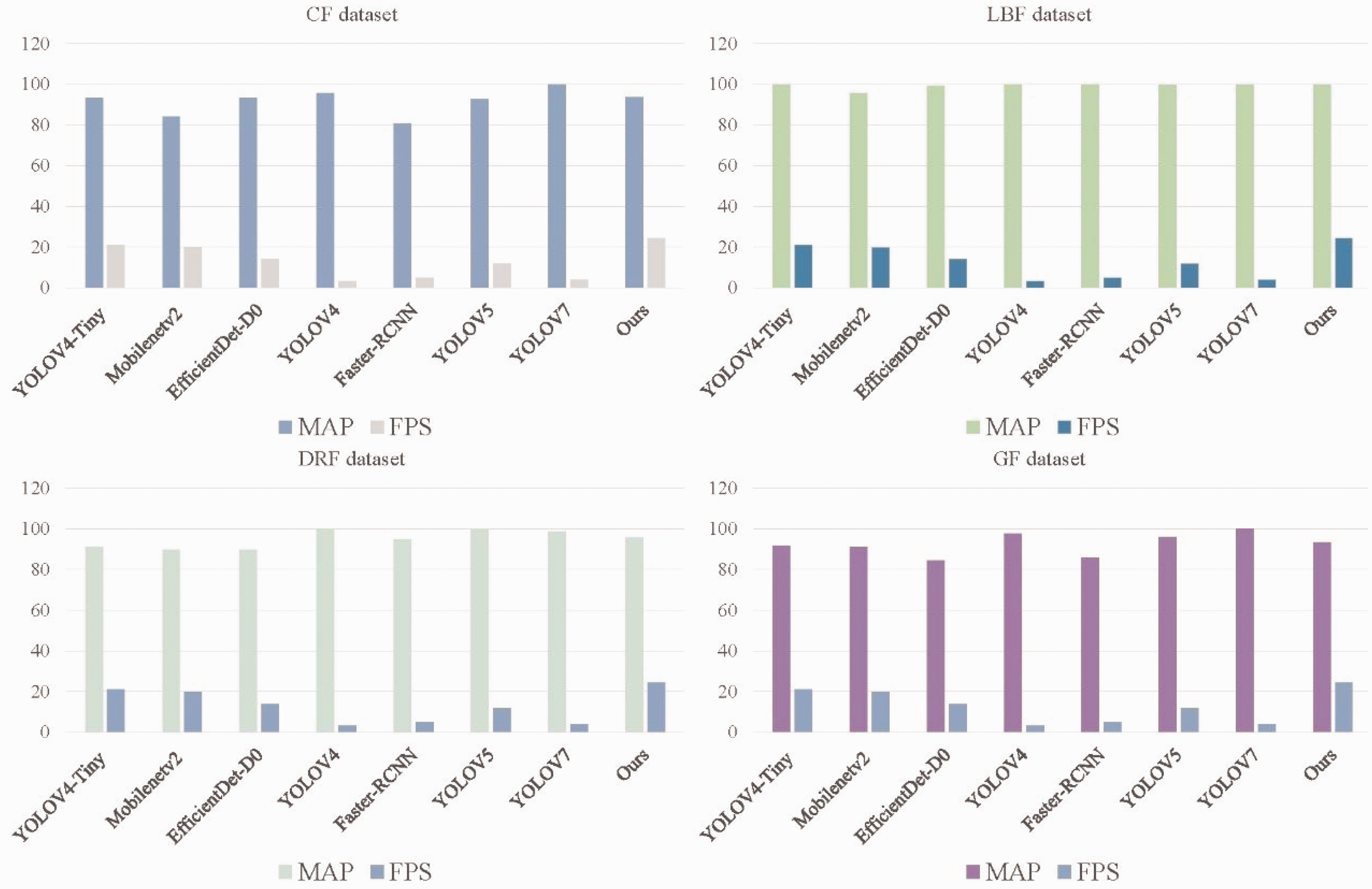
Performance comparison chart of different algorithms. CF: camouflage fabric; LBF: light blue striped fabric; DRF: dark red fabric; GF: grid fabric.
In order to verify that our network is not overfitting during training, the loss curve of the validation set during its training process is displayed. Through Figure 15, it is discovered that the network gradually stabilizes after 100 epochs. In the experiment, we choose the weight file where the loss has just stabilized.
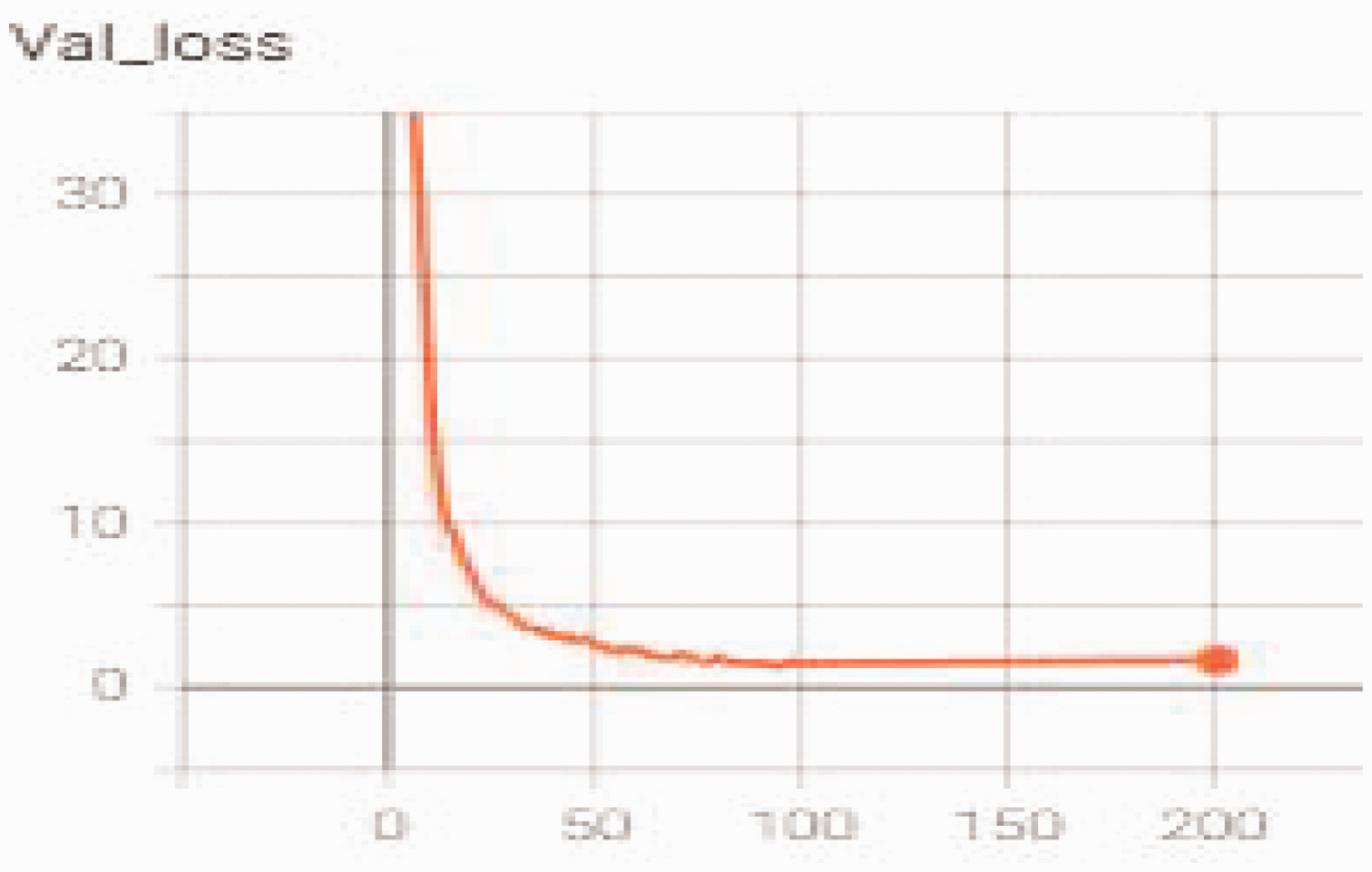
Convergence test of YOLOV4-TinyS on the dataset.
In this section, we conduct relevant experiments on the proposed method, including ablation experiments for each component and comparative experiments with related networks. Through experimental comparisons, we validate the effectiveness of our method. It achieves real-time detection on edge devices and exhibits a faster detection speed compared to other networks.
Application
A system that simulates industrial inspections has been built and new algorithms are used for testing. A batch of images is first sent to the cloud for training and, once training is completed, the weight file will be sent to the edge device and then the conveyor belt is opened for online detection. The flow chart in Figure 16 shows a network is trained for each dataset by our system. When different fabrics need to be detected, the weights need to be retrained, which takes about 2 hours.
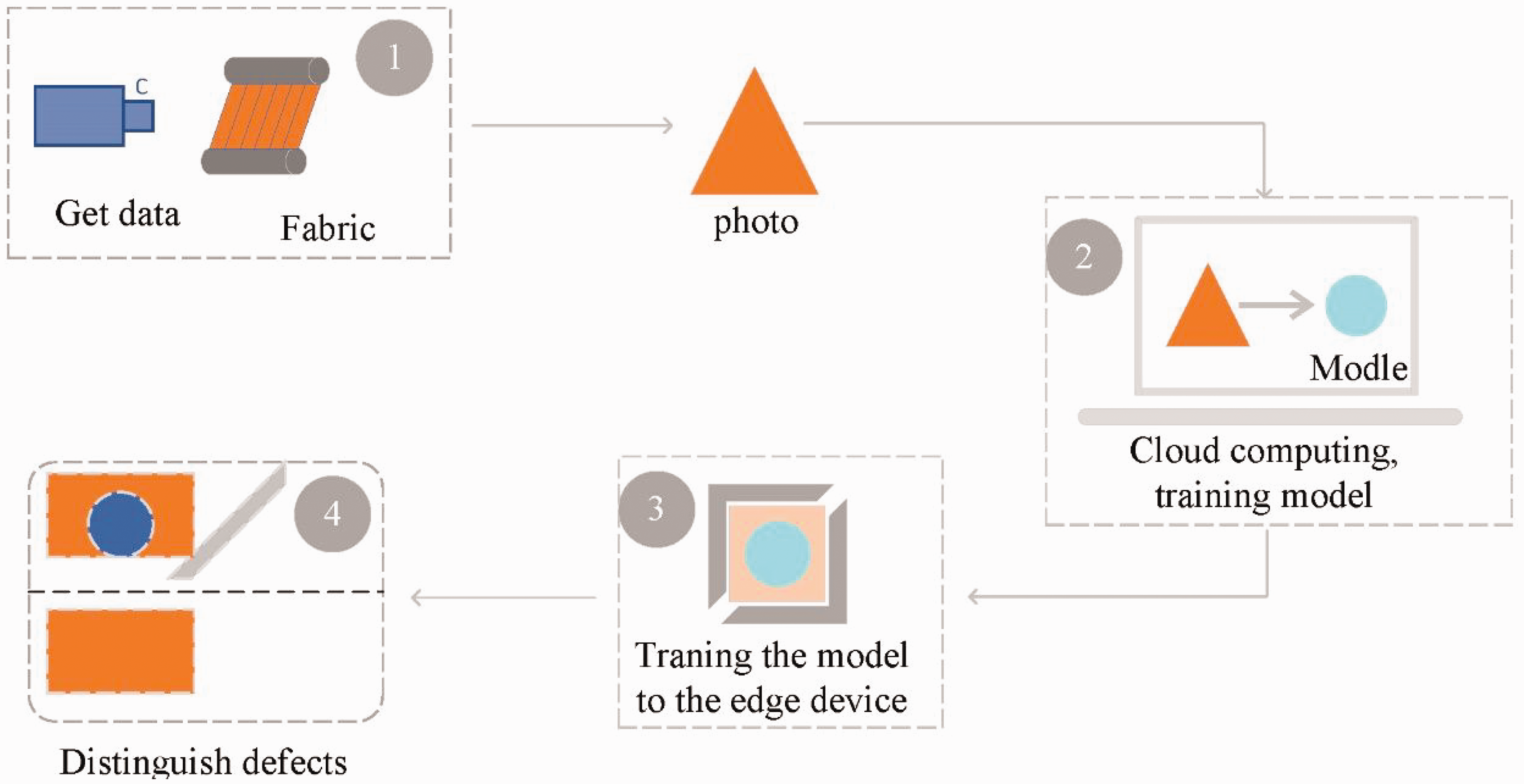
Detection flow chart. The data captured by the camera is sent to the cloud, and the network is trained in the cloud to obtain weights. The trained network model is sent to the edge device for real-time detection, and finally the defective fabrics are sorted.
Experimental tools
TX2 is used as a detection device, adopting a 2.1 m long conveyor belt, and the transmission speed is 11.4 m/min, which simulates the industrial site for fabric inspection. A light-emitting diode (LED) is used as a ring light source for lighting, the camera is a Basler-acA2500-10gmarea scan color industrial camera and the lens used to collect the pictures is a Basler C125-0618-5M 6 mm. A real shot of the detection is shown in Figure 17.
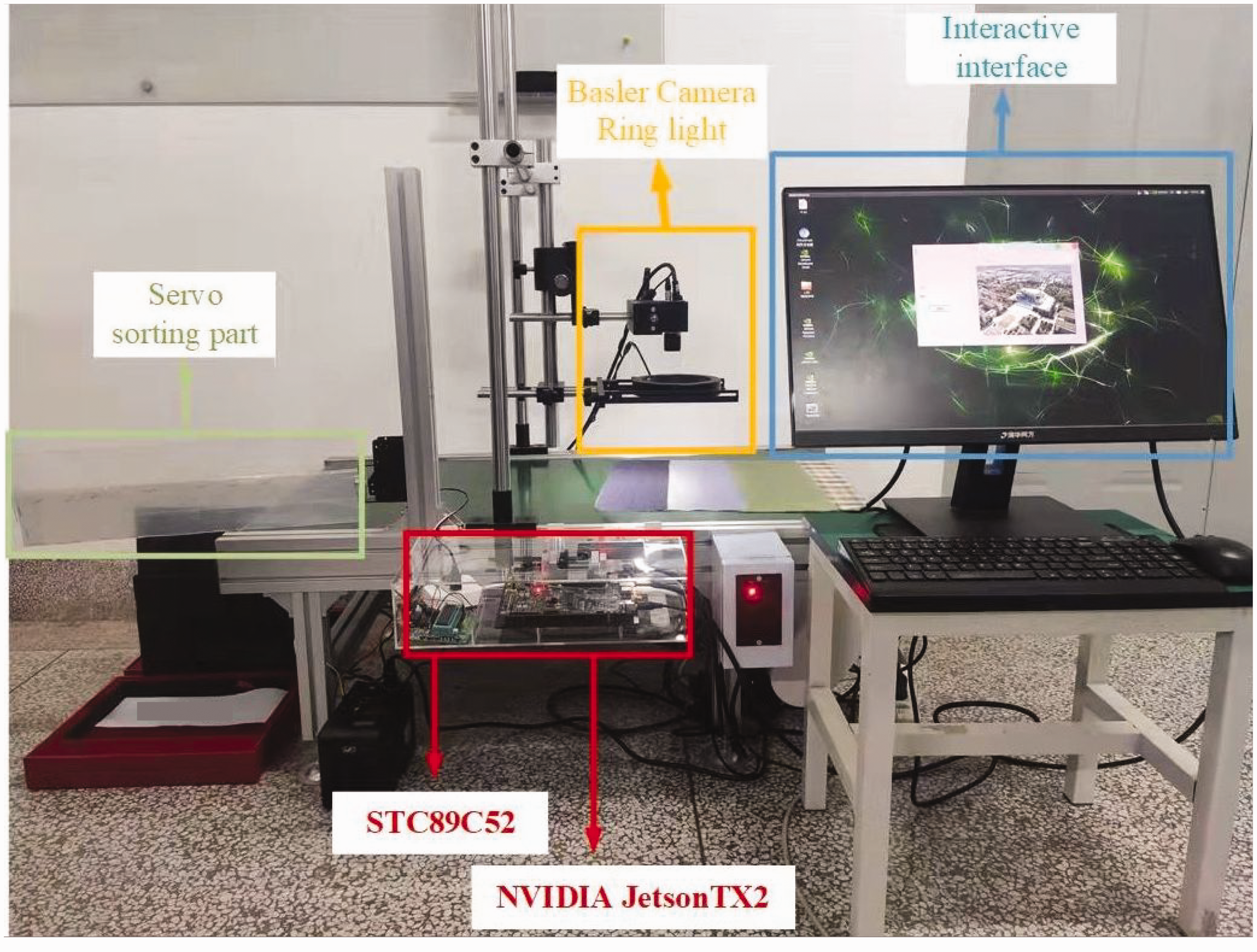
Fabric defect detection system. The whole system includes a light source, shooting part, detection part and display part.
Experimental method
Images of the defective fabric are collected by the Basler camera during transmission. After training the network, we embed the trained model into TX2 for detection. We have built a user interface that enables real-time detection of both video streams and pictures. In Figure 18, when a defect is detected, the defect category, defect confidence, prediction frame coordinates and the number of defects are recorded as a log. At the same time, TX2 will send a signal to the steering gear and use the baffle to distinguish the defects. After verification, our method can effectively detect common fabric defects.
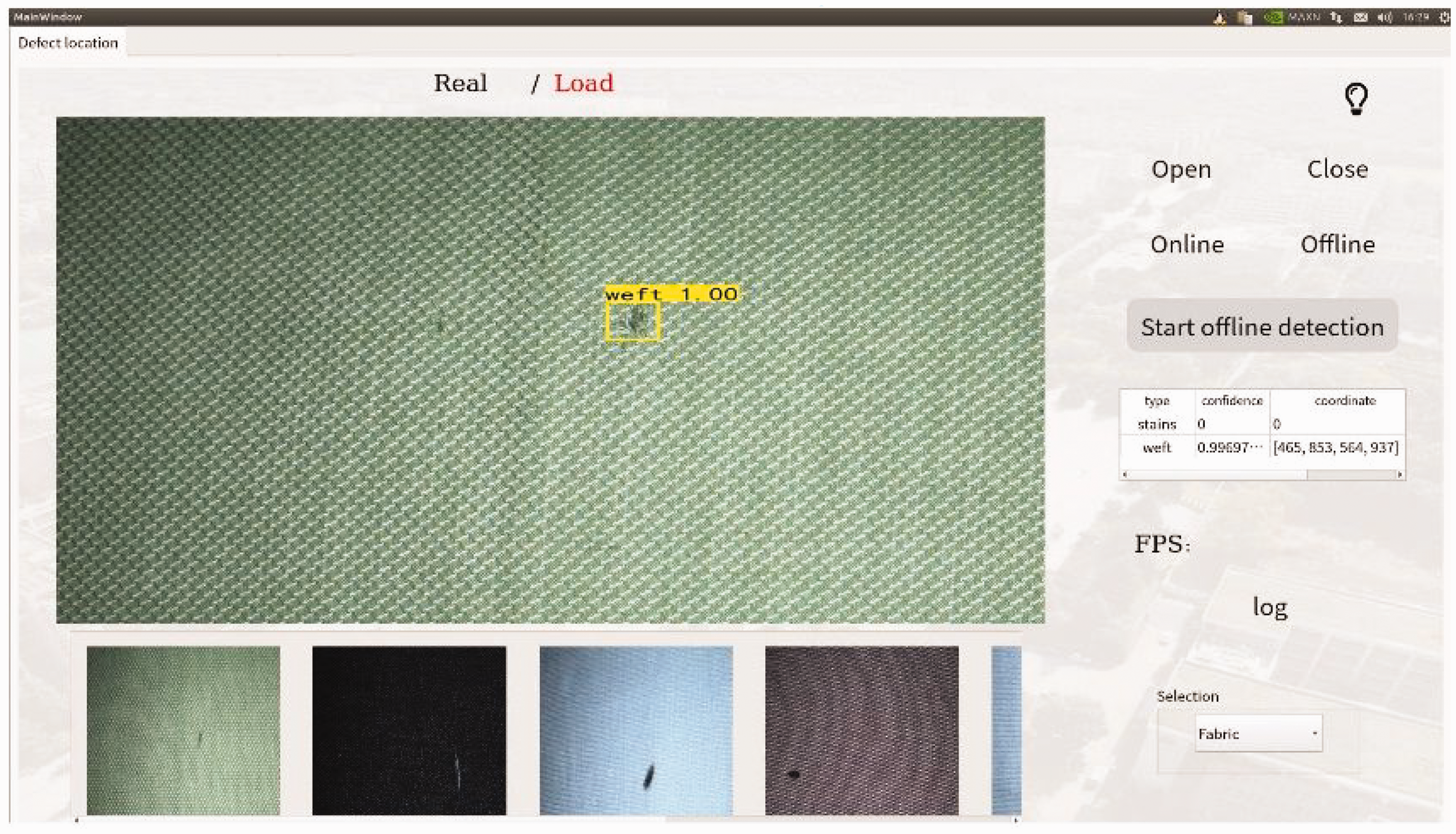
User interface.
In this section, we construct a defect detection system, which includes a conveyor belt, edge devices and a GUI human-machine interface. Ultimately, through testing, our method can effectively detect fabric defects on the conveyor belt. This provides a foundation for practical industrial fabric defect detection and validates the effectiveness of our approach.
Conclusions
In this article, YOLOV4-TinyS, a fabric defect detection method suitable for edge devices, is proposed. We change the position of the feature output layer in the backbone network to improve sensitivity to location information and increase the difference in output feature layers to enrich the information obtained by the network. The bottom residual module is changed and depthwise separable convolution is used instead of normal convolution to reduce the number of network parameters and, finally, the attention module is used to improve the network’s ability to obtain defect information. Experiments show that the proposed network can effectively improve the ability to detect fabric defects and that it has superiority over other advanced methods. The proposed method is verified for feasibility by simulating an industrial inspection site, and it meets the real-time detection requirements on an edge device, a Jetson TX2. In the future, we will attempt to develop more defect detection methods for industrial scenarios to improve actual detection efficiency.
Footnotes
Declaration of conflicting interests
The authors declared no potential conflicts of interest with respect to the research, authorship, and/or publication of this article.
Funding
The authors disclosed receipt of the following financial support for the research, authorship, and/or publication of this article: This work was supported in part by the Innovation Capability Support Program of Shaanxi (program no. 2021TD-29), in part by The Youth Innovation Team of Shaanxi Universities, in part by the National Natural Science Foundation of China (grant 62176204) and the Key Research and Development Program of Shaanxi (no. 2022GY-066).