
Abstract
The impact resistant composite has excellent energy absorption efficiency, but the structure and material selection of the composite have great influence on its energy absorption. In order to explore the effect of structure on the energy absorption of Ultra-high molecular weight polyethylene (UHMWPE) composites and the application potential of new aramid core-spun yarn and new polyester core-spun yarn in impact resistant composites. The UHMWPE composites with different fiber orientations and stacking sequences structure, as well as the new hybrid composites containing aramid core-spun yarn and polyester core-spun yarn were tested by low-velocity impact test and scanning electron microscope (SEM) observation. The differences of energy absorption of UHMWPE composites with different structures and the advantages of the new hybrid composites were analyzed. The results show that the energy absorption of the 45°/0°/90°/−45° UHMWPE composite is 15% and 86% higher than that of the 0°/90°/0°/90°UHMWPE composite and the 0°/90°/45°/−45° UHMWPE composite, respectively, which is the best structure among the three composites. The energy absorption performance of the composites introduced with aramid core-spun yarn and polyester core-spun yarn were improved by 223% and 202%, respectively, so that the energy absorption performance was significantly improved by new yarns.
Introduction
With properties such as light weight, high strength, high modulus and high temperature resistance, good impact resistance and electromagnetic properties, fiber composites are widely used in various fields such as aerospace, weapons, construction, and transportation.1–3 Composite laminates are made of single-layer fiber sheets laid in laminated layers and processed by bonding and thermal lamination. They have excellent performance in impact resistance. Therefore, many scholars at home and abroad have studied them one after another.4–6 Cai and Zhou 7 studied low velocity impact composite laminates. The relationship between the low velocity impact velocity and the residual compressive strength of composite laminates was studied under the impact of the drop hammer, taking the low velocity motion of the drop hammer in the laboratory as the initial velocity. However, the structure of the composite material is a key factor in determining its impact resistance. Composites exhibit different mechanical properties when the lay-up thickness, angle and order of the composite vary.8–11 Jia et al. 12 studied the residual velocity of bullets on composites with different lay-up angles after impact and the damage characteristics of composites with different lay-up angles after impact, and found that composites with [45/−45°] lay-up angles had better energy absorption relative to composites with [0/90°] lay-up angles when the bullets penetrated the laminate at a velocity of 600–900 m/s. Similarly, Ceng et al. 13 conducted low-velocity impact tests on [0/45/−45/90]8 unidirectional laminates, [0/90]8 unidirectional laminates and plain fabric laminates under different impact energies using drop hammer impact. The impact resistance of the laminates was evaluated based on the maximum contact force, energy absorption capacity and dent depth. The results showed that [0/45/−45/90]8 unidirectional laminates had higher peak contact loads than [0/90]8 unidirectional laminates and plain fabric laminates, and had excellent energy absorption capacity with the smallest damage area under high energy impact.
In addition to optimizing the composite structure, hybrid composites are also one of the effective ways to improve the impact resistance of composites.14–16 Due to the multiphase nature of the composites, the inhomogeneity at the macroscopic level gives additional advantages to the composites, allowing them to exhibit the best quality of their components as well as to obtain unique properties, which are not possible in single polymeric fibers.17,18 Larsson and Svenson 19 conducted impact tests of fragmentation simulated projectiles (FSPs) on Dyneema®, Carbon and Zylon® fiber hybrid laminates. The experimental results show a significant increase in energy absorption of the carbon composite due to hybridization. They used a 25% weight Dyneema® SK66 hybrid laminate on the rear side and retained the carbon material in the front, showing the maximum ballistic limitation. In addition, Chen et al. 20 blended UHMWPE woven structure with good shear resistance and UHMWPE Uni-Directional Cloth (UD) structure with good tensile properties and wide lateral deflection, and found that the composite made by the blending the two structures had a certain degree of ballistic resistance when less preparation material was used, resulting in a lighter weight of the body armor. In another study, Yang et al. 21 studied the effect of fiber hybridization on the mechanical and impact properties of basalt fiber (BF)/UHMWPE fiber (PEF) composites. The quasi-static tensile, quasi-static compression and dynamic compression properties of the composites were studied, and the low-velocity impact and high-velocity impact properties of the composites were analyzed. The results showed that the 60BF/40PEF composites had better critical damage energy absorption capacity and low-velocity impact properties than the BF and PEF composites.
UHMWPE is a new generation of fiber after carbon fiber (CF) and aramid fiber, which is one of the commonly used ballistic materials because of its superior mechanical properties and low mass density.22–24 Therefore, in the context of the above studies and other available literature,8,25–27 this paper attempts to determine the energy absorption of a composite made from new yarn based on the best structure of the UHMWPE composite using low-velocity impact experiments, and to investigate whether the composite made of this new yarn can be used in fields with certain requirements for impact resistance. The new yarn is a hybridization of filament and staple fiber, and the staple fiber is wrapped tightly in a spiral on the surface of the filament, which enhances the internal friction of the fabric while not affecting the strength of the filament. There are two types of new yarn studied, one where the filament and staple are both aramid and the other where the filament is aramid and the staple is polyester, the morphology under the optical microscope and internal structure are shown in Figure 1. To distinguish the two new yarns, the former is called aramid core-spun yarn and the latter is called polyester core-spun yarn. Similarly, He et al.
28
used the prepared silk-CF core-spun yarns (SCCYs) as a novel type of hybrid fiber reinforcement, and the results showed that the impact strength of silk-CF/epoxy resin composites (SCFECs) was greatly improved without compromising their static strength, ascribed to the distributed SCCYs in SCFECs with strategically located silk wraps at CF bundle-matrix interfaces that behave as the local energy absorbers and provide hoop confinement to individual CF bundles. (a) Aramid core-spun yarn; (b) Polyester core-spun yarn.
In this paper, the first group of research is to determine the effects of fiber orientation and stacking sequence on the impact resistance of the material, and the second group of research is to select the orientation and stacking sequence with the best impact resistance based on the first group of research, and to hybridize UHMWPE with aramid core-spun yarn and polyester core-spun yarn respectively using the lay-up method, and the two hybridized composites are compared with UHMWPE composites under low-velocity impact experiments to reveal whether they have energy absorption.
Fabrication of the composites
UHMWPE composites, UHMWPE/aramid composite and UHMWPE/polyester composites were prepared in the laboratory by lay-up gluing method. The UHMWPE filament yarns, aramid core-spun and polyester core-spun yarns were evenly, straightly and unidirectionally parallel to each other on a 15 × 15 cm plate, which were glued and dried to obtain the corresponding single-layer UD cloth, and then the UHMWPE single-layer UD cloth is laminated 0°/90°/0°/90°, 0°/90°/45°/−45°, 45°/0°/90°/−45°, respectively, followed by drying and curing in an oven (model 101-00B, electrical power 800 W) at 50°C for 12 hours, as in Figure 2. The preparation process of the composites is shown in Figure 3. Figure 2(a) and (b) are used to analyze the effect of fiber orientation on the impact resistance of the composites, and Figure 2(b) and (c) can explore the effect of stacking sequence on the impact resistance performance of the composites. Then, based on the determination of the effects of fiber orientation and stacking sequence on the composites, the best structure was selected for hybridization with the two new yarns. As in the above preparation process, the second and third layers of UHMWPE composites were replaced with aramid core-spun yarn single-layer UD fabric and polyester core-spun yarn single-layer UD cloth, respectively, to prepare UHMWPE/aramid core-spun yarn and UHMWPE/polyester core-spun yarn hybridized composites, as shown in Figure 2(d) and (e). To ensure the reliability of the experiments, five specimens were prepared for each type of composite. For resin addition of the composite, the resin addition was between 3.3 and 3.8 g for each type of the composite. This is because, in order to prepare the ideal composite as much as possible, some exploratory experiments were conducted before preparing the composites. The results showed that when the resin addition was in the range of 3.3–3.8 g, the yarn could be fully impregnated with glue, and the prepared composites cured well without being soft or sticky. Photographs, schematic diagrams and exploded view of 5 composites (a) 0°/90°/0°/90° UHMWPE composite (b) 0°/90°/45°/−45° UHMWPE composite (c) 45°/0°/90°/−45° (d) UHMWPE/aramid core-spun yarn hybrid composite (e) UHMWPE/polyester core-spun yarn hybrid composite. Schematic diagram of UD fabric preparation process.

Parameters of yarn.

Parameters of composite.

Impact resistance of composite
To accurately analyze the impact resistance of the above composite, a comparative analysis will be made from both experimental (low-velocity impact test) and theoretical (FEA model) aspects.
Low-velocity impact test
Low-velocity impact tests were performed by DIT 302E machine according to ASTM D3763 (Figure 4). This testing machine consists of impactor with its accessories, a pneumatic clamping fixture, a PLC control element, and an impulse data acquisition system. The total mass of the impactor with its accessories was kept constant at 10 kg for all tests. The role of the PLC control element is to control the height of the impactor and automatically detect the height of the impactor for accurate positioning. Impulse data acquisition system is a software program that records the electronic signals (load vs displacement). Low velocity impact facility.
The 15 × 15 cm specimen was clamped with the upper and lower clamps and subjected to low-velocity impact test as shown in Figure 5. The full-clamped state of the upper and lower clamps gives further assurance of the target area and offers the same conditions for all tests. At this time, the full-clamped fabric was located below the impactor, and the impactor was given a certain height and 25 J impact energy to impact the specimens one by one. Clamped fabric (a) clamped part (b) full-clamped state.
Test results
Effect of fiber orientation and stacking sequence on impact resistance of composites
The overall trend of energy absorption for the three composites is similar as seen in the most visual energy absorption graph. This may indicate that the trend of the composite e before and after the change is similar with the change of the fiber orientation and stacking sequence of the composites with the same reinforcement and matrix materials, i.e., changing the fiber orientation and stacking sequence has little effect on the overall trend of the energy absorbed by the composite, and the energy absorption before and after the composite penetration tends to be the same and is not affected by a particular value. In Figure 6, the peak energy of structure 0°/90°/0°/90° composite is about 1.75 J, and the residual impact energy 23.25 J after calculation. The peak energy of structure 0°/90°/45°/−45° composite is about 1.05 J, and the residual impact energy 23.95 J, which is the lowest among the three composites. The peak energy of structure 45°/0°/90°/−45° composite reaches the highest at about 2.01 J, and the residual impact energy 22.99 J. The critical damage displacement of structure 0°/90°/45°/−45° composite is the smallest, which is about 0.62 mm, and the critical damage displacement of structure 45°/0°/90°/−45° composite is about 0.67 mm. The critical damage displacement of 0°/90°/0°/90° structural composites is between 0°/90°/45°/−45° and 45°/0°/90°/−45° structural composites, which is about 0.66 mm. This is because when the fiber-reinforced composites are loaded, the load is not directly loaded on the fibers, but transferred from the matrix to the fibers through the interface, so whether the energy can be adequately transferred is not only related to the fiber, matrix and interface bonding, but also to the fiber orientation and stacking sequence. Another very important reason is that when the head end of the penetrator is in contact with the surface of the composite, a transverse stress wave propagating along the fiber direction and a longitudinal stress wave along the penetration direction of the penetrator will be generated, and the change of fiber orientation leads to the change of the fiber aspect ratio and angle, so that the propagation of the transverse stress wave will be affected to some extent, and the different sequence of stacking will make the contact mode between the layers change, thus lead to changes in the transmission efficiency of longitudinal stress waves. However, when the composite is 45°/0°/90°/−45° such structure, it will promote the transmission of stress waves and further improve the energy absorption capacity of the material. It can be concluded that impact resistance of the composite changes as its fiber orientation and stacking sequence change. The energy absorption of composites decreased by 38% when only the fiber orientation of the 0°/90°/0°/90° composite was changed, while the energy absorption increased by 15% when the fiber orientation and stacking sequence of the 0°/90°/0°/90° composite were changed at the same time. This indicates that the change of structure can affect the energy absorption of the composite without changing the thickness and size of the composite. Energy absorption curves of different structural composites.
Photographs of the three composites after low velocity loading are given in Figure 7. From Figure 7, it can be seen that all three composites show long strips at the location of impact surface breakage, and the 0°/90°/45°/−45° structure composites are severely delaminated with some fibers being extracted; 0°/90°/0°/90° and 45°/0°/90°/−45° structures have slight breakage around the long strips. All three composites had yarn plucking at the back side, and the plucking direction showed a certain angle with the broken shape, and the main reason for this phenomenon may be related to fiber orientation. It is also observed in further SEM fracture morphology that the 45°/0°/90°/−45° structural composite shows a neat fracture surfaces with a few fibers pulled out at the fracture. In contrast, the 0°/90°/0°/90° and 0°/90°/45°/−45° structural composites, which have relatively poor impact resistance compared to the 45°/0°/90°/−45° structural composites, show more scattered fibers at the fracture, with more fiber extraction. In addition, the delamination at the fracture of 45°/0°/90°/−45° structural composite is almost not obvious, which means that the interfacial bonding of the 45°/0°/90°/−45° structural composite is good. When the 45°/0°/90°/−45° structural composite is impacted, the interfacial bonding is strong, so that no interfacial debonding occurs (Figure 8). Photographs of composite fracture after low velocity impact (a), (b) 0°/90°/0°/90° UHMWPE front and back surface (c), (d) 0°/90°/45°/−45° UHMWPE front and back surface (e), (f) 45°/0°/90°/−45° UHMWPE front and back surface. Microstructure at fracture after low velocity impact (a) 0°/90°/0°/90° UHMWPE composite (b) 0°/90°/45°/−45° UHMWPE composite (c) 45°/0°/90°/−45° UHMWPE composite.
Impact resistance of new hybrid composites
In order to achieve the best performance of the composites, two new yarns were introduced to hybridize with UHMWPE separately under the best structure to explore their effects on the composite. Figure 9 shows the energy absorption curves of the hybridized composites, and it can be observed that the curves show a rapid rise and then level off. This is because in the initial stage, the impact force is small, at this time mainly relies on the bending deformation of the fiber, matrix cracking and delamination to absorb energy, the absorbed energy is small, but with the increase of displacement, the contact area between the penetrator and the material increases, the impact force increases, the number of tensile fibers increases significantly so that a large number of fiber breakage, resulting in a linear increase in the absorbed energy. When the penetrator completely penetrates the composite material, the impact force decreases, and the curve tends to be flat. In the case of UHMWPE composites, a very rapid decrease in the curve with a negative energy was observed in the last stage, which may be due to the damage of the anti-bounce device of the machine during the first experiment. In the Figure 9, UHMWPE/aramid core-spun yarn and UHMWPE/polyester core-spun yarn composites have better energy absorption capacity than UHMWPE composites, and all data of UHMWPE/aramid core-spun yarn and UHMWPE/polyester core-spun yarn composites are higher than UHMWPE composites at the same energy of impact, which indicates that the two new yarns have better impact resistance, and when these two new yarns are introduced as part of the composite, the energy absorption capacity of the whole material can be improved. Another point to note is that the energy absorption capacity of fabrics is higher than that of UHMWPE composites for both UHMWPE/aramid core-spun yarn composites and UHMWPE/polyester core-spun yarn composites, and the energy absorption capacity of the first two fabrics is similar. This is due to the unique structure of aramid core-spun and polyester core-spun yarns. Aramid core-spun and polyester core-spun yarns are structurally hybridized with filament and staple fiber, while the design and ratio of filament and staple fiber in terms of composition content performance is controlled to a certain extent, using staple fiber on the surface of the filament spiral tightly wrapped, with filament strength at the same time, increasing the internal friction of the fabric, not only to improve the strength modulus of the material, but also to improve the resistance of the fabric to penetration. When the impactor impacts the hybrid composite containing the new yarn, on the basis of the original, the internal friction of the material makes a great contribution, so that the energy is again absorbed by the hybrid composite. However, for UHMWPE composites, the internal friction is small relative to the hybrid material, and therefore, the impact response is not as effective as for hybrid composites. In addition, the UHMWPE/aramid core-spun yarn and UHMWPE/polyester core-spun yarn hybridized composites showed different peak energy absorption at different time points from the UHMWPE composites, and the peak of UHMWPE/aramid core-spun yarn hybridized composites was similar to that of UHMWPE/polyester core-spun yarn hybridized composites, 11.13 mm and 10.39 mm, respectively, while the peak occurrence point of the UHMWPE composite is significantly smaller than that of the composites hybridized with the two new yarns separately, which is 0.67 mm. This also shows again that the two new yarns have certain impact resistance, and the respective hybridized fabrics can better absorb the impact energy. Table 3 shows the experimental results of low-velocity impact of the composites after the introduction of these new yarns. Energy absorption curves of different yarn composites. Low-velocity impact test results of different yarn composites.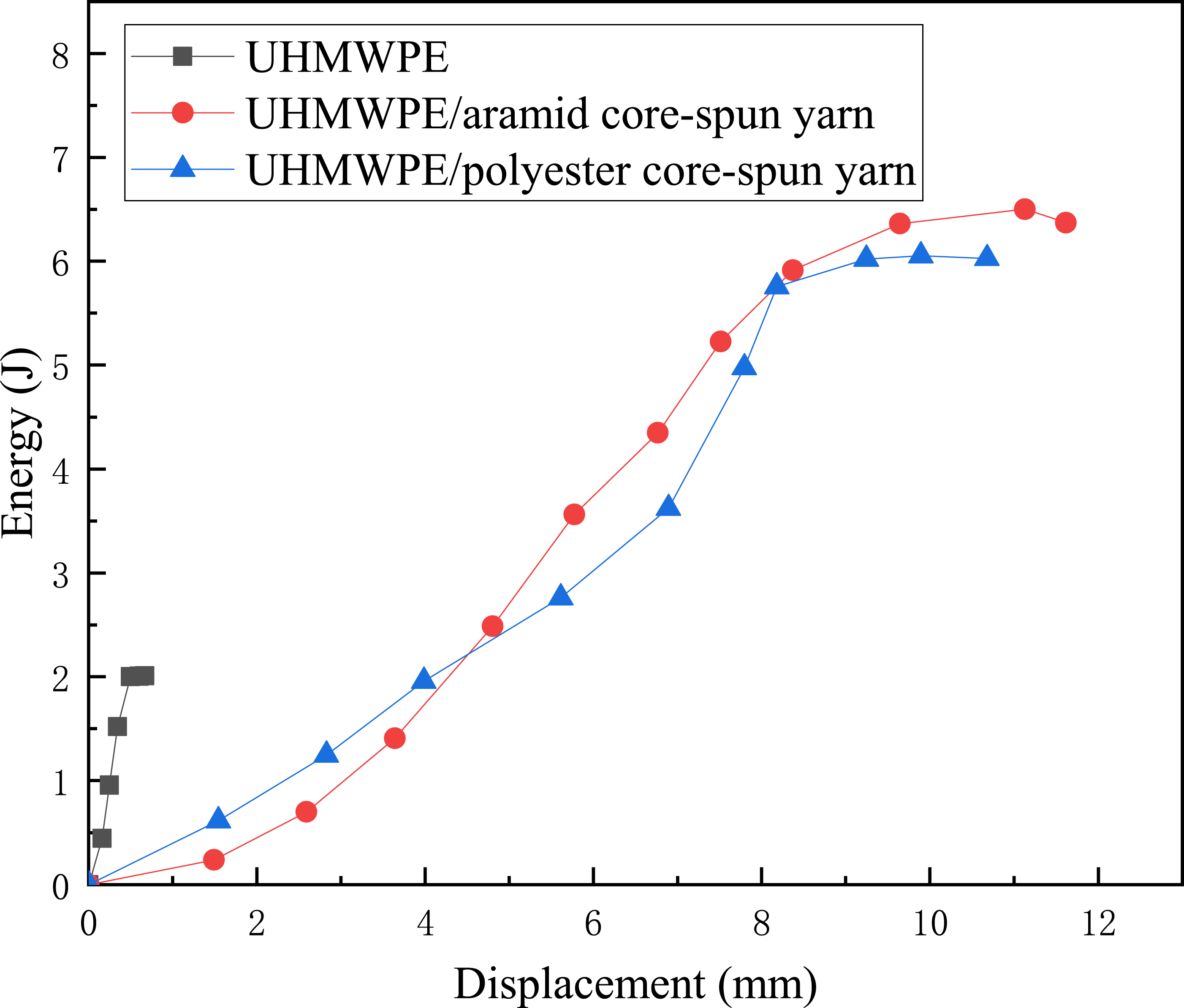

There is a big difference in the energy absorption of the composites after the introduction of these new yarns, and a comparative analysis of the fracture places of the composites was carried out. As shown in Figure 10, the breakage shape at the impact surface of UHMWPE/aramid core-spun yarn and UHMWPE/polyester core-spun yarn composites is relatively thinner compared to that of pure UHMWPE composites, and the material is sheared perpendicular to the perimeter of the impactor with neat ports and less visible fiber plucking at the back side. This result is also shown in the sem diagram (Figure 11), compared with the pure UHMWPE composites, the UHMWPE/aramid core-spun yarn and UHMWPE/polyester core-spun yarn composites basically have no fiber pull-out phenomenon at the damage edge, and the penetration damage of the material occurs in a brittle fracture model, and there is almost no stratification at the fracture, which represents a better bonding degree between the fiber and resin, and no interfacial debonding damage occurs when the material is subjected to impact load. Photographs of composite fracture after low-velocity impact (a), (b) UHMWPE front and back surface (c), (d) UHMWPE/aramid core-spun yarn front and back surface (e), (f) UHMWPE/polyester core-spun yarn front and back surface. Microstructure at fracture after low-velocity impact (a) UHMWPE composite (b) UHMWPE/aramid core-spun yarn composite (c) UHMWPE/polyester core-spun yarn composite.

Conclusion
By studying the impact resistance of the composites after hybridization of UHMWPE with aramid core-spun yarn and polyester core-spun yarn, respectively, based on the best stacking structure of UHMWPE composites, it can be concluded that:
Among the three different stacking structures of UHMWPE composites (0°/90°/0°/90°, 0°/90°/45°/−45° and 45°/0°/90°/−45°), the 45°/0°/90°/−45° UHMWPE composite had the best energy absorption, which was 15% higher than that of the 0°/90°/0°/90° UHMWPE composite, and the 0°/90°/45°/−45° UHMWPE composite had the worst energy absorption, with a 38% decrease compared to the 0°/90°/0°/90° UHMWPE composite.
The energy absorption of the hybrid composites obtained by replacing the second and third layers of the 45°/0°/90°/−45° UHMWPE composites with aramid core-spun and polyester core-pun, respectively, was significantly improved. The energy absorption of the UHMWPE/aramid core-spun hybrid composites and the UHMWPE/polyester core-spun hybrid composites increased by 223% and 202%, respectively.
Under SEM observation, the fracture morphology of the hybridized composites was orderliness compared to all UHMWPE composites, with almost no interface delamination failure phenomenon and relatively small breakage shape. Among the composites with different fiber angles and stacking sequence, the composites with 0°/90°/45°/−45° structures have the most severe breakage and some fiber pullout.
Footnotes
Acknowledgements
Authors sincerely appreciate the support from the Top-notch Academic Programs Project of Jiangsu Higher Education Institutions (TAPP), and the Priority Academic Program Development of Jiangsu Higher Education Institutions (PAPD).
Declaration of conflicting interests
The author(s) declared no potential conflicts of interest with respect to the research, authorship, and/or publication of this article.
Funding
The author(s) disclosed receipt of the following financial support for the research, authorship, and/or publication of this article: This research was supported by School Start-up Fund Project of Changzhou University (grant number: ZMF21020365), by 4th Leading Innovative Talents Cultivation Project of Changzhou City (grant number: CQ20210106), and by the research project of MenBo High-tech Jiangsu Co, Ltd (grant number: 2022K3071).