
Abstract
In this study, a moisture-stimulated three-dimensional printing filament was printed onto an elastic band. The created textile platform changes its shape permanently after exposure to a high-moisture environment. Three main manufacturing parameters – that is, the printed pattern’s infill percentage, the printed pattern’s thickness, and the textile stretch – were tested to study their effects on the platform curving process. It was observed that an increase of the printed pattern’s infill density from 20% to 80%, or the printed pattern’s thickness from 1.3 to 1.7 mm, resulted in reduced curvature, whereas an increase in the elastic band’s stretch extent from 120% to 130% of its original length increased the curvature. The achieved results can be very useful in the design and development of future four-dimensional printed structures, as well as in optimizing and programming moisture sensor performance, as several sensor manufacturing parameters can be modified according to the application and use environment.
Keywords
Three-dimensional (3D) printing has been a revolutionary manufacturing method for the development of complex prototypes and manufacture of goods that cannot be achieved via traditional methods in an easy way, at low cost, or at high speed. Three-dimensional printing is currently used on a wide scale in several industries and household applications.1–3 Recently, the development of 3D printed ‘smart’ materials has resulted in the development of a newer form of printing, which is recognized as four-dimensional (4D) printing. In this form of printing, the finished 3D printed material undergoes a change in its physical and mechanical properties after a certain period of time. This occurs by the response of the 3D printed material to an external stimulus.1,2,4–6 In this manner, 4D printing can be utilized for the development of 3D printed structures, whose properties can be varied or optimized based on the needs of the application. 7
The effects that define the shape change capacities of certain materials with regards to stimuli response can be classified into Shape Change Effect (SCE) and Shape Memory Effect (SME). SCE materials respond to a stimuli almost instantaneously, and the resulting shape change may be temporary, returning to its original shape upon the removal of stimuli, whereas SME materials have a ‘memory’ of a shape, and may return to the ‘memorized’ shape after any further shape change, once a stimulus is applied. Some active materials that are known to have exhibited the SME are Shape Memory Alloys (SMAs) and Shape Memory Polymers (SMPs). Although SMAs take longer to manufacture, they have a low strain value. SMPs can be manufactured by 3D printing methods and are quite responsive to various stimuli, such as temperature, light, magnetism, pH, and electricity.5,8–11 Four-dimensional printing may become influential in various future applications related to biomedical fields (drug delivery systems, customizable stents), soft robotics (including actuators), security, optics, and multidirectional devices.12–14
Fused Filament Fabrication (FFF) is a commonly used form of 3D printing, where preheated extruders deposit thermoplastic in molten form, layer by layer, to develop models previously defined by Computer Aided Design (CAD) models. The deposited molten layer then solidifies, enabling the formation of a solid object.15–21 The FFF form of 3D printing presents certain advantages, such as the ease and flexibility of material handling, the short time the material sits in the heating segment of the extruder, and the possibility of maintaining a continuous process. 19 FFF can be used to modify the mechanical and electrical properties of the printed pattern by modifying the printing parameters, such as the extruder and platform temperature, printing speed, layer height, and the infill patterns and densities of the printed patterns.16,17,22
Poro-lay filament is one of the latest 3D printing materials. It consists primarily of two components, a rubber-based elastomer and a water-soluble Polylactic Acid (PLA). Initially, after being printed, the object prepared remains as a static, hard substance. Upon being immersed in water, however, the PLA portion of the filament dissolves and the rubber-based elastomer remains, resulting in a soft rubber-like behavior of the material.23,24 This material has been recently used to create a moisture sensor based on passive ultra-high frequency (UHF) radiofrequency identification (RFID). The created textile platform changes its shape permanently after exposure to a high-moisture environment, which affects the wireless performance of the RFID tag, and thus provides self-sensing properties based on the wireless read-out of the sensor platform.25,26 In the afore-mentioned publications, the focus has been on the wireless performance of the sensor tag. This study presents a detailed analysis of the effects of varying the manufacturing parameters of such a platform. The goal is to find a way to modify the curving of the platform by modifying the manufacturing parameters, thus later producing a sophisticated method of controlling the performance of 4D printed structures.
Experimental setup
In this study, the elastic band and 3D printed layer were combined to achieve 4D printing performance. The 3D printing material used in this experiment was Poro-lay Lay-Fomm 60, part of the Poro-Lay series of porous filaments. It was 3D printed using a Prenta Duo XL 3D printer. The study was subdivided into three parts: (1) the mechanical properties of the elastic band; (2) the behavior of the Poro-lay Lay-Fomm 60 filament when subjected to water immersion; and (3) the effects of different manufacturing parameters on the textile platform (combination of the 3D printed layer of the Poro-lay Lay-Fomm and the elastic band).
Elastic band stretch test
The elastic band stretch test was done to study the mechanical properties of the elastic band and to get an understanding of how it can be used in the textile platform. The stretch extent of the elastic band and the corresponding tension was studied with the help of a Testometric M500 tensile tester. For this test, a 200-mm specimen of the elastic band was placed between the clamp arms of the testing machine, as shown in Figure 1, and the arms were made to move apart vertically at a speed of 5 mm/s. This test was conducted to observe the behavior of the elastic band for an extension of up to 50%, and to observe any obvious damage or breaking. Further, the change in the thickness of the elastic band when stretched was also measured. The elastic band was placed on a frame, as shown in Figure 2, and its thickness was measured using Vernier calipers.
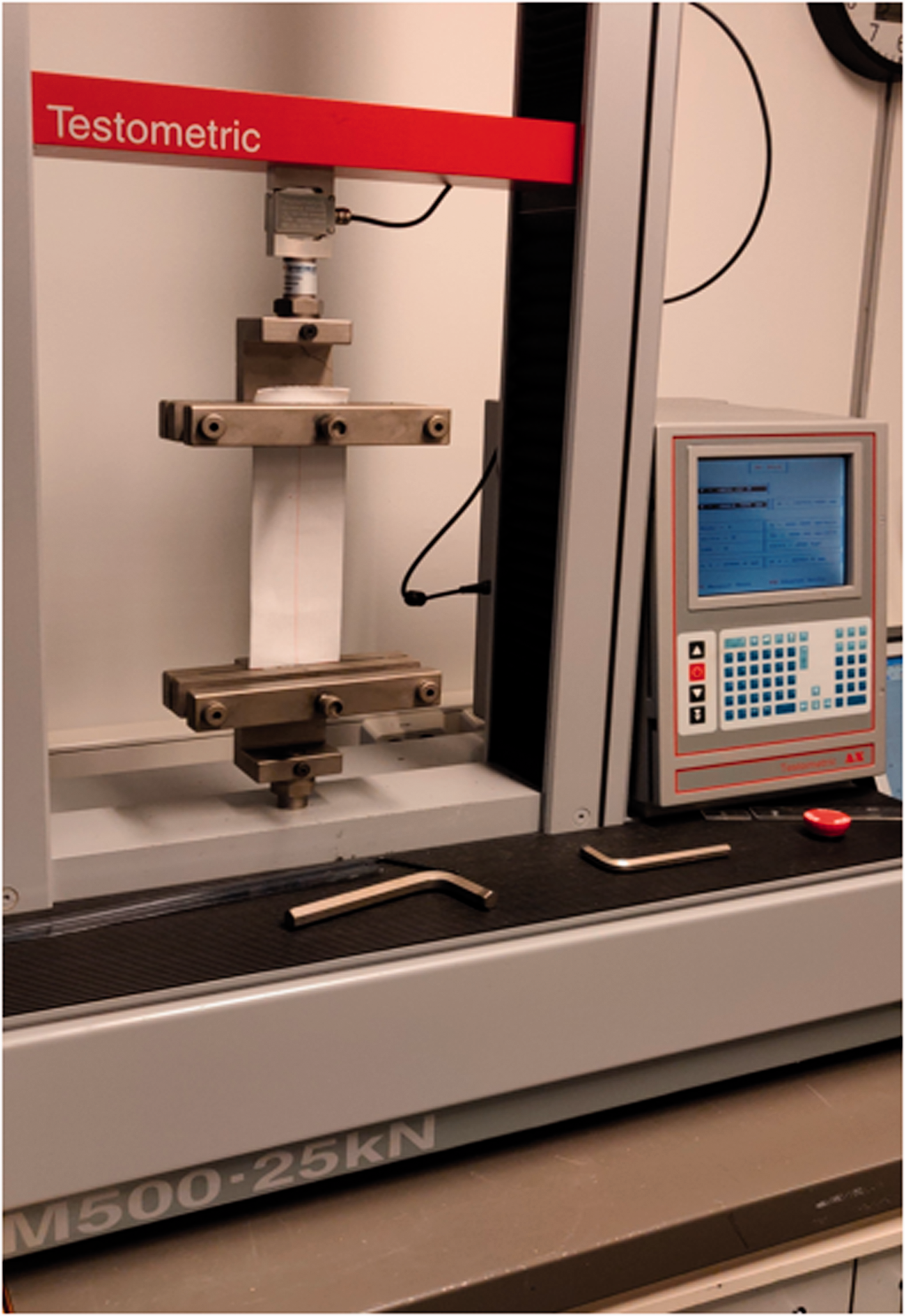
Elastic band stretch test measurement setup.
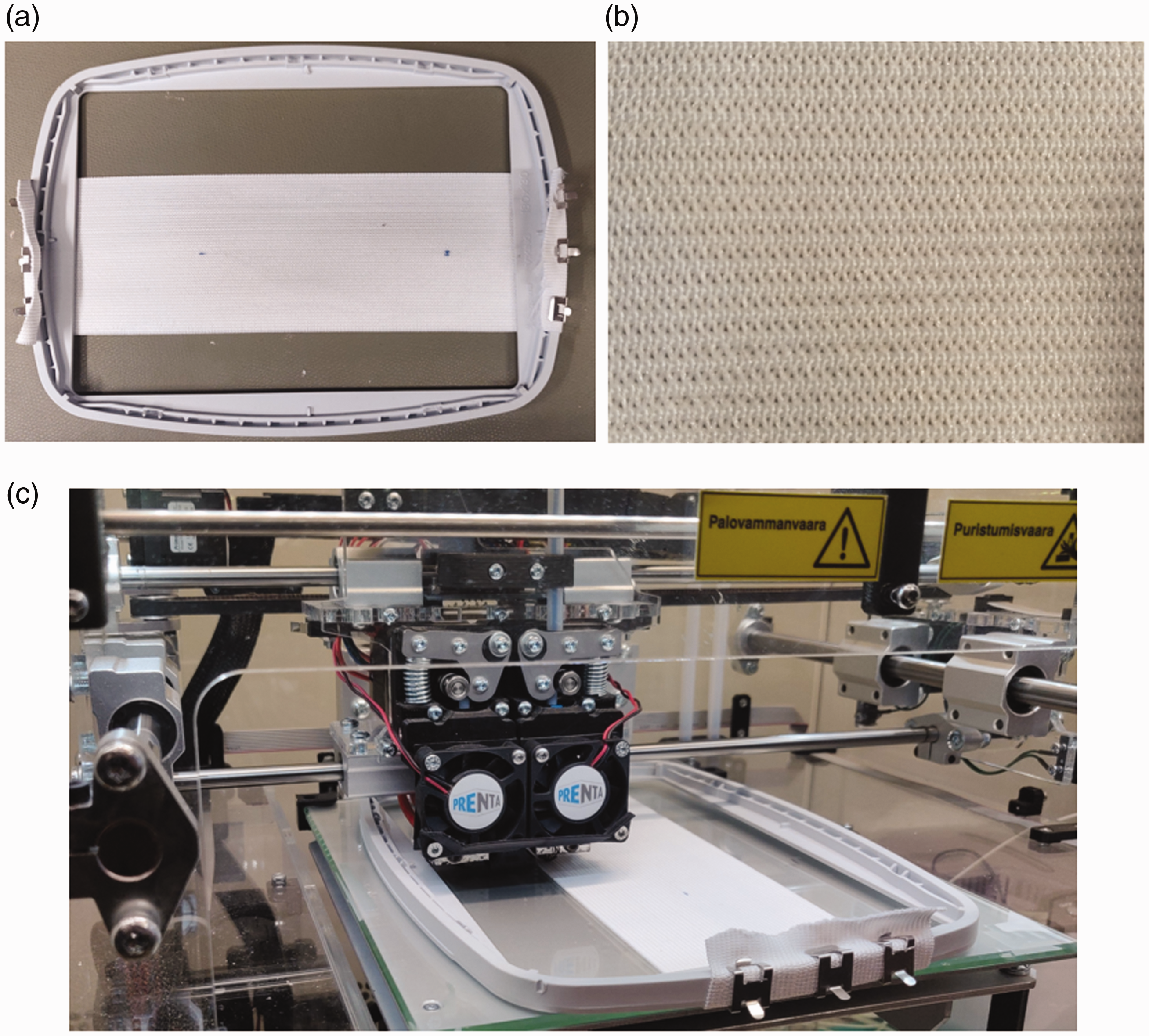
Elastic band mounted on frame (a), close-up image of the elastic band (b), and three-dimensional printing of the Poro-Lay Fomm filament on the elastic band (c).
Three-dimensional printed filament wetting test
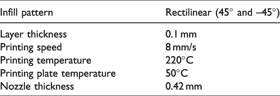
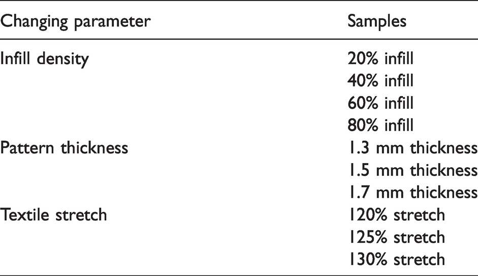
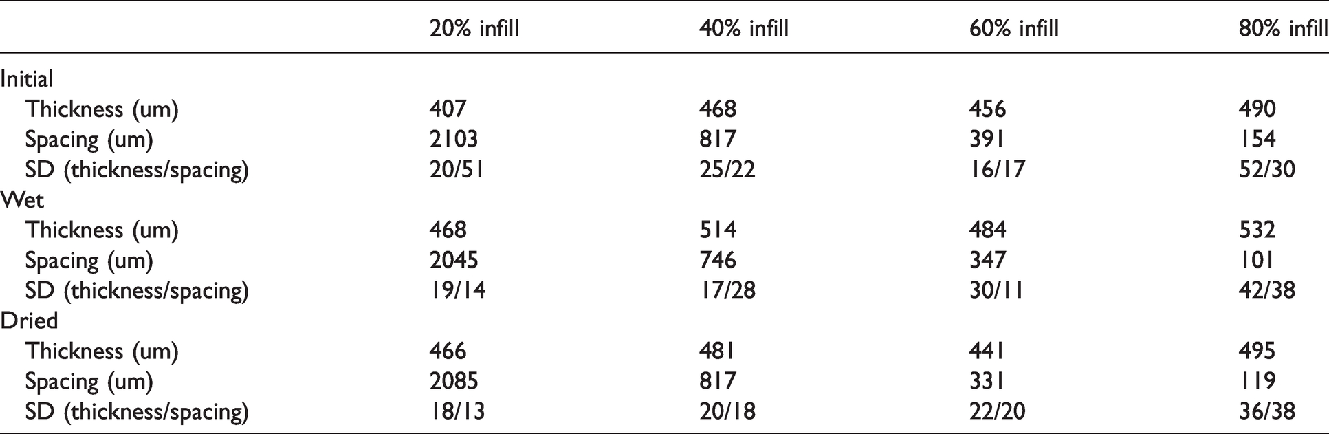
The 3D printed filament wetting test was done to study the effects of water on the Poro-lay Lay-Fomm 60 filament. For this part of the experiment, the behavior of the Poro-lay Lay-Fomm filament when submerged in water was studied with the help of a microscope. As shown in Figure 3, small, square-shaped samples (40 mm × 40 mm × 1.0 mm) with four different infill densities (20%, 40%, 60%, 80%) were prepared. The 3D printing parameters used for the preparation of the square-shaped patterns are listed in Table 1.
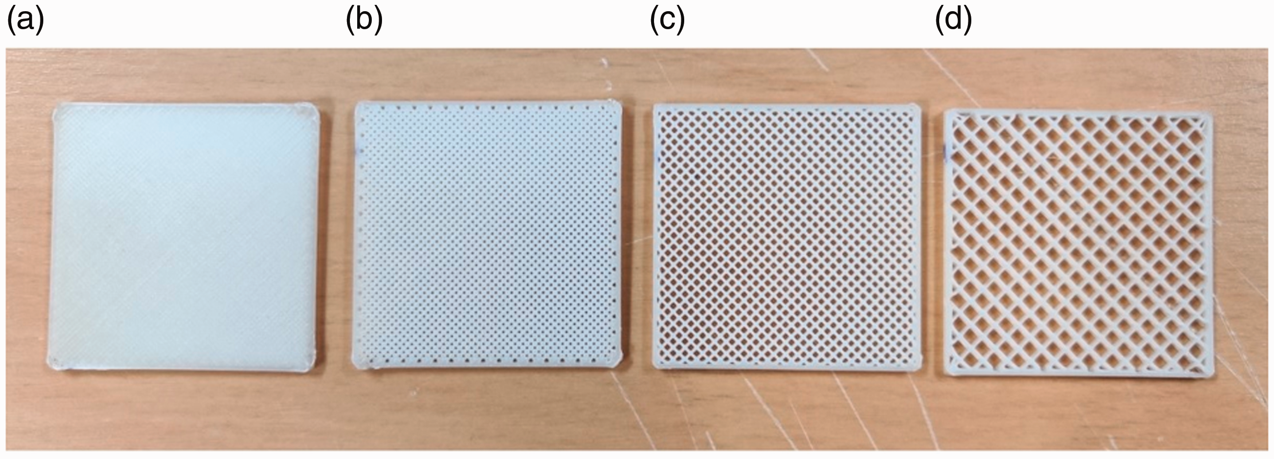
Three-dimensional printed patterns for the wetting test: (a) 80% infill; (b) 60% infill; (c) 40% infill; (d) 20% infill.
Printing parameters of the three-dimensional printed samples presented in Figure 3
The samples were then observed under the microscope at three different stages. Initially, they were observed immediately after the printing process. They were then observed after being submerged in water for 2.5 hours while they were still wet, and finally after being left overnight to dry.
Manufacturing parameters test
The manufacturing parameters test studied the effects of different manufacturing parameters on the textile platform (combination of the 3D printed layer of the Poro-lay Lay-Fomm and the elastic band) curving. The 3D printing parameters for the printing process are similar to the parameters presented in Table 1, with the exception of printing speed, which was maintained at 11 mm/s. This was done because the nozzle of the 3D printer’s extruder was in direct contact with the textile, hence a lower speed of printing would have resulted in the accumulation of the filament around the nozzle, making the printing process difficult.
Firstly, the elastic band was stretched to a specific length with a specific tension force. Next, the stretched band was fixed on a contour frame (as shown in Figure 2), and then the arrangement was fixed on a 3D printing plate, where the 3D printed pattern (130 mm × 40 mm) was fabricated on the elastic band directly. The thickness of the pattern was kept constant at 1.5 mm except for those samples where the sample thickness was the studied parameter. All the tested parameters are shown in Table 2 and 10 samples were fabricated. After the samples were printed, they were immersed in water for 2.5 hours. It was during this stage that the 3D printed part became soft. As the samples dried, the whole arrangement gradually acquired a curved shape.
The studied manufacturing parameters
Results and discussion
Elastic band stretch test
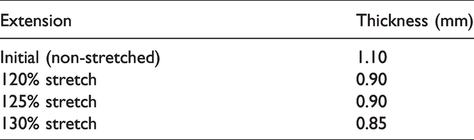
The results of the elastic band stretch test are presented in Figure 4 as a load force versus extension curve. This graph represents the force required for the corresponding extension of the textile. From the graph, the load force required for an extension of 150% (initially a 200-mm specimen) is around 16 N. The force appears to be linear, with slight nonlinear behavior during the extension of the first 20 mm. However, after the test was conducted, it was observed that although the elastic band had permanently extended by a few millimeters after the test, there were no significant signs of damage to it. Based on this result, extensions of 130%, 125%, and 120% were selected for this study, which approximately correspond to forces of around 9.5, 10.7, and 11.7 N, respectively. Table 3 depicts the corresponding change in thickness.
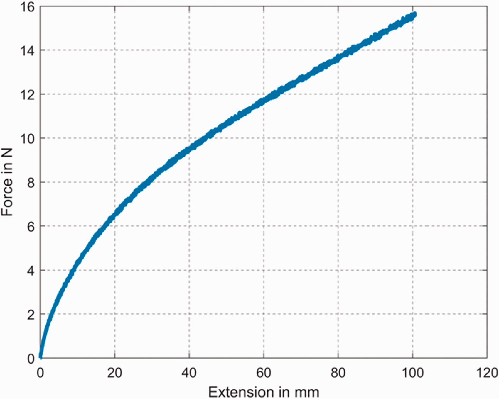
Stretch test (extension versus force) of the elastic band.
Elastic band thickness on extension
Three-dimensional printed filament wetting test
After the 3D printing process, the images of the samples prepared (as shown in Figure 3) were taken at three different stages: initially after the printing process (‘initial’); secondly when they were wet after being submerged in water for 2.5 hours (‘wet’); and finally after they had dried overnight (‘dried’). For the image capture process, six pictures were taken from each of the square-shaped patterns at different positions. The positions selected for the image capture process were kept the same for all three stages. Figure 5 presents the microscopic images of the prepared patterns.
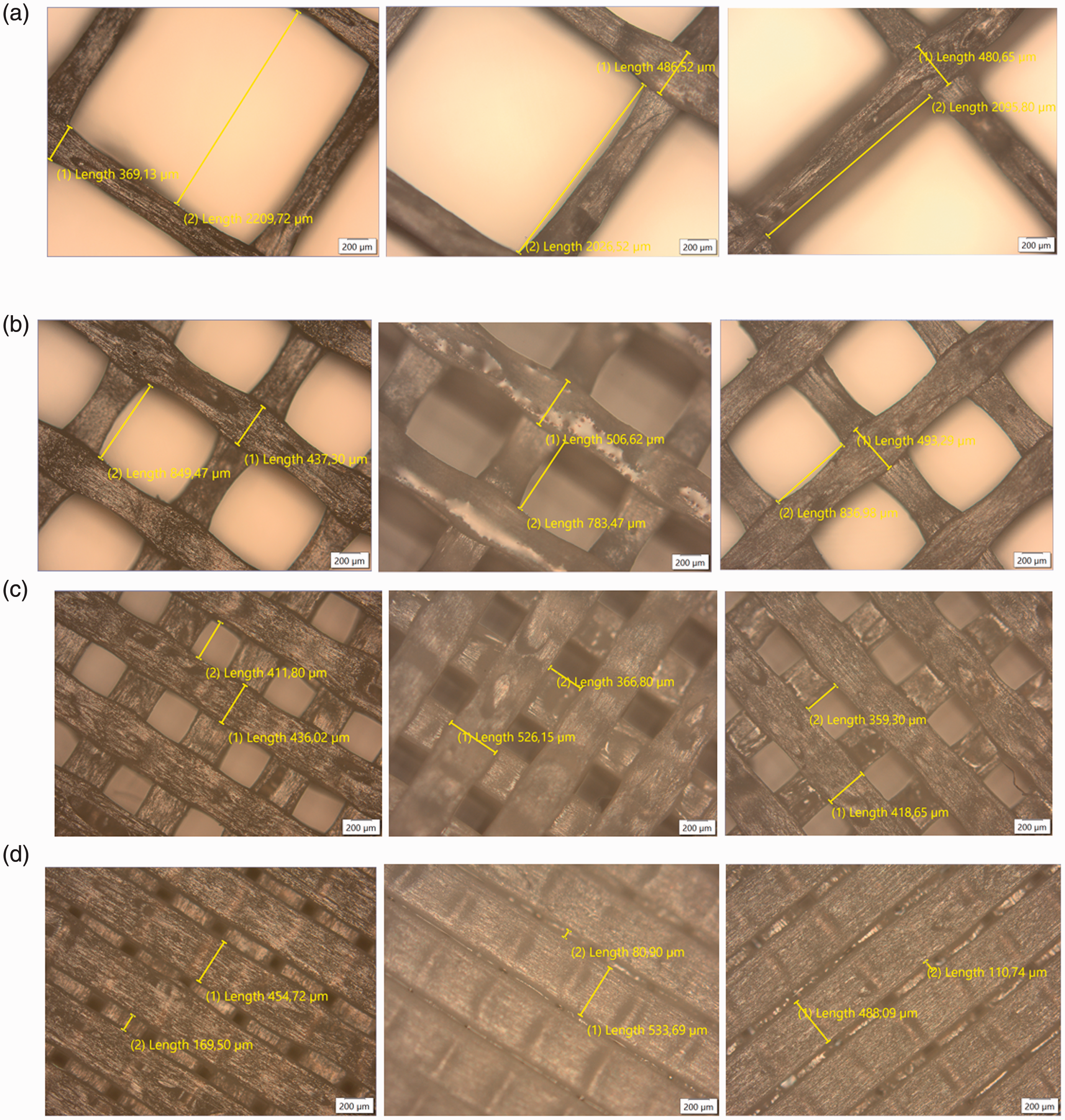
Microscopic images of the three-dimensional printed patterns. (a) 20 % infill: initial (left), wet (centre), and dried (right). (b) 40 % infill: initial (left), wet (centre), and dried (right). (c) 60 % infill: initial (left), wet (centre), and dried (right). (d) 80 % infill: initial (left), wet (centre), and dried (right).
Since six readings from each sample were taken at each state, Table 4 represents the mean of the measured lengths, along with the calculation of Standard Deviation (SD), both rounded to the nearest whole number value. ‘(1) Length’ refers to the thickness of the filament, whereas ‘(2) Length’ refers to the spacing between two strands of the filament. It was observed that when submerged in water, the filament material expanded from its initial thickness, resulting in a seemingly reduced filament spacing and higher filament thickness. After overnight drying, the filament thickness reduced a little for all substrates, and the spacing between the filaments increased for all substrates but the one with 60% printing infill.
Filament thickness and spacing between two strands of the filament in different states
However, there was major variation in the results. The causes of variation in readings can be attributed to human error and some instability arising during the 3D printing process. Firstly, a cause of error could have arisen since when the square-shaped substrates were submerged in water, they became very soft, and after the drying process, they hardened, causing some uplift at the corners. Hence, when they were placed under the microscope, acquiring proper focus in the areas around the corners was quite challenging. Another reason for variations in readings may have been due to the 3D printing process itself. At the microscopic level, we have observed that in some places on the substrate, especially around the top and bottom layers, the filament’s extrusion from the nozzle may not have been uniform.
Manufacturing parameters test
In this experiment, the influence of manufacturing parameters on the curvature of the platform was studied. Several samples of varying 3D printed pattern infill density, 3D printed pattern thickness, and textile stretch were prepared, as listed in Table 2. Firstly, the microscopic pictures in Figure 6 present the adhesion of the 3D printed layer to the elastic band in a sample of 60% infill with an elastic band stretch of 125%. The images below were taken at two points of the printed sample, that is, at one side of the completed 3D printed sample, and secondly, the cross-sectional view of the printed sample after it was cut.
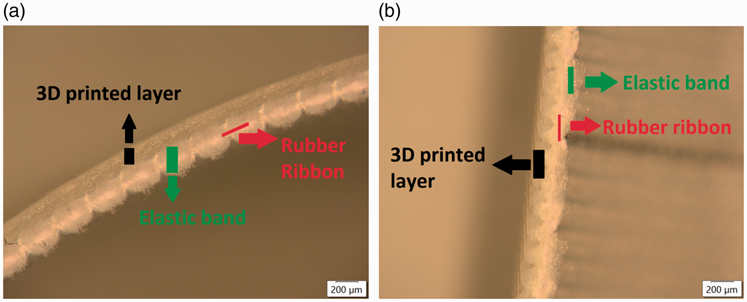
Microscopic view of a three-dimensional (3D) printed layer on an elastic band: (a) side view; (b) front view.
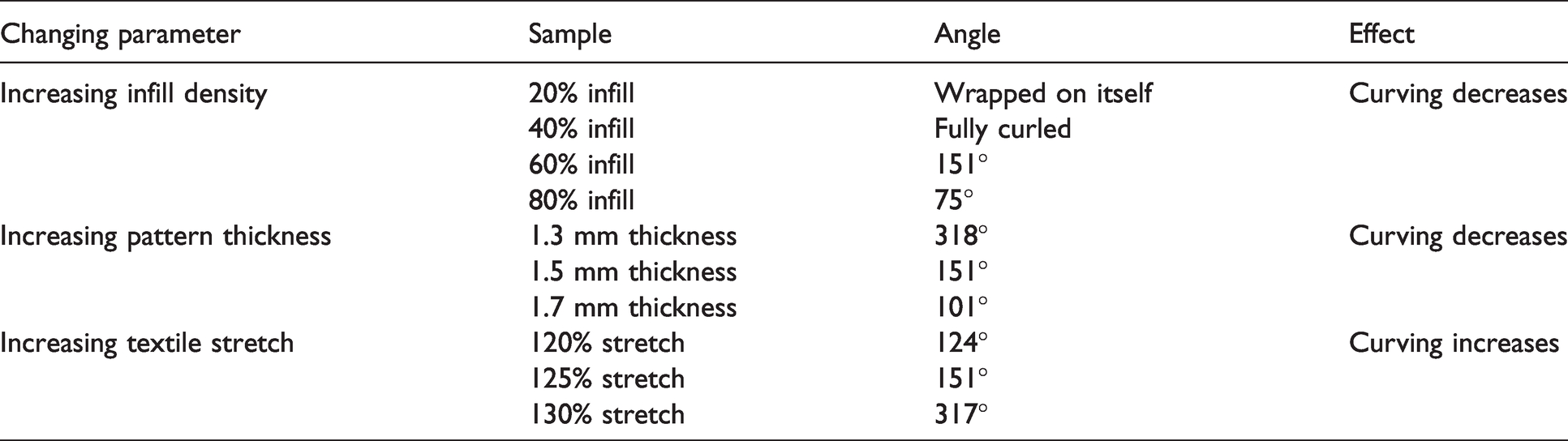
After being printed, the samples were immersed in water for approximately 2.5 hours, after which they were left in the open air overnight until they were totally dry. The angles of the curved samples were recorded from the images using the angle measurement software ‘IC Measure,’ in the manner presented in Figure 7. The approximately estimated angles are presented in Table 5. Figure 8 presents the samples after they were dry.
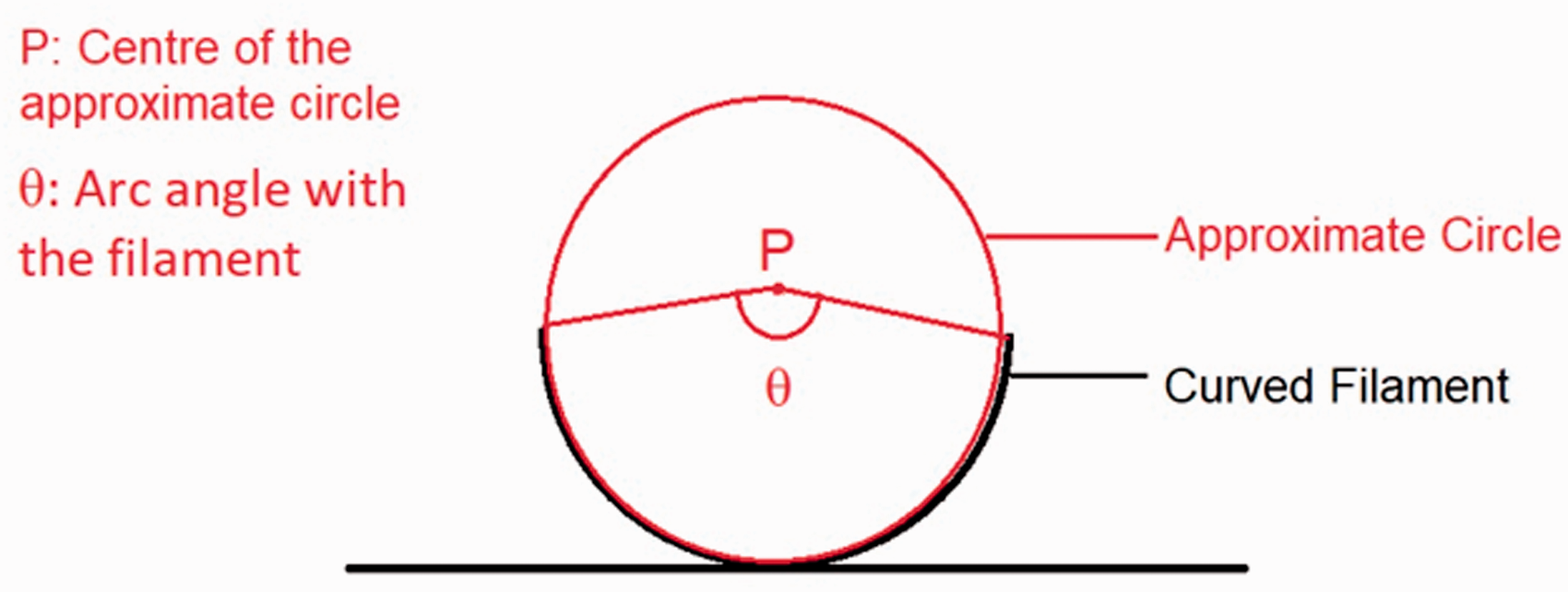
Measurement of angles from the samples.
Summary of the effects of changing parameters
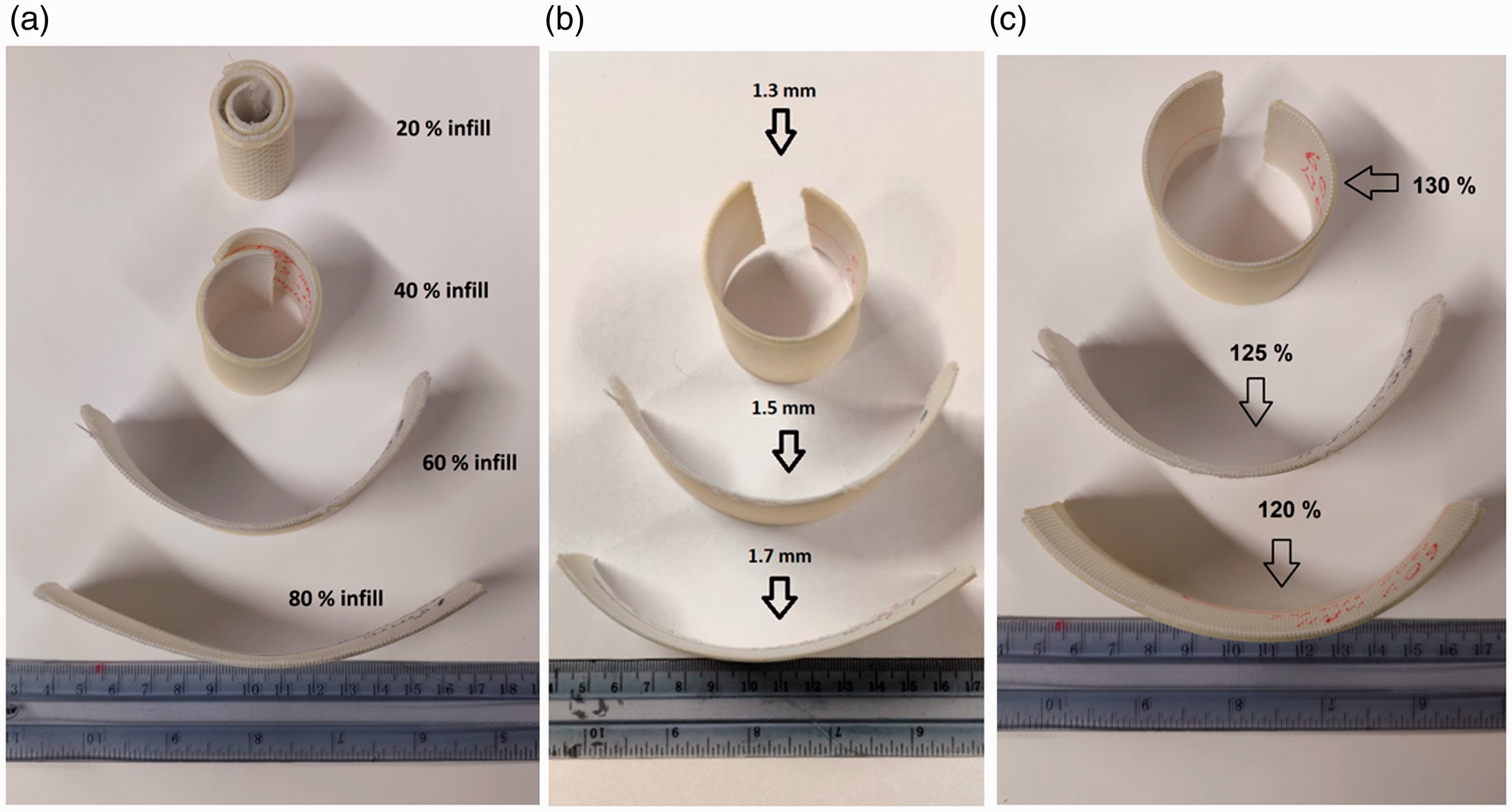
(a) Platform curvatures at varying infill percentages of (from the top) 20%, 40%, 60%, and 80%. (b) Platform curvatures by the three-dimensional printed pattern’s thickness: (top to bottom) 1.3, 1.5, and 1.7 mm. (c) Platform curvatures at varying textile stretch of (top to bottom) 130%, 125%, and 120%.
For the infill density test, the textile’s stretch and 3D printed pattern thickness were maintained at 125% and 1.5 mm, respectively. In this manner, four types of platforms with infill densities of 20%, 40%, 60%, and 80% were prepared. From Figure 8, it is evident that the extent of the platform’s curvature that occurs after drying is dependent on the infill percentage of the printed filament. As can be seen, with the increase of the infill percentage, the samples’ curvature decreased. This is due to the fact that the higher the infill percentage, the stronger the 3D printed pattern. Thus, when the lower infill percentage pattern, which is already a little flexible, gets soft in water, it is not able to resist the elastic band curving.
For the thickness test, the textile stretch was maintained at 125%, and the infill density of the 3D printed pattern was maintained at 60%. In this manner, three samples of 1.3, 1.5, and 1.7 mm thickness each were prepared. From Figure 8, it is evident that the extent of the textile’s curvature that occurs after drying is also directly dependent on the thickness of the 3D printed pattern. From our observation, an increase in pattern thickness implies a decreased curvature. This is due to the fact that the thicker the 3D printed pattern is, the stronger it is. Thus, when the thinner layer, which is already a little flexible, gets soft in water, it is not able to resist the elastic band curving.
For the textile stretch test, keeping the 3D printed pattern’s thickness at 1.5 mm and the infill density at 60%, samples of 120%, 125%, and 130% textile stretch were prepared. From Figure 8, the extent of the platform’s curvature that occurs after drying is also directly dependent on the stretch of the textile upon which the pattern was printed. Our observations show that a higher textile stretch results in a higher curvature. This is due to the fact that a higher stretch causes a higher force to the textile (as presented in Figure 4), which is then released, when the 3D printed pattern gets soft, and is no longer able to hold the elastic band at the stretched state.
Further, Figure 9 shows the platform curving as a response to the 3D printed pattern’s thickness and the platform curving as a response to the varying textile stretch. As can be seen, based on the three measurement spots, an increase in 3D printed pattern thickness corresponds to a decreased curvature, while a higher textile stretch results in a higher curvature. Although there are only three measurement spots and the line cannot be considered linear in either case, the relationship is clear.
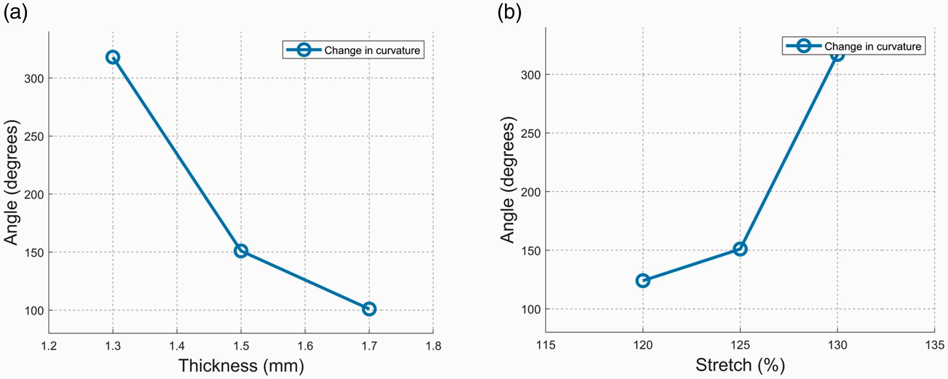
Platform curvature as a response to the three-dimensional printed pattern’s thickness (a) and the textile (elastic band) stretch (b).
It was observed that the substrates printed on the elastic band when wet were very soft, and they hardened after being completely dry. From this, we deduce the fact that since the elastic band was stretched, it tried to regain its original shape during the drying process, which resulted in the curvature as presented in Figure 8. The extent of curve formation during the wetting–drying process varied due to the infill density of the 3D printing pattern, the thickness of the 3D printed layer, and the stretch extent of the textile.
Several challenges were encountered during the development process of the textile platforms. Although efforts were made to keep the stretch extent of the elastic band as precise as possible, slight variations in textile stretch may have occurred. The placement of the clips to hold the textile may have resulted in minute contractions of the textile, which may have affected the extent of the substrate’s curvature. Apart from the above, during the 3D printing process, the formation of the first 3D printed layer was quite challenging, as the nozzle of the 3D printer was in direct contact with the textile. Although not significantly observable, there might have been instances where small portions of the filament did not extrude properly, resulting in missed segments during the printing process. However, despite these challenges and uncertainties, the results about the effects of the studied parameters on platform shape change seem clear. All the fabricated samples with similar manufacturing parameters behaved in an identical way.
Conclusions
In this paper, we studied a 3D printed textile platform, which exhibited a shape change when exposed to moisture After the 3D printing process, the platform was exposed to water for 2.5 hours, and its curving was observed. For the finished 3D printed design, three main manufacturing parameters – that is, the printed pattern’s infill percentage, the printed pattern’s thickness, and the textile stretch – were studied. In our study, the time was a fixed parameter (2.5 hours), and thus our goal was to study the effects of manufacturing parameters on the platform curving during that specific period. Based on the results, it appears that the variation of the infill percentage was the most significant factor in causing the variation of the curvature of the textile platform. An increase in the infill percentage decreased the textile platform’s curvature. However, varying the printed pattern’s thickness and the textile’s stretch also caused significant changes; a lower value of both factors caused a higher extent of curvature. Based on these preliminary results, it is not yet possible to extract a formula for the extent of curvature with manufacturing parameters. However, the results provide a starting point for further research with a larger number of samples, which will enable such a formula to be extracted.
This platform can be very useful in the development of moisture sensors, as highlighted in previous experiments. The results presented in this study can be very useful in optimizing and programming moisture sensor performance, as several parameters of the sensor development can be modified according to specific needs. Interesting novel solutions can be achieved by adding conductive structures into the platform, either by printing conductive inks, embroidering conductive threads, or by filling the porous structure with an ionic liquid. Further, we envision that such programmable textile platforms could be used in smart clothing, for example as clothes that can initiate a response to rain or intense humidity. In addition, certain aspects of this experiment could be extended to the field of soft robotics, where mechanical changes due to moisture can be used to program robotic responses.
Our future goal is to extract a formula for the extent of curvature with different manufacturing parameters. Thus, more testing with a larger number of samples is needed. The next study will be about the mechanical properties of the above-mentioned filament when varying the temperature of the water in which it is immersed and the time it is submerged in water. Further, it is interesting to study the effects of exposure to different relative humidity levels and the effects of cyclic wet–dry testing on the material properties. In addition, the effects of varying the infill pattern of the 3D printed layer can be studied. This could be tested with a uniform infill pattern throughout the structure or printing a variety of infill patterns at every different layer.
Footnotes
Declaration of conflicting interests
The authors declared no potential conflicts of interest with respect to the research, authorship, and/or publication of this article. The authors have no conflicts of interest to declare.
Funding
The authors disclosed receipt of the following financial support for the research, authorship, and/or publication of this article: This work was supported by the Academy of Finland (decision numbers 294534 and 337861).