
Abstract
The passive suspension system based on centralized hydraulic sources suffers from prominent issues such as large space occupancy, low energy efficiency, maintenance difficulties, and insufficient overall performance. To address these issues, this paper innovatively proposes design solutions and control strategies for multiple suspension systems based on distributed hydraulic sources, specifically tailored for heavy-duty special wheeled vehicles. A semi-active suspension system is developed based on both PID control strategy and sky-hook control strategy, which enhances suspension performance under the constraints of limited cost and minimal structural changes. A detailed comprehensive performance simulation model is established, and simulation analysis is conducted under different driving states and road surface conditions. The results indicate that the PID control strategy performs better under dynamic operating conditions such as curves, acceleration, and braking, while the sky-hook control strategy performs better when the vehicle traverses on Class C–F road surfaces. To further enhance the suspension system’s performance, active and slow-active suspension systems are designed. By actively applying control forces, the limitations of the semi-active suspension, which can only respond passively, are overcome. Through the integration of road surface recognition technology, the systems can sense the road surface conditions ahead in real time and convert them into control commands in a feedforward form. This significantly improves the dynamic performance of the suspension system and reduces the performance requirements on posture stabilization devices for onboard weapons and other equipment. In terms of vehicle body deflection, vehicle body acceleration, and dynamic tire load, the relevant indicators for the active suspension are reduced to 2.5%, 7.2%, and 7.3% of those for the semi-active suspension, respectively, while the relevant indicators for the slow-active suspension are reduced to 46.3%, 31.4%, and 31.5% of those for the semi-active suspension, respectively.
Keywords
1. Introduction
With continuous breakthroughs in key technologies such as perception, hybrid power, and automated control, advanced special equipment has entered a rapid development phase, progressively moving towards intelligence, integration, and high performance.1–4 Among them, heavy-duty special wheeled vehicles, known for their high mobility, high-speed travelling capability, high load capacity, excellent off-road performance, and good adaptability to complex terrain, are increasingly becoming a focus of research for scientific institutions and engineering teams worldwide. These vehicles are used in various task scenarios such as tactical maneuvering, material transport, and disaster rescue, and the continuous improvement of their overall performance has become a hotspot in current research.5–10
As the core subsystem of a vehicle chassis, the performance of the suspension directly affects the vehicle’s handling stability, ride smoothness, and ride comfort. A high-performance suspension system should not only provide excellent damping ability but also meet requirements for compact structure, lightweight design, and ease of repair and maintenance. Current research on suspension systems primarily focuses on the application of passive suspension in heavy-duty vehicles,11–15 as well as the recent application of active suspension in high-end passenger vehicles.16–20
Research on passive and semi-active suspensions has attracted extensive attention. Zhu et al. established a simulation model for a single-chamber hydro-pneumatic suspension used in heavy-duty trucks, and analyzed its damping characteristics under both unladen and fully loaded conditions and different damping hole apertures. 21 Li proposed a novel hydraulically interconnected suspension system using an inner and outer dual-floating piston structure, which alleviated the suspension’s performance degradation caused by liquid negative pressure or blockages in the pipeline under co-directional excitation. 22 Yin et al. designed a hydro-pneumatic suspension structure for heavy-duty mining trucks, which adjusted suspension stiffness and damping by controlling the high-speed switching of electromagnetic valves. 23 Zhang et al. integrated a hydraulic inertial device with a hydro-pneumatic spring, utilizing a spiral channel to connect two chambers. This approach enables high-speed flow of liquid with significant inertia between the two chambers, effectively improving suspension performance. 24 Sung et al. proposed a novel semi-active suspension system for military vehicles, and employed a sky-hook control strategy that reduced the vertical displacement and acceleration of the sprung mass by approximately 27%, effectively improving vehicle comfort. 25 Sun et al. applied back propagation-active disturbance rejection control to a hydro-pneumatic suspension, reducing the weighted acceleration of seats by 14.67%, which significantly improved ride comfort. 26 Gong et al. proposed a variable-damping suspension and control strategy for heavy-duty vehicles, which adjusted the suspension damping by controlling the safety valve opening pressure, thereby significantly improving the vehicle’s handling stability and comfort. 27 Ihsan et al. combined the sky-hook control algorithm with the ground-hook control algorithm to create a hybrid control algorithm, aiming for a trade-off control effect between maneuverability and comfort. 28 Savaresi et al. used a frequency-dividing algorithm to apply the sky-hook control algorithm and acceleration-driven damping algorithm to different vibration frequency bands. This hybrid control algorithm achieved better control effects than single control algorithms. 29 Lu et al. designed a new hydraulically interconnected suspension that could adjust the pitch and roll stiffness for different vehicle types, loads, and driving habits, achieving a 30% overall performance improvement compared to traditional air springs. 30 Xu et al. used PID control, adaptive fuzzy control, and compound parallel control to conduct simulation analysis based on a 1/4 vehicle model, and compared the ride comfort of different control strategies under step excitation. 31 Jin et al. proposed a two-stage semi-active suspension structure and analyzed the effects of different control strategies on vehicle body acceleration and dynamic tire load. 32 Xiao et al. proposed an anti-roll electro-hydraulic suspension and used an optimal control scheme to calculate the anti-roll torque and control the servo valve. As a result, the roll angle and lateral axle load transfer rate were effectively reduced, and the suspension’s handling stability was enhanced. 33 Li et al. proposed a motor-driven dual-chamber hydro-pneumatic suspension and adjusted the air volume entering the main air chamber through a motor lead screw structure to control the suspension height. Compared to passive suspension, the root mean square reduction of pitch and roll angles of this suspension exceeded 50.46%. 34 Ji et al. proposed a semi-active suspension control strategy based on a deep neural-fuzzy system and conducted simulation analysis under different working conditions, demonstrating the strong adaptability to road surfaces of this control strategy. 35 Ren et al. combined sky-hook and ground-hook control to develop a hybrid control algorithm for semi-active suspensions. Simulation tests on random road surfaces showed that this suspension system ensured both comfort and good maneuverability. 36
Researchers have also conducted studies on active suspension systems. Chen et al. developed a sliding mode control strategy with active disturbance rejection to improve the vertical stability of the hydro-pneumatic suspension for unmanned vehicles. Under random road conditions, compared to passive suspension, the root mean square values of vehicle body acceleration and displacement were reduced by approximately 26.9% and 29.3%, respectively, and the system showed strong robustness under varying vehicle body load conditions. 37 Yang et al. proposed an adaptive control method for a multi-axle heavy-duty wheeled vehicle equipped with an electro-hydraulic actuator active suspension. Compared to hydro-pneumatic suspension and multi-objective control strategies, this suspension improved the roll angle, yaw angle, and vehicle body acceleration to varying degrees. 38 Pang et al., based on estimated road information, achieved real-time adjustment of control objectives by changing the weighting coefficients, thereby enabling the switching control between ride comfort and roll stability. 39 Nguyen et al. proposed an active suspension controlled by an optimized sliding mode control algorithm. Under sinusoidal wave excitation, compared to passive suspension and PID control algorithms, the root mean square of vehicle body displacement was reduced by 87.5% and 30%, respectively, while under random excitation, the root mean square of vehicle body displacement decreased by approximately 90% and 30%. 40 Liu et al., considering road gradients, proposed an active suspension model for three-axle heavy-duty vehicles, and designed an energy-saving backstepping tracking control method based on an ideal reference model and observer. Simulation and test results showed that the proposed controller outperformed passive suspension and existing controllers in terms of damping performance and energy consumption. 41 Bai et al. adopted a fuzzy PID control strategy for an active air suspension used in a 6×4 heavy-duty vehicle. When the vehicle traveled at a speed of 60 km/h on a Class A road surface, the vertical acceleration of the vehicle body was reduced by 22.1%, thus effectively improving comfort. 42 Chen et al. designed an active-passive hybrid suspension actuator for emergency rescue vehicles to improve their ride comfort and handling stability on complex roads, reducing the maximum recovery damping force and compression damping force to 53.5% and 50.4% of those in passive suspension, respectively. 43
Although significant progress has been made in suspension structure design, control strategy optimization, and performance improvement, most of the current studies still rely on centralized hydraulic sources or traditional hydro-pneumatic systems, which suffer from high system complexity, limited response speed, and other issues. Moreover, the design and performance analysis of active suspension systems for heavy-duty special wheeled vehicles are still relatively scarce. To better meet the higher requirements for overall performance of such vehicles in complex task environments, there is an urgent need to explore suspension system architectures with modular structures, higher integration, and stronger adaptability, along with their control strategies, and to conduct more systematic comparative analysis of their comprehensive performance.
This study focuses on addressing the disadvantages of vehicle-mounted integrated hydraulic source architectures, such as large spatial occupation, excessive weight, poor maintainability, significant energy transmission losses, and difficulty in achieving high-frequency and precise control. To overcome these limitations, the design and control strategies of semi-active and active suspension systems based on distributed hydraulic sources are developed, and comprehensive performance simulations and comparisons are conducted under various operating conditions. Relevant findings lay a solid technical foundation for the further development of high-performance suspension systems for heavy-duty special wheeled vehicles. Section 1 introduces the basic performance requirements for the suspension system of a certain heavy-duty special wheeled vehicle. Section 2 analyzes the limitations of centralized hydraulic source architectures on suspension performance. In Sections 3 and 4, the design and control strategies of semi-active, active, and slow-active suspension systems based on distributed hydraulic sources are studied, and the suspension performance under different driving states and road surface conditions is simulated and analyzed. Section 5 provides a comparative analysis of the comprehensive performance of the aforementioned suspension systems. Finally, Section 6 offers a conclusion.
2. Basic performance requirements for the suspension system
In this paper, design solutions and control strategies for the suspension system of a certain heavy-duty special wheeled vehicle are studied. The basic performance requirements proposed for the suspension system of this heavy-duty special wheeled vehicle are summarized as follows: (1) Eight-wheel independent suspension system, with a total sprung mass of 19 tons and an unsprung mass of 4 tons; (2) The working pressure of the hydraulic system does not exceed 25 MPa; (3) The working stroke of the suspension system is no less than 300 mm; (4) Under static conditions, the maximum output speed of the suspension is no less than 15 mm/s, and the output force is no less than 40 kN at this point; (5) Under static conditions, the maximum output force of the suspension is no less than 75 kN, and the output speed is no less than 8 mm/s at this point; (6) Safe driving capability on 35° longitudinal slopes with vehicle posture adjustment; (7) Safe driving capability on 25° lateral slopes with vehicle posture adjustment; and (8) Obstacle-crossing capability with a crossing height of at least 1,000 mm.
3. Constraints on suspension system performance by centralized hydraulic source architectures
Currently, China’s first-generation heavy-duty wheeled vehicle is equipped with a suspension system based on a centralized hydraulic source, where a large hydraulic pump station delivers hydraulic energy to eight sets of hydro-pneumatic suspensions through multiple high-pressure pipelines.
During development and testing, it was observed that although the centralized hydraulic suspension system provides strong load support and static vehicle posture adjustment, it still faces several significant challenges: (1) The hydraulic pipelines are distributed throughout the vehicle, interspersed between various sections and structural spaces, which not only greatly increases the integration difficulty of the system but also imposes significant restrictions on the overall vehicle structure design. (2) The large hydraulic pipeline network, heavy valve groups and actuator components, and complex sealing requirements reduce system reliability and maintainability. (3) The centralized hydraulic system experiences significant energy transmission losses during operation, especially in long-distance, high-complexity piping scenarios. (4) The hydraulic system’s dynamic response is constrained by the capabilities of the hydraulic pump station, making it difficult to achieve high-frequency and precise control, thus limiting the adaptive capability of the suspension system in complex battlefield environments. (5) With the growing emphasis on lightweight, compactness, maintainability, and high mobility in modern special vehicles, the centralized hydraulic system gradually reveals many shortcomings.
The figure below shows the actual installation of the centralized hydraulic source and its piping in the first-generation heavy-duty wheeled vehicle (Figure 1). Physical diagram of the centralized hydraulic source and its piping of the first-generation heavy-duty wheeled vehicle.
To address these issues, a suspension system architecture with a modular, distributed drive is proposed in this paper, significantly improving system modularity, scalability, and maintainability.
The distributed drive suspension system can utilize either electro-hydrostatic actuators or electro-mechanical actuators. Through modular design, the system eliminates the need for a massive hydraulic pipeline network and greatly reduces system weight and spatial occupation, while enabling active suspension adjustment. This results in improved ride comfort, handling stability, and off-road performance for the vehicle. However, electro-mechanical actuators, with their main load-bearing component—the planetary roller screw pair—having poor shock resistance, are not suitable for suspension systems. In contrast, the electro-hydrostatic actuator architecture is an optimal choice for the next-generation suspension system.
4. Semi-active suspension system based on distributed hydraulic sources
Considering the operating conditions of heavy-duty special wheeled vehicles, a dual-chamber hydro-pneumatic spring is adopted as the suspension in this paper due to its excellent smoothness and stability, and its ability to adapt to various complex road conditions and high loads. The structural schematic diagram and 3D model of the dual-chamber hydro-pneumatic spring are shown in Figure 2. Structural schematic diagram and 3D model of dual-chamber hydro-pneumatic spring.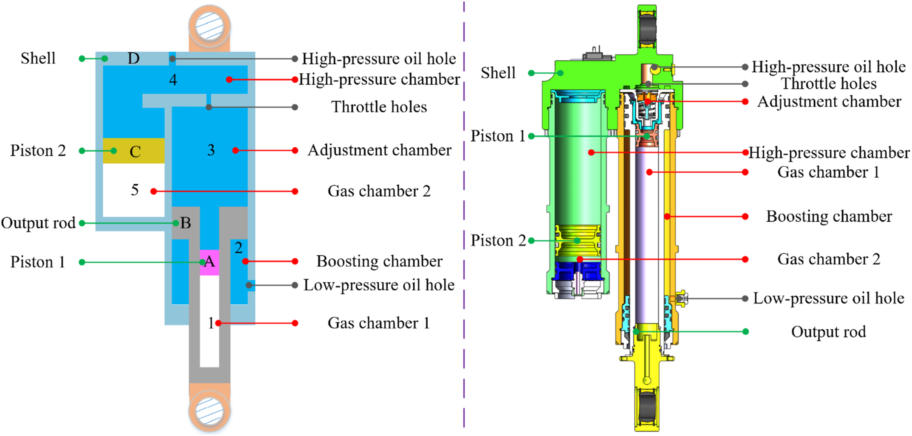
The dual-chamber hydro-pneumatic spring mainly consists of gas chamber, hydraulic oil chamber, piston, and output rod, with the hydraulic oil serving as the transmission medium and the gas acting as the elastic medium. When the vehicle is subjected to road excitations, the vertical motion of the suspension drives the piston to push the hydraulic oil. Due to the incompressibility of the oil, the force is transmitted to the gas chamber, compressing the gas and generating an elastic restoring force, thereby providing the damping effect.
A set of small servo motors, gear pumps, valve groups, and integrated oil tanks is equipped with each hydro-pneumatic spring to replace the centralized hydraulic system. This effectively reduces energy loss, improves response speed, eliminates complex pipelines, reduces volume and weight, and enhances flexibility and maintainability. The semi-active suspension system possesses vehicle posture adjustment capabilities, but due to the limited output capacity of servo motors and pumps, it still optimizes the vehicle’s ride smoothness and stability by adjusting damping through throttle holes, and full active output is not yet achievable.
4.1. Hydraulic cylinder
Under the condition of meeting the required output force, the hydraulic cylinder bore should be as small as possible. The initial hydraulic bore diameter D1 is 80 mm, and the output rod diameter D3 is 60 mm. The initial pressure Pd2 of the boosting chamber is set to 1 MPa. With the mechanical efficiency ηm1 of 97% and volumetric efficiency ηv1 of 98%, the hydraulic cylinder’s maximum output force FHP required at the working pressure Pd1 is 75 kN, so:

Therefore, the working pressure of the hydraulic cylinder should be at least 16.2 MPa. Since distributed hydraulic sources are used, the pipeline pressure loss from the hydraulic pump to the hydro-pneumatic suspension is minimal, estimated at 1 MPa. Thus, the system working pressure is selected to be 18 MPa.
The typical material for the hydraulic cylinder is 30CrMnSiA, with tensile strength σb of 1,080 MPa, yield strength σs of 885 MPa, and elastic modulus E of 206 GPa. For a cylinder barrel with a wall thickness not exceeding 0.3 times its inner diameter, the wall thickness δ2 of the cylinder barrel can be calculated using the maximum tensile stress theory, i.e., the middle diameter formula for thin-walled cylinders:

The hydraulic cylinder adopts a single-rod asymmetrical structure, which is shorter. Due to the volume difference between the high-pressure and low-pressure chambers, a small oil tank is required. The oil tank is installed next to the hydro-pneumatic suspension, which generates minimal pipeline losses. The minimum volume Qz of the boosting oil tank can be calculated as:

Based on the cylinder dimensions, maximum linear speed vmax, mechanical efficiency ηm1, and volumetric efficiency ηv1, the maximum flow rate qm of the hydraulic cylinder can be calculated:

4.2. Hydraulic pump
A gear pump is selected as the hydraulic pump due to its advantages such as simple structure, ease of manufacture, low cost, operating reliability, insensitivity to hydraulic fluid pollution, and ease of installation and maintenance. The gear pump converts the mechanical energy of the servo motor into hydraulic energy, providing pressure and fluid to the suspension system.
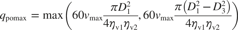
In addition to entering the hydraulic cylinder, a small portion of the flow output by the gear pump is lost in the valve block, mainly due to leakage from various functional valves, pressure losses along the path, and local pressure losses. Taking the mechanical efficiency ηm2 and volumetric efficiency ηv2 of the valve block as 95% respectively, the maximum output flow qpomax of the hydraulic pump is:
A CBU-F series gear pump from Jiangsu Vibo Hydraulics Joint Stock Co., Ltd. is selected, with a maximum speed npmax of 6,000 rpm, rated pressure of 20 MPa, maximum pressure of 25 MPa, volumetric efficiency ηv3 of 95%, and mechanical efficiency ηm3 of 90%. The displacement of the gear pump should be larger than:

Thus, a gear pump with a displacement Vpo of 0.88 ml/r can be selected.
4.3. Servo motor
At the maximum linear speed of 15 mm/s, the maximum output flow of the gear pump is 4.86 L/min. The maximum speed npo1 of the gear pump at this point is:

At this operating point, the output force FEHA1 of the output rod is 40,000 N, and the hydraulic cylinder pressure Pmin is calculated as:

The servo motor speed nmout1 is equal to the gear pump speed npo1, and considering a 1 MPa pressure loss, the minimum output torque THout1 of the servo motor is:

At the minimum linear speed of 8 mm/s, the output flow qpomin of the gear pump is:

At this point, the gear pump speed npo2 is:

At this operating point, the output force FEHA2 of the output rod is 75,000 N, and the system’s pressure difference Pmax is:

The servo motor speed nmout2 is equal to the gear pump speed npo2, and considering a 1 MPa pressure loss, the maximum output torque THout2 of the servo motor is:

When high-frequency sweep or high-acceleration performance is not considered critical, a high-power-density motor developed by our research group can be used. Its rated speed nm is 4,500 rpm, maximum speed nmmax is 6,000 rpm, rated torque Tout is 2.0 Nm, and peak continuous torque Toutmax is 3.1 Nm.
4.4. Simulation model
To analyze the comprehensive performance of the semi-active suspension system, a simulation model was established in AMESim, as shown in Figure 3. Simulation model of passive/semi-active suspension.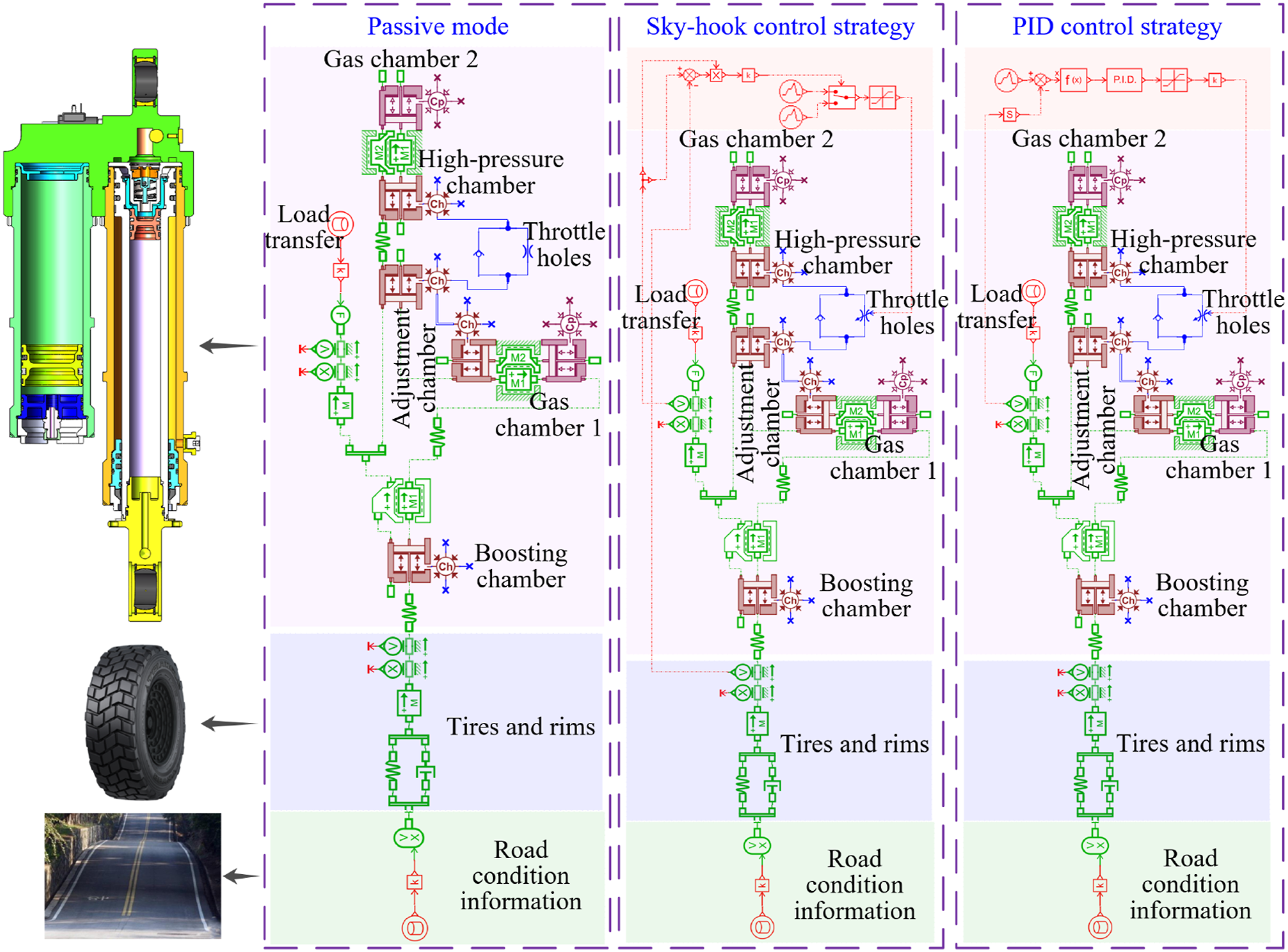
To achieve more optimal damping performance while ensuring the vehicle’s ride smoothness and stability, the initial pressure of the boosting chamber was set to 1.1 MPa, and the initial pressures of the remaining chambers were set to 5.5 MPa, based on extensive preliminary simulation analyses. Four parameters were selected to assess the vehicle’s ride smoothness and stability: Vehicle Body Deflection (BD), Vehicle Body Acceleration (BA), Dynamic Tire Load (DTL), and Suspension Dynamic Deflection (SDD).
To analyze the comprehensive performance of the suspension system under different driving states and road surface conditions, simulations were carried out according to the following timeline: (a) 0s–2s: The vehicle drives at a constant speed on a flat road. (b) 2s–5s: The vehicle passes through a curve (or accelerates/brakes), causing a 7.5 kN increase in the spring load of the suspension due to load transfer. The vehicle then returns to its initial motion state after 2 seconds. (c) 8s–12s: The vehicle drives at 25 km/h over a Class F road surface. (d) 14s–17s: The vehicle passes through a curve (or accelerates/brakes), causing a 7.5 kN decrease in the spring load of the suspension due to load transfer. The vehicle then returns to its initial motion state after 2 seconds. (e) 20s–28s: The vehicle sequentially climbs a 200 mm vertical obstacle and encounters a 200 mm sudden change in road surface position.
4.5. Performance analysis
4.5.1. Performance of the passive suspension system
First, simulation analyses were conducted for the passive suspension system based on a centralized hydraulic source, which is currently installed in the first-generation heavy-duty wheeled vehicle. The results are shown in Figures 4–7. (a) When the spring load increases, the Vehicle Body Deflection change in the large damping hole state is approximately twice that in the small damping hole state. The Vehicle Body Acceleration and the Dynamic Tire Load are low in both states. However, the Suspension Dynamic Deflection change in the large damping hole state is approximately 2.3 times that in the small damping hole state. When the spring load decreases, the comprehensive performance in the two damping hole states differs slightly. This indicates that, when the vehicle passes through a curve or accelerates/brakes, there is no significant difference in ride smoothness between the two damping hole states, while the small damping hole state provides better handling stability. (b) When the vehicle travels at 25 km/h over a Class F road surface, the root mean square values of the Vehicle Body Deflection, the Vehicle Body Acceleration, the Dynamic Tire Load, and the Suspension Dynamic Deflection in the small damping hole state are 32.8 mm, 5,867 mm/s2, 15,121.7 N, and 8.6 mm, respectively. In the large damping hole state, these values are 23.4 mm, 3,116 mm/s2, 8,020.0 N, and 11.5 mm, respectively. This indicates that, when the vehicle travels on a road with higher roughness, the large damping hole state offers better ride smoothness. (c) When the vehicle encounters a sudden change in road surface position, the vibration amplitude of the Vehicle Body Deflection in the small damping hole state is larger than that in the large damping hole state. When the vehicle travels under such road conditions, the root mean square values of the Vehicle Body Acceleration, the Dynamic Tire Load, and the Suspension Dynamic Deflection in the small damping hole state are 3,002 mm/s2, 7,745.8 N, and 3.7 mm, respectively. In the large damping hole state, these values are 1,705 mm/s2, 5,393.2 N, and 7.1 mm, respectively. This indicates that, when the vehicle encounters an elevation, descent, or sudden change in road surface position, the large damping hole state provides better ride smoothness. Simulation results for vehicle body deflection in passive suspension. Simulation results for vehicle body acceleration in passive suspension. Simulation results for dynamic tire load in passive suspension. Simulation results for suspension dynamic deflection in passive suspension.


4.5.2. Performance of the semi-active suspension system
From the previous analysis, it was observed that the passive suspension system exhibits poor robustness on different road surface conditions. To further enhance system performance, a semi-active suspension system was developed, and both the PID control strategy and the sky-hook control strategy were adopted. Simulation analyses were conducted under the same timeline, and the results are shown in Figures 8–11. Simulation results for vehicle body deflection in semi-active suspension. Simulation results for vehicle body acceleration in semi-active suspension. Simulation results for dynamic tire load in semi-active suspension. Simulation results for suspension dynamic deflection in semi-active suspension.


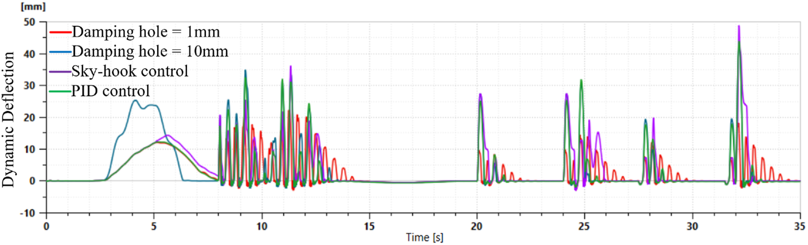
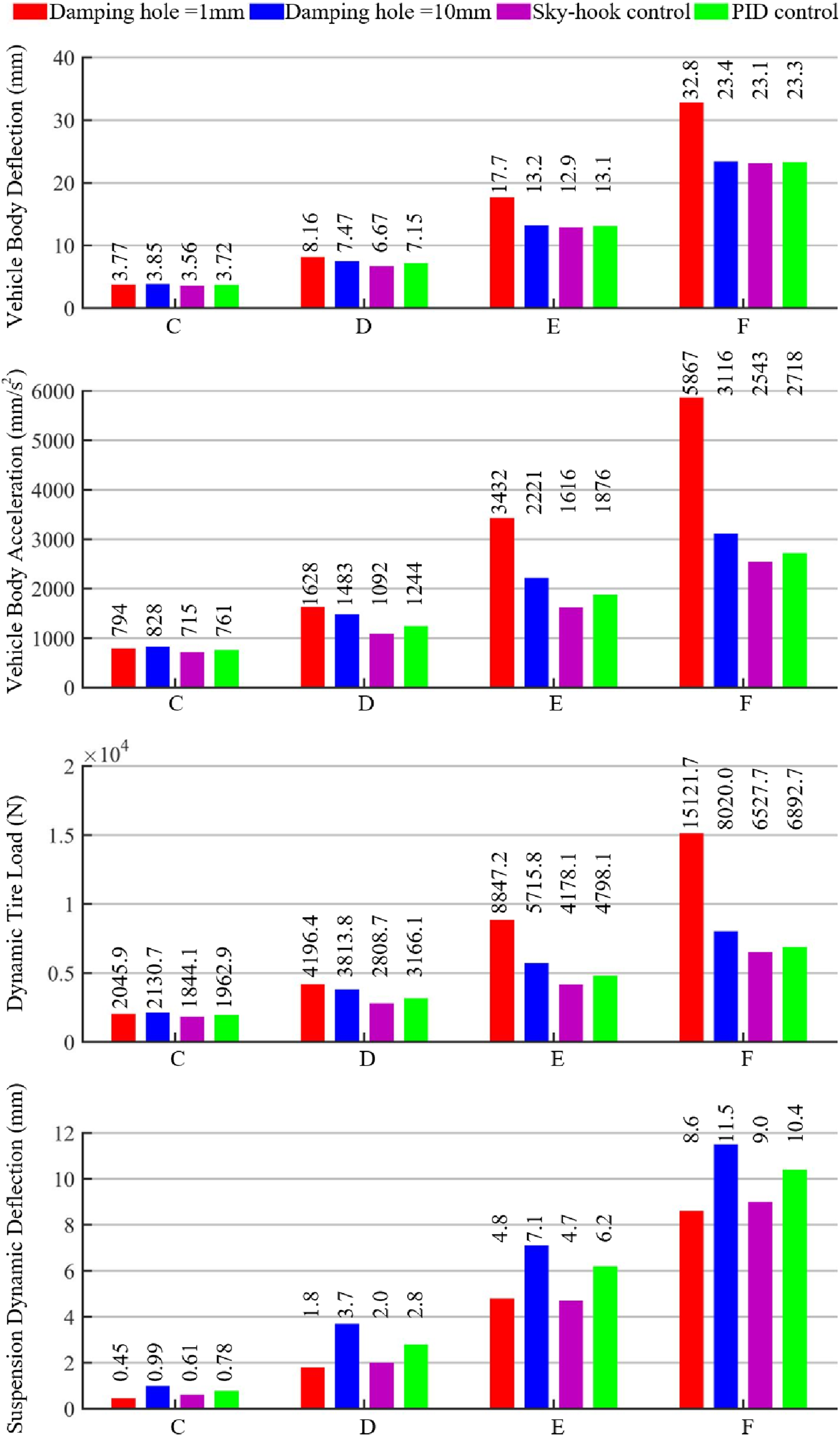
The PID and the sky-hook control strategies are two of the most widely applied methods in semi-active suspension research. They are characterized by their ease of implementation and practical feasibility, and have therefore been extensively adopted by many researchers. The Sky-hook control strategy is designed based on the relative velocity between the vehicle body and the unsprung mass. When the relative velocity of the two has the same direction, a larger damping force is provided, conversely, when the directions are opposite, a smaller damping force is applied. The PID control strategy, on the other hand, optimizes ride comfort by continuously monitoring the vehicle body acceleration. The measured acceleration is compared with the desired reference, and the resulting error is processed through proportional, integral, and derivative feedback to achieve real-time adjustment of the damping orifice. (a) When the spring load increases, the Vehicle Body Deflection change under both control strategies is the same as that in the small damping hole state. The Vehicle Body Acceleration and the Dynamic Tire Load are both low, with the Suspension Dynamic Deflection being smaller under the PID control strategy. When the spring load decreases, the comprehensive performance under the two control strategies differs slightly. This indicates that, when the vehicle passes through a curve or accelerates/brakes, both control strategies provide better handling stability and ride smoothness than the large damping hole state, with the PID control strategy being more optimal and aligning closely with the vehicle body performance in the small damping hole state. (b) When the vehicle travels at 25 km/h over a Class F road surface, the root mean square values of the Vehicle Body Deflection, the Vehicle Body Acceleration, the Dynamic Tire Load, and the Suspension Dynamic Deflection under the sky-hook control strategy are 23.1 mm, 2,543 mm/s2, 6,527.7 N, and 9.0 mm, respectively. Under the PID control strategy, these values are 23.3 mm, 2,718 mm/s2, 6,892.7 N, and 10.4 mm, respectively. This indicates that, when the vehicle travels on a road with higher roughness, both control strategies exhibit better handling stability and ride smoothness than the passive suspension, with the sky-hook control strategy being more optimal. Additionally, to analyze the impact of different road classes and control strategies on vehicle body performance, simulation analyses were conducted at a constant speed of 25 km/h over Class C, D, and E road surfaces, respectively. All the results indicate that the sky-hook control strategy is more suitable for improving ride smoothness on off-road surfaces, and the results are shown in Figure 12 and Table 1. (c) When the vehicle encounters a sudden change in road surface position, the vibration amplitude of the Vehicle Body Deflection under the sky-hook control strategy is even larger than that under the large damping hole state. However, the PID control strategy results in the smallest vibration amplitude of the Vehicle Body Deflection. When the vehicle travels under such road conditions, the root mean square values of the Vehicle Body Acceleration, the Dynamic Tire Load, and the Suspension Dynamic Deflection under the sky-hook control strategy are 1,996 mm/s2, 5,052.9 N, and 8.0 mm, respectively. Under the PID control strategy, these values are 1,672 mm/s2, 4,284.6 N, and 7.0 mm, respectively. This indicates that, when the vehicle encounters an elevation, descent, or sudden change in road surface position, the sky-hook control strategy performs even slightly worse than the large damping hole state in terms of handling stability and ride smoothness, whereas the PID control strategy provides the best performance. Effects of different control strategies on vehicle performance under various road surface conditions. Effects of different control strategies on vehicle performance under various road surface conditions.

From the above analysis, it can be concluded that the sky-hook control strategy performs better on off-road surfaces in terms of ride smoothness, while the PID control strategy excels in providing better handling stability and ride smoothness when the vehicle encounters a sudden change in road surface position or passes through a curve or accelerates/brakes.
5. Active suspension system based on distributed hydraulic sources
To further improve the comprehensive performance of the system, each suspension was equipped with a set of high-performance servo motors, gear pumps, and valve groups, based on the dual-chamber hydro-pneumatic spring. This active suspension can actively counteract road excitation to a certain extent by using the control strategy, providing excellent ride smoothness and handling stability for the vehicle.
5.1. Active suspension system
The active suspension system needs to achieve frequency sweep motion within a certain amplitude range. A specific design was carried out using a sweep frequency of 3 Hz and an amplitude of 10 mm as an example. It can be easily derived that its maximum speed is 188.5 mm/s and maximum acceleration is 3.56 m/s2. When a single suspension supports a mass of 4 tons, it will generate a maximum inertial force of 14.3 kN, indicating that the maximum bearing capacity of a single suspension is 54.3 kN. As stated earlier, the existing dual-chamber hydro-pneumatic spring can provide an output force of 79 kN at a working pressure of 18 MPa, which meets the requirements.
The gear pump is still used as the hydraulic pump, but the model of the gear pump needs to be selected again.
Since the maximum linear speed vmax is 188.5 mm/s, and taking the mechanical efficiency ηm2 and volumetric efficiency ηv2 of the valve block as 95% respectively, the maximum output flow qpomax of the hydraulic pump is:
A CBN-G series gear pump is selected, with a maximum speed of 3,000 rpm, rated pressure of 22 MPa, volumetric efficiency ηv3 of 95%, and mechanical efficiency ηm3 of 90%. The displacement of the gear pump should be larger than:
Thus, a gear pump with a displacement Vpo of 22 ml/r can be selected.
When the suspension is in the frequency sweep state, the maximum speed npo of the gear pump is:
At this operating point, the output force FEHA of the output rod is 54,300 N, and the hydraulic cylinder pressure P is calculated as:
The servo motor speed nmout is equal to the gear pump speed npo, and considering a 1 MPa pressure loss, the output torque THout of the servo motor is:
The active suspension has a frequency sweep capability of 3 Hz/±10 mm, and the maximum acceleration converted to the motor end is 5,114 rad/s2. With the equivalent moment of inertia estimated as 0.01 kg/m2, the maximum inertial torque Min that the motor needs to resist is 52 Nm. A high-power-density motor developed by our research group can be used. Its rated speed nm is 2,500 rpm, maximum speed nmmax is 4,000 rpm, rated torque Tout is 80 Nm, and peak continuous torque Toutmax is 130 Nm.
5.2. Slow-active suspension system
During the design process of the active suspension system, it was observed that the total mass of the eight sets of suspension systems increased from 180 kg in the semi-active suspension system to 400 kg, significantly increasing the load burden of the vehicle body. To reduce the negative impact on volume and mass, a slow-active suspension system based on distributed hydraulic sources was designed, building upon the architecture of the active suspension system, and reducing the frequency sweep parameters from 3 Hz/±10 mm to 1 Hz/±10 mm.
The specific parameters are calculated in the same way as in the previous section, so no more details are provided here, and the design results are directly given below: (1) A CBN-G series gear pump is selected as the hydraulic pump, with a maximum speed npmax of 4,000 rpm, rated pressure of 25 MPa, volumetric efficiency ηv3 of 95%, mechanical efficiency ηm3 of 90%, and a displacement Vpo of 6 ml/r. (2) The slow-active suspension system has a frequency sweep capability of 1 Hz/±10 mm, and the maximum acceleration converted to the motor end is 331 rad/s2. With the equivalent moment of inertia estimated as 0.005 kg/m2, the maximum inertial torque Min that the motor needs to resist is 1.7 Nm. A high-power-density motor developed by our research group can be used. Its rated speed nm is 3,000 rpm, maximum speed nmmax is 4,500 rpm, rated torque Tout is 30 Nm, and peak continuous torque Toutmax is 50 Nm.
5.3. Simulation model
A comprehensive performance simulation model for the active suspension system was built in AMESim, as shown in Figure 13. Based on road condition information obtained through visual perception, a composite control strategy using a three-loop PID + feedforward was designed to compensate for deviations before they occur. The compound control strategy combines a three-loop PID controller (position, velocity, and current loops) with a vision-based feedforward channel. The PID loops ensure high stability and steady-state accuracy, while the feedforward signal, obtained from the vision recognition system, provides predictive compensation for target motion or external disturbances, thereby significantly enhancing the system’s robustness, response speed, and control precision. Active suspension simulation model.
It should be noted that, although the adopted PID, Sky-hook, and compound PID + feedforward control strategies have been carefully tuned and verified through multiple simulations, their performance is still subject to the selection of control parameters and model assumptions. Therefore, the results presented in this study represent typical and representative cases rather than the absolute optimal solutions.
5.4. Performance analysis
Under conditions such as vertical obstacle climbing and sudden changes in road height, the active control system of the suspension is intentionally disabled. By closing the safety valve, the motor, hydraulic pump, and other key components are hydraulically isolated from the cylinder of the hydro-pneumatic spring. In this configuration, the suspension operates in a passive or semi-active mode, which effectively prevents impact loads from damaging the driving and control components. Consequently, the simulation analysis of the active suspension focuses only on vehicle performance under off-road driving conditions.
Using the structural parameters and performance evaluation metrics outlined in Section 3.4, the comprehensive performance of the active suspension and slow-active suspension systems was simulated and analyzed. The results are shown in Figures 14–17. (a) When the vehicle passes through a curve or accelerates/brakes, as the spring load increases or decreases, the Vehicle Body Deflection in the active suspension remains virtually unchanged. In the slow-active suspension, the Vehicle Body Deflection changes very little, not exceeding 1 mm, which can be considered negligible. This indicates that, when the vehicle passes through a curve or accelerates/brakes, both the active and slow-active suspensions provide excellent handling stability, with a significant improvement in comprehensive performance compared to the semi-active suspension system. (b) When the vehicle travels at 25 km/h over a Class F road surface, the root mean square values of the Vehicle Body Deflection, the Vehicle Body Acceleration, the Dynamic Tire Load, and the Suspension Dynamic Deflection in the active state are 0.58 mm, 182 mm/s2, 472.4 N, and 22.2 mm, respectively. In the slow-active state, these values are 10.7 mm, 798 mm/s2, 2,056.2 N, and 19.4 mm, respectively. This indicates that, when the vehicle travels on a road with higher roughness, both the active and slow-active suspensions significantly outperform the semi-active suspension in terms of comprehensive performance. (c) When the vehicle travels over a Class F road surface, the active suspension still has a small vibration amplitude of the Vehicle Body Deflection. This is due to the fact that some sections of the Class F road exhibit a deflection change rate greater than 200 mm/s, while the active suspension system is designed with a maximum motion speed of 188.5 mm/s. Simulation results for vehicle body deflection in active suspension. Simulation results for vehicle body acceleration in active suspension. Simulation results for dynamic tire load in active suspension. Simulation results for suspension dynamic deflection in active suspension.


Given that special vehicles frequently drive on off-road surfaces, the comprehensive performance of the vehicle was simulated at 25 km/h over a Class F road in both the semi-active and active modes, with the integrated results shown in Figure 18 and Table 2. Impact of class F road surface on suspension performance. Impact of class F road surface on suspension performance.

Compared to the semi-active suspension, both active and slow-active suspensions show a qualitative leap in the Vehicle Body Deflection, the Vehicle Body Acceleration, and the Dynamic Tire Load. Specifically, the relevant indicators for the active suspension are reduced to 2.5%, 7.2%, and 7.3% of those for the semi-active suspension, respectively, while the relevant indicators for the slow-active suspension are reduced to 46.3%, 31.4%, and 31.5% of those for the semi-active suspension, respectively.
Although the Suspension Dynamic Deflection for the active suspension increases slightly, the maximum value does not exceed 22 mm.
6. Performance comparison of suspension systems
The performance comparison of the above-mentioned four suspension systems is shown in Table 3. (1) Compared to the passive suspension system based on a centralized hydraulic source, the semi-active and active suspension systems have achieved significant improvements in modular design, maintainability, and structural compactness. (2) The semi-active suspension upgrades the suspension system’s performance at a lower cost by adjusting the size of the damping hole, while significantly reducing the system’s volume and weight. (3) The active suspension offers the most optimal dynamic response capability, which can significantly improve the vehicle’s stability and handling by actively outputting control forces. However, it still presents certain disadvantages in terms of volume, cost, weight, and energy consumption. (4) The slow-active suspension retains the advantages of active control while effectively reducing the negative impact of excessive system weight. It overcomes the shortcomings of passive and semi-active suspension systems that only respond passively and significantly improves the vehicle’s comprehensive performance. Performance comparison of suspension systems.

7. Conclusion
This paper addresses the shortcomings of centralized hydraulic systems for heavy-duty wheeled vehicles—such as weight, integration, energy efficiency, and maintainability—as well as the limitations of passive suspension systems, including their high dependence on mechanical parameter settings and difficulty in adapting to complex and variable road conditions. Design solutions and control strategies for semi-active, active, and slow-active suspension systems based on distributed hydraulic sources are innovatively proposed, significantly enhancing the vehicle’s ride smoothness and handling stability. (1) A semi-active suspension system is developed based on the passive suspension. It achieves a significant improvement in suspension performance under the constraints of limited cost and minimal structural changes. Simulation results indicate that the PID control strategy performs better under dynamic operating conditions such as curves, acceleration, and braking, while the sky-hook control strategy performs better when the vehicle traverses Class C–F bump road surfaces. Therefore, this system is suitable for mid-to-low-end vehicles that balance comfort and cost efficiency. (2) To further enhance the comprehensive performance of the suspension system, an active suspension system is developed. By actively applying control forces, the active suspension system overcomes the limitations of the semi-active suspension, which can only respond passively. In terms of vehicle body deflection, vehicle body acceleration, and dynamic tire load, the relevant indicators for the active suspension are reduced to 2.5%, 7.2%, and 7.3% of those for the semi-active suspension, respectively. This significantly improves the vehicle’s dynamic stability, posture control, and smoothness, and effectively reduces the dependence of onboard weapons and other equipment on the performance of posture stabilization devices. However, due to its higher cost, weight, and energy consumption, this system is more suitable for high-performance or special operations vehicles. (3) In contrast, the slow-active suspension system retains certain active control capabilities while significantly reducing the system’s energy consumption, weight, and structural complexity, thus compensating for the shortcomings of the active suspension system. In terms of vehicle body deflection, vehicle body acceleration, and dynamic tire load, the relevant indicators for the slow-active suspension are reduced to 46.3%, 31.4%, and 31.5% of those for the semi-active suspension, respectively. While significantly enhancing the vehicle’s dynamic performance, the slow-active suspension system maintains good integration and maintainability, demonstrating high potential for engineering applications. This system is especially suitable for high-end or special-purpose vehicles with higher requirements for performance and comprehensive system indicators.
Footnotes
Funding
This work is funded by the Open Fund of the State Key Laboratory of Precision Space-time Information Sensing Technology (No.STSL2024-A-04 ( C))
Declaration of conflicting interests
The authors declared no potential conflicts of interest with respect to the research, authorship, and/or publication of this article.
Data Availability Statement
Data will be made available on request.