The handling stability of a vehicle is a crucial performance aspect. In this study, the focus is on investigating the impact of the universal gearing of the steering shaft on the handling stability of the vehicle. The research involves a theoretical analysis of how the structural parameters of universal gearing affect the handling stability of the vehicle, which is then validated through a series of simulation experiments including swept-sine steering input simulation, constant radius cornering simulation, and cornering with steer release. Evaluation is based on objective indices such as the steering wheel angle, yaw rate, and lateral acceleration. Moreover, the trends of these indices with respect to the phase angle and initial angle of universal gearing are determined. The findings reveal that the steering ratio of the vehicle varies significantly for varying phase angle and initial angle, resulting in different handling performance. The relationship between the phase angle and fluctuation magnitude of steering ratio is particularly noteworthy, while the impact of initial angle is primarily on the phase of steering ratio. Furthermore, within a certain range, changing the structural parameters of the universal gearing has the potential to enhance the handling performance of the vehicle.
The steering system plays a crucial role in determining the handling and stability of vehicle. Many scholars have done a lot of research on the effect of steering system on the performance of the vehicle. Van Ende et al.1,2 conducted a parametric modeling analysis to investigate how the steering system influenced the dynamic response of the vehicle and steering during on-center handling, and arrived at the finding that the elasticity of the steering system exerted a significant impact. Pfeffer et al.3 utilized a validated, customized simulation model to explore the impact of the interplay between the steering system and the vehicle on the handling behavior during on-center driving. Li and Ji4 employed multi-body dynamics software to establish a model that was integrated into the vehicle model, enabling it to examine the influence of numerous nonlinear factors associated with the steering system on the stability of on-center handling. Joshi et al.5 explored the lateral transient dynamic response in the frequency range of 0–2 Hz, as well as the natural frequency of yaw rate, and the correlation between transient lateral dynamics and steering input. Lu et al.6 established a cross-shaft universal joint model with clearance and employed a two-state model to investigate the impact of the universal joint clearance on the dynamic behavior of the vehicle shimmy system. These findings revealed that the coupling effects of the universal joint clearance and vehicle speed influence the dynamic behavior of the vehicle shimmy. Yan7 provided the precise calculation formula of angular velocity ratio and torque change of double universal joints system based on the analysis of the transmission of single universal joint. Kim and Chu8 based on the modeling of universal joint, rack, and pinion, a new model is proposed to estimate the steering torque of the steer-by-wire system, and the model is verified by field test. Ganesh et al.9 used CAE models for accurate modeling of steering stiffness and friction. The effect of the presence or absence of steering stiffness and friction on steering and handling performance was investigated. The impact of using CAE models on the accuracy of modeling steering stiffness and friction is verified.
Improvements in the performance of the steering system have been employed by some researchers to enhance the handling stability of vehicle.
Cao et al.10 carried out optimization of the integration of the EPS system with the vehicle model based on Isight and Simulink software. The result is greater portability for the driver and further improvement of the vehicle handling stability. Wang et al.11 established the mathematical model of steering system optimization for multi-objective optimization, to improve the performance of the vehicle. Oz et al.12 verified the vehicle suspension kinematics and steering performance through whole-vehicle simulation and whole-vehicle testing, and found the best hard points for the kinematic characteristics through optimization and improvement. Wada et al.13 proposed a steering wheel control system incorporating a joystick interface aimed at enhancing driving stability during high-speed maneuvers. Zheng et al.14 proposed the differences in ratios between joystick follow steering systems and conventional follow steering systems, and also proposed a ratio control strategy for joystick follow steering systems and investigated the busyness of the driver when the vehicle is operating at low speeds with a large turning radius, and the influence of different angular ratios on vehicle handling stability when the vehicle is operating at medium speeds. Wei et al.15 described the relationship between steering wheel angle and motor turning angle based on the structure of a double planetary gear set and established a kinematic model for the additional angle of the front wheels. A new improved the steering performance of the vehicle. Wu and Li16 proposed a Takagi-Sugeno fuzzy neural network-based control law for variable steering ratio, which aims to improve steering agility at low speeds and steering stability at high speeds, while also reducing driver workload during critical driving conditions. Li et al.17 examined active steering control strategies in a steer-by-wire system with variable steering ratio, leading to enhanced steering stability at high speeds, reduced driver burden, and improved driving safety. Wu et al.18 introduced a variable steering ratio control strategy for both normal and emergency driving conditions, which was validated through simulation to effectively reduce the driver's workload, enhance response characteristics, and improve steering stability.
In the context of steering system design, while previous research has extensively investigated factors such as universal joint clearance and torque fluctuation, as well as optimization of steering ratio, little attention has been given to the impact of the parameters of universal gearing on steering ratio and vehicle handling stability. In actual vehicles, the universal gearing in the steering system usually consists of two universal joints and the steering shaft, so the steering input shaft and output shaft will have unequal velocity characteristics. On the other hand, the effect of unequal velocity characteristics of input and output shafts on vehicle dynamics has not been systematically studied. The universal gearing in the steering system directly affects the transmission of the driver's input commands, therefore, if this characteristic is reasonably utilized, it is able to improve the stability of the vehicle's handling. In view of this, this paper focuses on this problem and analyzes the influence of phase angle and initial angle of universal gearing on steering ratio and vehicle handling stability, aiming to provide theoretical basis for improving the vehicle handling stability by matching the structural parameters of the universal gearing reasonably.
This paper provides a detailed analysis of how the parameters of universal gearing impacts vehicle dynamics, with the aim of establishing a foundation for optimizing the steering ratio design, enhancing steering system performance, and improving vehicle handling stability. The analysis focuses on the following key aspects: (a) examining the front wheel turning angle and torque transmission of the steering system, and exploring the impact of the initial angle and phase angle of universal gearing on the steering ratio through theoretical and simulation studies; (b) considering the impact of the initial angle and phase angle on vehicle handling stability under two types of conditions, one with a defined input angle and the other with free control, in the theoretical analysis of vehicle handling stability; and (c) conducting a series of simulation experiments, including swept-sine steering input simulation, constant radius cornering simulation, and cornering with steer release, to obtain the influence law of phase angle and initial angle on the evaluation index of each simulation experiment and verify the theoretical analysis.
The transmission of steering system
Angle transmission of steering system
Figure 1 shows the mechanical structure of the steering system. n the distance between right and left Kingpin; p is the rack length; d is rack offset; q is the length of steering knuckle arm; j is the length of steering tie rod; y is the displacement the rack; and are respectively universal joint; , , and are, respectively, the rotation angles of the input shaft, intermediate shaft, and output shaft; is the trapezoidal base angle at the initial position of the wheel.
Mechanical structure diagram of steering system.
When the steering wheel angle is , the distance of the rack movement is y. The geometric relation can be obtained at this point.
Then, the left and right wheel angle can be obtained:
The relationship between the front wheels turning angle and the displacement of the rack can be found from the above analysis, with and being the left and right wheel angles, respectively.
Torque transmission of steering system
If only the elasticity at the rack and pinion is considered, the torque transfer from the steering wheel to the rack and pinion can be simplified as shown in Figure 2.8
(a) Torque transfer between steering shaft and rack-pinion steering gear; (b) the point motion of tire rotates; (c) the torque transfer of tire rotates.
The steering wheel input torque is transmitted through universal joint 1 to the intermediate shaft and then through universal joint 2 to the output shaft, which is connected to the pinion of the steering gear. The steering gear converts the rotary motion into a linear motion and transmits the torque to the tie rod.”
The rack-pinion steering gear assembly consists of a pinion and a rack. It converts rotary motion into linear motion and the rack forces of the steering gear are transmitted through the steering pinion, in addition to which the rack-pinion steering gear also serves to change the angle and torque through its transmission ratio.
The expressions of the transmitted torques and angles and the relevant parameters of the steering gear can be obtained:8
denotes rack quality; y denotes rack displacement; denotes the rotation displacement of the output shaft connected with pinion; denotes stiffness of steering gear; denotes damping coefficient of steering gear; denotes radius of the pinion; denotes force on the rack.
The linear motion from the steering gear is conveyed to steering knuckle column via the tie rod, resulting in rotation of the wheels around the kingpin due to the misalignment between the connection points of the tie rod and the steering knuckle column.
Figure 2(b) is the point motion of wheel turning. The rack-pinion pushes or pulls the tie rod when the driver turns the steering wheel. Then, the tie rod turns the steering knuckle arms and wheels relative to the kingpin. Thus, the knuckle arm and the end of rack are moved from the initial positions and to positions and , respectively. As the tire rotates, the ground acts as a reaction force and the tires lift the vehicle from the ground. Each end of the tie rod is connected by a ball joint to allow free movement in three planes.
Figure 2(c) and the torque transfer of wheel turning. , and are the vector expression of the forces exerted by the steering knuckle arm, the tie rod, and the rack; is the position of the kingpin, respectively. The force relationship between tire and rack can be calculated by vector equation. The forces acting on the steering knuckle arm, the tie rod, and the rack can be calculated separately:
Where:
Influence of universal gearing on the transmission of steering system
Mechanism of the influence of universal gearing on steering transmission
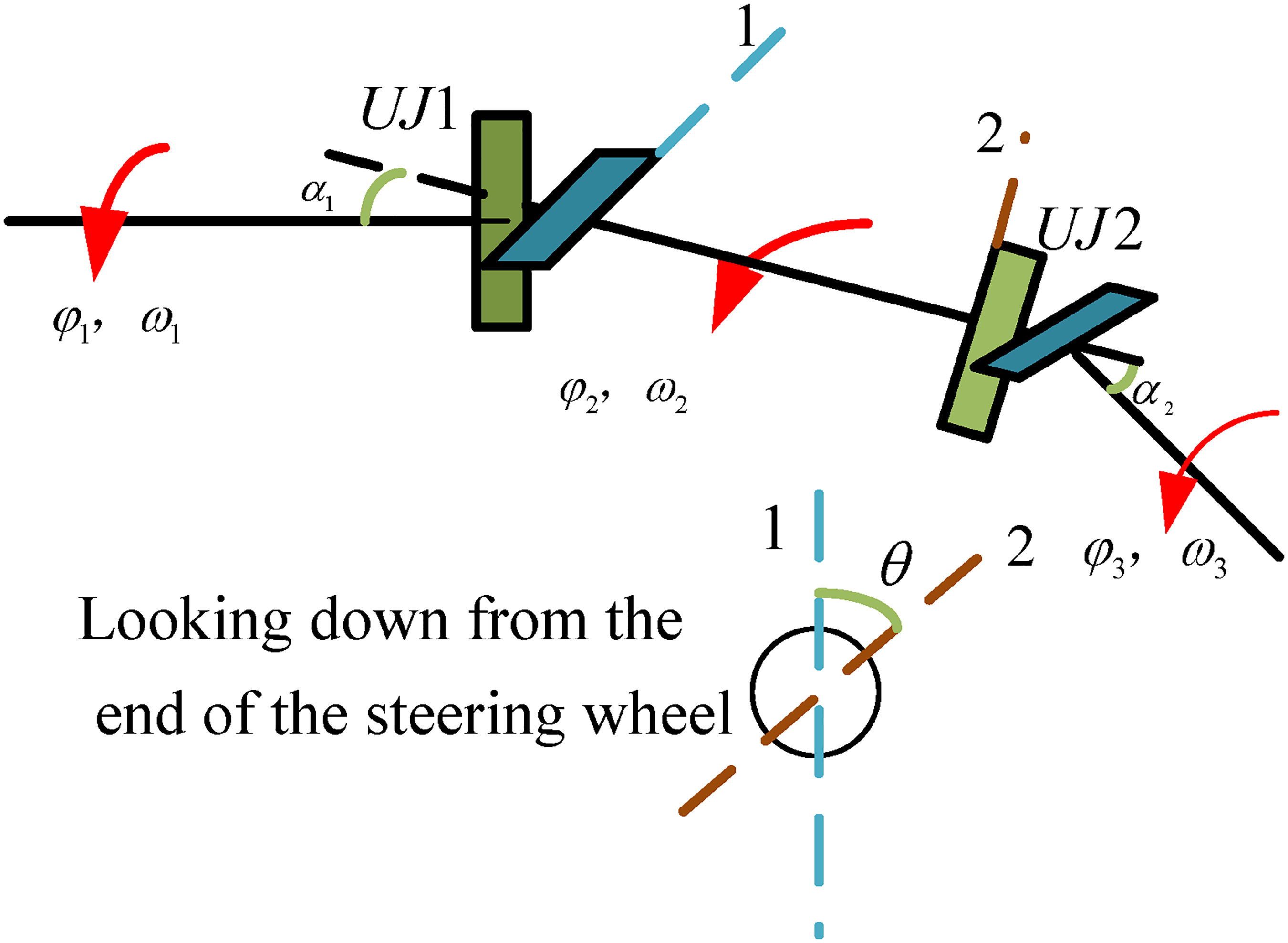
For most vehicles, the steering system is installed with universal joints. The analysis of force transmission and angle transmission in the section “The transmission of steering system” indicates that the parameters related to the spatial arrangement of universal joints and steering shaft will impact the transmission performance of steering system, as can be foreseen. Figure 3 shows the motion of the double universal joints. The following kinematic relationships can be derived:
Movement of the double universal joints.
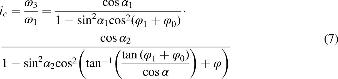
The output to input angular velocity can be obtained similarly for double universal joints:
is the initial angle of universal gearing. is the phase angle of universal gearing.
As can be known from equation (6) and equation (7), when the angular velocity of the input shaft is certain, the angular velocity of the intermediate shaft and the angular velocity of the output shaft are both periodic functions with a period of 180° of the input angle .
According to equation (8), the torque relationship between the input and output shafts can be determined:19,20
is the torque of input shaft. is the torque of output shaft .
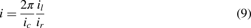
Based on the analysis presented above, it is apparent that the steering ratio i can be subdivided into three parts: the steering shaft ratio , the steering gear ratio , and the tie rod ratio , when considering the transmission in terms of the steering ratio. The mathematical expression for the i is as follows:
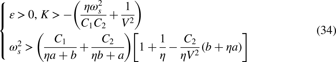
Equation (10) describes the relationship between phase angle and initial angle and transmission ratio.
Simulation test of the influence of universal gearing on steering transmission
The steering shaft ratio is the ratio of the angular velocity of the steering output shaft to that of the input shaft. As can be seen from equation (8), is influenced by the phase angle of and the initial angle of the steering shaft. In this paper, the influence of and on steering transmission will be analyzed through simulation. The values of and for the original vehicle are 0° and 60°, respectively.
Figure 4(a) shows front wheel angle in correlation to steering wheel angle with different and . Figure 4(b) shows the torque of pinion in correlation to steering wheel torque with different and . From the simulation results, it is clear that and have a significant influence on the torque transmission and angle transmission. The results obtained are in agreement with the theoretical analysis mentioned earlier.
(a) Front wheel angle relative to steering wheel angle with different and ; (b) torque of pinion relative to steering wheel torque with different and ; (c) at different ; (d) i at different ; (e) at different ; (f) i at different .
Figure 4(c) shows the in correlation to steering wheel angle with different . The curve shifts sideways with different , indicating that mainly influences the phase of . Figure 4(d) shows the i in correlation to steering wheel angle with different . As illustrated in the figure, the primary influence of on the is reflected in the phase, while its impact on the amplitude is relatively insignificant.
Figure 4(e) shows the in correlation to steering wheel angle with different . The curves show different fluctuations with different , indicating that mainly influences the amplitude of . Figure 4(f) shows the i in correlation to steering wheel angle with different . As depicted in the illustration, influences the amplitude of the i mostly and has a minor influence on the phase.
Theoretical study of vehicle handling dynamics
The dynamics of the vehicle and steering system
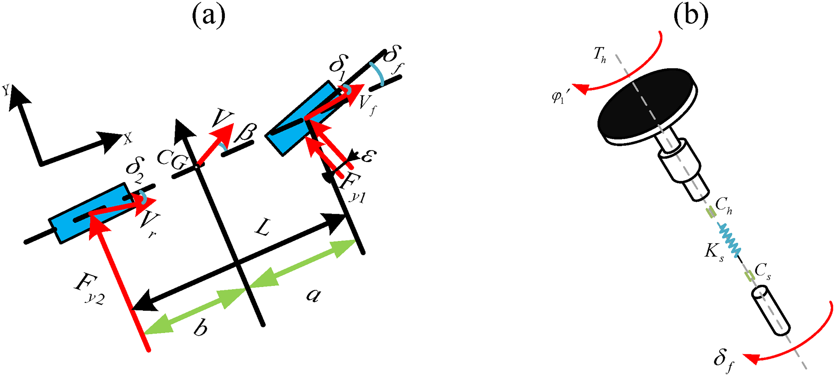
This paper focuses on the effect of the steering system on the lateral movement and yaw movement of vehicle. The 2-DOF vehicle model as shown in Figure 5(a) is used for the dynamics performance analysis of vehicle.
(a) 2-DOF vehicle model; (b) 2-DOF steering system model.
The force balance in the Y direction and the torque balance around the center of gravity can be obtained as follows if the effect of aerodynamic is not considered. In cases where the lateral acceleration of the vehicle does not exceed 0.4g (where g represents the gravitational acceleration), a linear model (, ) is used to characterize the lateral force acting on the front and rear tires. can be expressed by vehicle velocity V, side slip angle of mass center , the yaw rate r, the distances between the mass center and front and rear axes, and the front wheel angle
The differential equation of vehicle motion with 2-DOF can be presented:
denotes vehicle mass. I denotes inertia of yawing .
Section “The transmission of steering system” provides a detailed analysis of torque transfer for different components of the steering system. The conversion of the steering system's motion to the kingpin is carried out in this section to enable the analysis of its influence on the vehicle dynamics. Figure 5(b) shows the simplified model of an equivalent 2-DOF steering system.21 The steering angle is equivalent to the kingpin to obtain the equivalent steering angle . In this context, the driver's applied torque, denoted as , is considered equivalent to the kingpin. Similarly, the moment of inertia of the steering wheel, represented as , is also equated to the kingpin to obtain the equivalent moment of inertia denoted as . The moment of inertia of the steering wheel around the kingpin is represented as . Damping coefficients denoted as and are equivalent to kingpin, while represents the comprehensive stiffness of steering system.
The relationship between and , and is satisfied:
The external torque of the steering system is composed of the external torque applied by the driver and the torque around the kingpin generated by the lateral force and the combined value of the Pneumatic trail and the Mechanical trail . The primary focus of this research is the study of steering wheel rotation and the motion of front wheels as its rotate around the kingpin. Combining equation (12), the dynamic equations of the steering system can be formulated and presented:
Combined with equations (11) and (13), the vehicle dynamic equations taking into account steering system can be formulated and presented:
The influence of steering ratio on the dynamics of angle input
When the driver changes the position of the steering wheel according to a specific pattern, the equivalent steering wheel angle is no longer a state of motion variable.21 The front wheel angle can be found by for a known equivalent steering wheel angle and thus equation (14) will be meaningless. At this point, the dynamic equations the vehicle considering the steering system in combination with equations (11), (15), (16), and (17) are as follows:
When steering handling frequency is at low frequency. The moment of inertia and the damping coefficient of the steering wheel can be ignored when steering motion at low frequency, so can be obtained by from equation (15):
Then equation (18) can be written as a 2-DOF system with input and , output:
Where:
From equation (19), it can be seen that the influence produced by the steering system stiffness can be considered to be that produced by the cornering stiffness . As a result, can be regarded as the effective cornering stiffness of front wheel.
The transfer function characterizing r and side slip angle to steering angle can be obtained by equation (20). The transfer function characterizing lateral acceleration to steering input can be determined by characterizing the transfer function of yaw rate r and sideslip angle :
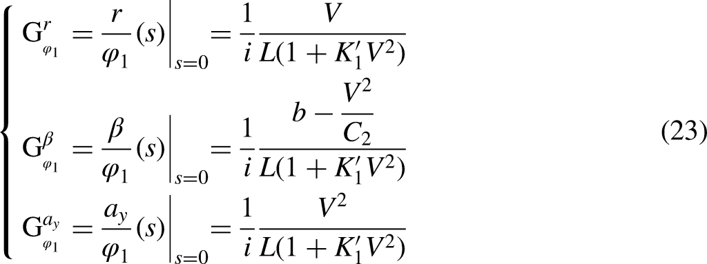
The response of vehicle to the steering angle should not be sharp or slow. The response of the vehicle is usually evaluated in terms of the yaw rate gain and the lateral acceleration gain . Yaw rate gain , lateral acceleration gain , and side angle gain can be obtained by equation (22):
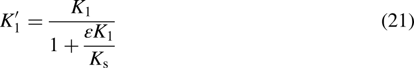
is the effective stability factor .
By inserting the value of into equation (23), the frequency characteristics of vehicle movement can be determined:
Phase frequency characteristics:
The influence of steering ratio on the dynamics of force input
The above analysis is the analysis under the condition of the driver holding the steering wheel while the vehicle handling stability also requires the vehicle to have the ability to resist interference stable driving. The steering response to the vehicle is usually evaluated by the driver releasing the steering wheel or releasing it after applying a torque to the steering wheel, that is, free control. When the vehicle is in free control, the damping coefficient can be ignored as it is very small. It can be deduced from equation (12) that the inertia with respect to the kingpin far exceeds the rotational inertia around the kingpin on account of the presence of the steering ratio i. So, can be also ignored. Combining (14) and (15), the dynamics equation for the steering system in a state of free control can be deduced as follows:
The front wheel can be calculated by equation (27):
According to equation (27), if the steering system stiffness , then the wheel turning angle . Combining equations (18), (19), (20), and (21) yields the dynamic equations of the vehicle considering steering system:
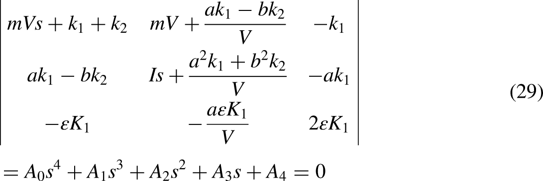
The characteristic equation can be obtained by applying the Laplace transform of equation (28):
Where:
By dividing (29) by in combination with , , and , the following equation can be obtained:
Where:
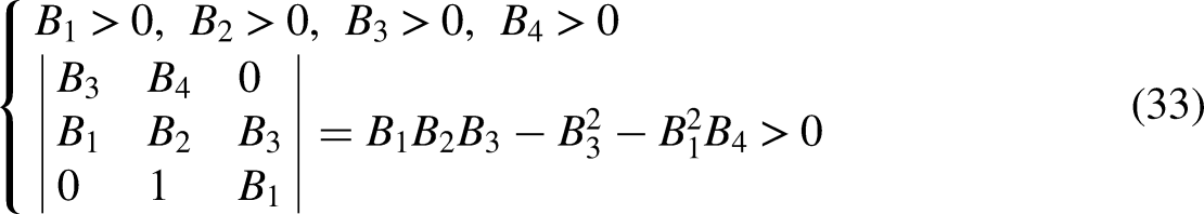
denotes natural frequency of steering system; denotes mass distribution coefficient; denotes corning stiffness of front tires; denotes corning stiffness of rear tires. The coefficients of the characteristic equation must satisfy the Rouse criterion to make the motion stable:
Stability condition can be obtained from equation (33):
It can be seen from equation (34) that the must be positive, and the vehicle must not have too strong an oversteer characteristic to ensure the vehicle remains stable under free control. If the stability of the vehicle needs to be made independent of the speed of the vehicle, let , defining at this point be . Then, it is only necessary to ensure . If this condition is not guaranteed, the critical vehicle speed can be calculated:
It is evident from equation (35) that the critical vehicle speed is positively correlated with higher values. is required to ensure that the damping is not too small within the range of actual vehicle speed. Based on the above analysis, it is clear that should be as large as possible, and from equation (36), it is clear that reducing the equivalent rotational inertia of the steering system will increase the natural frequency of the steering system. Substitute into , then . It can be further known that reducing the steering ratio i or steering wheel moment of inertia can improve the natural frequency.
Based on the aforementioned analysis, it is evident that the value of the steering ratio i will have an impact on the response of yaw rate and lateral acceleration. Under the premise of ensuring the handling portability, reducing the steering ratio can reduce the equivalent moment of inertia of the steering system effectively, thus improving the stability of the force input motion. The section “Theoretical study of vehicle handling dynamics” analyzes the influence of and on the i. This paper will conduct simulation tests to explore the influence of the changes in and on the evaluation indexes of handling stability.
Vehicle handling stability simulation
This paper develops a vehicle simulation model based on measurement data of a real vehicle. The key parameters of the simulated vehicle are presented in Table 1.
Key parameters of the simulated vehicle.
Parameter
Value
(kg)
1920.25
(m)
2.72
(N/m)
22000
(N·s/m)
1362
(m)
1.377
(m)
1.343
(N/m)
25000
(N·s/m)
1076
Swept-sine steering input simulation
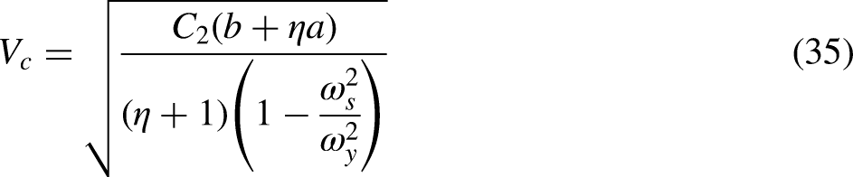
A common approach to evaluate the frequency response of a vehicle is through swept-sine steering input simulation. The following indexes are used to evaluate vehicle handling stability: (a) : the gain of the yaw rate with respect to the steering wheel angle. It characterizes the degree of steering transient response of the vehicle, with higher values indicating greater steering response. (b) : the delay time of lateral acceleration in relation to the steering wheel angle. It characterizes the lag time of steering felt by the occupant after the driver has turned the steering wheel. The smaller the value, the faster the steering response. The can be calculated according to the phase lag angle of lateral acceleration in relation to steering wheel angle :
Figure 6(a) depicts the with different . Figure 6(b) depicts the with different . From the analysis in the section “Influence of universal gearing on the transmission of steering system” and equations (22) and (23), it is clear that and influence by influencing the steering ratio i. It can also be seen from the two figures that there are significant differences in with different and .
(a) The with different ; (b) the with different ; (c) the with different ; (d) the with different ; (e) the trends of relative to and ; (f) the trends of relative to and .
Figure 6(c) depicts the with different . Figure 6(d) depicts the with different . As apparent in the two figures, the steering ratio i has a certain influence on . This is due to the fact that the i has an influence on the stiffness of the steering system. When changes, it is apparent from equations (22) and (23) that the coefficient s of the denominator and numerator of the transfer function will change, thus causing the delay time to change.
Figure 6(e) depicts the trends of with respect to and . The trends show that changes with and in a period of 180°. For the model developed in this paper, keeping constant, reaches a maximum when ( is an integer), indicating that the vehicle is less stable at this angle. reaches a minimum when , indicating that the vehicle is better stable at this angle. Keeping constant, reaches a maximum when , indicating that the vehicle is less stable at this angle. reaches a minimum when , indicating that the vehicle is better stable at this angle.
Figure 6(f) depicts the trends of with respect to and . The trends show that changes with and in a period of 180°. For the model developed in this paper, keeping constant, reaches a maximum when , indicating that the vehicle is better maneuverable at this angle.
Constant radius cornering simulation
When a vehicle is traveling in a fixed circle, the steering wheel angle needs to be adjusted to ensure that the curvature of the vehicle is unchanged as a result of the heightened lateral acceleration. The following relationship can be obtained by neglecting elasticity and clearance of steering system
is the steering wheel angle, is Ackermann's angle, is Ackermann steering wheel angle,is understeer gradient, and . The steering radius of the vehicle remains constant in constant radius cornering simulation.
The following indexes are employed to assess the handling stability of vehicle: (a) steering wheel angle gradient: the slope of with from 0.05 g to 0.4 g. The will increase with speed, so the steering wheel needs to be turned to keep the vehicle on the road radius. It demonstrates the vehicle's tendency for understeer. (b) The with at 0.05 g. It indicates the handling characteristics of the vehicle during low-speed cornering.
Figure 7(a) and (b) shows the with respect to with different and . As shown by the figures, the increased with the increase in which implies that the vehicle demonstrates a tendency for understeer. Besides, the steering ratio i differs for different and . As can be seen from equation (8), the will be influenced by the i. It is also clear from Figure 7(a) and (b) that the curve of the with respect to the is different for different and .
(a) The relative to with different ; (b) the relative to with different ; (c) the trends of with and ; (d) the trends of with and .
Figure 7(c) depicts the trends of steering wheel angle gradient () with respect to and . The trends show that changes with and in a period of 180°. Keeping constant, reaches a maximum when ( is an integer), indicating that the vehicle tends to understeer more at this angle. reaches a minimum when , indicating that the vehicle tends to oversteer more at this angle. Keeping constant, reaches a maximum when , indicating that the vehicle tends to understeer more at this angle. reaches a minimum when , indicating that the vehicle tends to oversteer more at this angle.
Figure 7(d) depicts the trends of with at 0.05 g. The trends show that changes with and in a period of 180°. Keeping constant, reaches a maximum when ( is an integer), indicating that the vehicle has good low-speed cornering performance at this angle. reaches a minimum when , indicating that the vehicle has poor low-speed cornering performance. Keeping constant, reaches a maximum when , indicating that the vehicle has good low-speed cornering performance at this angle. reaches a minimum when , indicating that the vehicle has poor low-speed cornering performance.
Cornering with steer release
From the theoretical analysis of the force input motion in the front of this paper, it can be seen that due to the change of the parameters of the universal gearing in the steering system will cause the change of the steering system ratio i, which will cause the change of the inertia of the steering wheel converted to the kingpin. Therefore, when the driver drives the vehicle in a straight line, if the driver suddenly lets go of his hand, then the vehicle will show different motion states under different structural parameters of the universal gearing. In order to evaluate the performance of the vehicle under such conditions, the cornering with steer release simulation will be carried out in this paper.
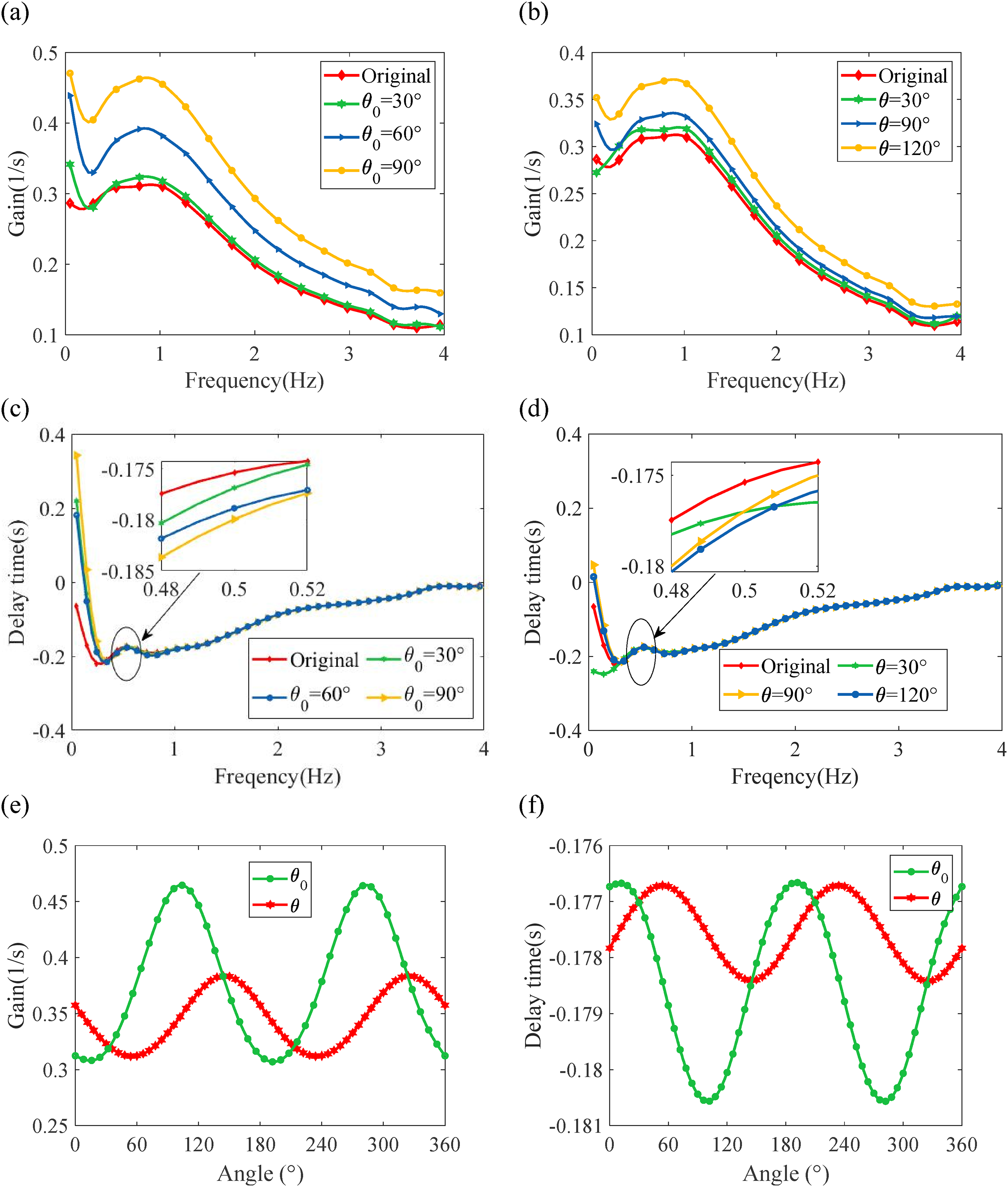
The cornering with steer release is a typical force input movement. The steering wheel angle is rotated to reach a predetermined lateral acceleration, and the force on the steering wheel is kept stable for some time, and then the hands-off stability of the vehicle is determined by measuring the change process of the yaw rate. The analysis in this paper will focus on the impact of the phase angle and initial angle on the magnitude ratio of yaw rate. The amplitude ratio is determined as the ratio between the discrepancy of the first peak value and the initial value after the hand-off, and the discrepancy between the steady-state value and the initial value. It reflects the degree of vibration decay of the vehicle after release.
Figure 8(a) presents the variations in yaw rate for different . Figure 8(b) presents the variations in yaw rate for different . Figure 8(c) presents the variations in yaw rate for different and . As can be seen from the three figures, when the steering wheel is released, the decay of the yaw rate and the steering wheel turning angle are different at different and , which is consistent with the above analysis.
(a) The yaw rate with different ; (b) the yaw rate with different ; (c) the steering wheel angle with different and ; (d) the trends of magnitude ratio of yaw rate with respect to and .
Figure 8(d) shows the trends of the magnitude ratio of yaw rate with respect to and . The trends show that the magnitude ratio changes with and in a period of 180°. Keeping constant, the magnitude ratio reaches a maximum when ( is an integer), indicating that the vibration motion decays more slowly after the release of the steering wheel at this angle. The magnitude ratio reaches a minimum when , indicating that the vibration motion decays more quickly after the release of the steering wheel at this angle. Keeping constant, the magnitude ratio reaches a maximum when , indicating that the vibration motion decays more slowly after the release of the steering wheel at this angle. The magnitude ratio reaches a minimum when , indicating that the vibration motion decays more quickly after the release of the steering wheel at this angle.
The previous analysis in this paper showed that an increase in the i leads to a larger , resulting in decreased stability during free control of the vehicle. For the angle input motion, the larger the i, the smaller the of the vehicle and the better the stability of the vehicle. It can also be seen in Figure 8(c) that the steering wheel angle is in the interval , whereas the sine-sweep input simulation has an steering wheel angle of 25°, so Figure 8(d) shows roughly the opposite trend to Figure 6(e), which also demonstrates the contradictory relationship between the angle input and the force input.
The analysis of the vehicle dynamics in the section “Theoretical study of vehicle handling dynamics” and equation (32) shows that the equivalent rotational inertia of the steering system is different with different steering ratio i, so the vehicle the natural frequencies of steering system will be different and the stability vehicle in free control will be influenced. As a result, the decay degree of the Sway of the vehicle will be different when cornering with steer release is performed on vehicles with different steering ratio. Thus, and will influence the steering ratio i and hence the stability of the cornering with steer release.
Discussion
For most vehicles, universal joints are installed in the steering system, which together with the steering shaft form the universal gearing of the steering system. Due to the existence of universal joints, the rotation speed of the steering output shaft is usually not equal to the rotation speed of the input shaft. And this unequal speed characteristic is affected by the structure of the universal gearing. On the other hand, since the driver operates the vehicle directly through the steering system, the structural parameters of the universal gearing also have an influence on the handling stability of the vehicle. This issue has not been well explored, but the rational design of the structural parameters of the universal gearing is crucial for the handling stability of the vehicle. In view of this, this paper carries out a relevant research system to illustrate the impact of the structural parameters of the universal gearing on the handling stability of the vehicle. In this paper, the influence of phase angle and initial angle of universal gearing on the steering ratio is analyzed by combining theory with simulation. In addition, the influence of the structural parameters of the universal gearing on the vehicle handling stability is also investigated. Since the evaluation of vehicle handling stability is very complex, this paper identifies three typical vehicle conditions including swept-sine steering input condition, constant radius cornering, and cornering with steer release condition to evaluate the maneuvering stability of the vehicle, and on this basis, explores the influence of the phase angle and initial angle of the universal gearing on the objective evaluation indexes of each condition.
The study shows that the evaluation indexes of all working conditions cannot be optimized under the same structural parameter of the universal gearing, and it is necessary to comprehensively consider the steering ratio curve and the objective evaluation indexes of each working condition when matching the structural parameter reasonably. The study in this paper provides a theoretical basis for improving the maneuvering stability of the vehicle by rationally matching the structural parameters of the universal gearing.
Conclusion
The influence of the phase angle and the initial angle of universal gearing on the vehicle handling stability is analyzed theoretically and verified by carrying out a series of simulation experiments. Based on the whole-vehicle model proposed in this study, the following conclusions can be deduced:
mainly influences the phase of the steering ratio i. mainly influences the magnitude of the steering ratio i.
The evaluation indexes show a period of 180° with and . In the same steering wheel angle range, the trends of the yaw rate gain for evaluating the stability of angle input with and are opposite to the trends of the magnitude ratio of yaw rate for evaluating the stability of force input with and .
The evaluation indexes may not be the optimum value under the same and . In the practical application of improving vehicle handling stability by adjusting and , the individual indexes should be considered together, which is also the future work of this study.
Footnotes
Declaration of conflicting interests
The authors declared no potential conflicts of interest with respect to the research, authorship, and/or publication of this article.
Funding
The authors disclosed receipt of the following financial support for the research, authorship, and/or publication of this article: This work was supported by the National Natural Science Foundation of China (grant number 51965026).
ORCID iD
Jin Gao
Author biographies
Jin Gao is currently an Associate Professor in Faculty of Transportation Engineering, Kunming University of Science and Technology, China. His research interests focus on vehicle system dynamics, analysis and optimization of suspension system.
Xiaoping Qi is a Master Student of Faculty of Transportation Engineering, Kunming University of science and Technology, China. His research interests are vehicle dynamics and simulation.
References
1.
EndeKVKallmeyerFNippoldC, et al.Analysis of steering system elasticities and their impact on on-centre handling. Int J Veh Des2016; 70: 211–233.
2.
Van EndeKTRKüçükayFHenzeR, et al.Vehicle and steering system dynamics in the context of on-centre handling. Int J Automotive Technol2015; 16: 751–763.
3.
PfefferPEHarrerMJohnstonDN. Interaction of vehicle and steering system regarding on-centre handling. Veh Syst Dyn2008; 46: 413–428.
4.
LiHBJiP. Analysis on vehicle on-center performance. Adv Mat Res2012; 482: 1302–1306.
5.
JoshiDKediaSMuthiahS. A Study on the Effect of Steering Input Frequency on Transient Lateral Dynamics of Four-Wheeled Passenger Vehicles. SAE Technical Paper 0148-7191, 2019. DOI: 10.4271/2019-26-00703
6.
LuJXuYHuC, et al.5-DOF dynamic model of vehicle shimmy system with clearance at universal joint in steering handling mechanism. Shock Vib2013; 20: 951–961.
7.
YanG. Analysis and optimization of torque variation in steering column assembly. In: Proceedings of the FISITA 2012 world automotive congress: volume 10: chassis systems and integration technology. Berlin, Heidelberg: Springer, 2013, pp. 57–67.
8.
KimSHChuCN. A new manual steering torque estimation model for steer-by-wire systems. Proc IMechE, Part D: J Automobile Engineering2016; 230: 993–1008.
9.
GaneshLHgPPBalaramakrishnaN. Accurate Steering System Modelling for Vehicle Handling and Steering Performance Prediction Using CAE. SAE Technical Paper 0148-7191, 2021. DOI: 10.4271/2021-26-0403
10.
CaoYCaoZGuoZ. Integrated optimization of electric power steering system based on Isight. 2016 International Conference on Advanced Mechatronic Systems (ICAMechS), November 30, 2016-December 3, 2016. Melbourne: IEEE, 2016: 389–393. DOI: 10.1109/ICAMechS.2016.7813480
11.
WangCYZhangYQZhaoWZ. Multi-objective optimization of a steering system considering steering modality. Adv Eng Softw2018; 126: 61–74.
12.
OzYOzanBUyanikE. Steering System Optimization of a Ford Heavy-Commercial Vehicle Using Kinematic & Compliance Analysis. SAE Technical Paper 0148-7191, 2012. DOI: 10.4271/2012-01-1937
13.
WadaMKamedaFSaitoY. A joystick steering control system with variable sensitivity for stable high speed driving. In: IECON 2013-39th Annual Conference of the IEEE Industrial Electronics Society, 10 November, 2013–13 November, 2013. Vienna, Austria: IEEE Computer Society,2013: 4032–4036.
14.
ZhengHMaSNaX. Design of a variable steering ratio for steer-by-wire vehicle with a joystick. Adv Mech Eng2017; 9: 1687814017730753.
15.
WeiJShiGLinY. Design of new variable steering ratio for mechanical active steering system. In: Proceedings of 2013 IEEE International Conference on Vehicular Electronics and Safety, 28 July, 2013–30 July, 2013. IEEE Computer Society: Dongguan, China, 2013: 27–30.
16.
WuXLiW. Variable steering ratio control of steer-by-wire vehicle to improve handling performance. Proc IMechE, Part D: J Automobile Engineering2020; 234: 774–778.
17.
LiFWangLLiaoC, et al.Active steering control strategy of steer-by-wire system based on variable steering ratio. 2014 IEEE Conference and Expo Transportation Electrification Asia-Pacific (ITEC Asia-Pacific), August 31, 2014-September 3, 2014. Beijing, China: IEEE, 2014: 1–5. DOI: 10.1109/ITECAP.2014.694070
18.
WuYWangLLiF. Research on variable steering ratio control strategy of steer-by-wire system. SAE Technical Paper 0148-7191, 2018. DOI: 10.4271/2018-01-1583
19.
XuSGeWZhangH. Research of the factor of non-uniform speed in double cardan joint system. J Mech Transm2014; 38: 36.
20.
MaXYuZShangD. Analyzing characters of output angular velocity of cross universal transmission shaft. Mech Sci Technol2011; 30: 1766–1770.
21.
AbeM. Vehicle handling dynamics: theory and application. 2nd ed. Oxford: Elsevier, 2015, pp.1–306.