
Abstract
A robust model-free adaptive iterative learning control (R-MFAILC) algorithm is proposed in this work to address the issue of laterally controlling an autonomous bus. First, according to the periodic repetitive working characteristics of autonomous buses, a novel dynamic linearized method used in the iterative domain is utilized, and a time-varying data model with a pseudo gradient (PG) is given. Then, the R-MFAILC controller is designed with a proposed adaptive attenuation factor. The proposed algorithm's advantage lies in the R-MFAILC controller, which solely utilizes the input and output data of the regulated entity. Moreover, the R-MFAILC controller has strong robustness and can handle the nonlinear measurement disturbances of the system. In simulations based on the Truck-Sim simulation platform, the effectiveness of the proposed algorithm is verified. A rigorous mathematical analysis is employed to demonstrate the stability and convergence of the proposed algorithm.
Keywords
Introduction
As economic development has advanced in recent years, bus operations have grown exponentially, road administration has shifted to information and automation, and bus travel has become the primary form of public transportation.1,2 Two-dimensional path planning, angular accuracy, and the effect of external disturbances on the system are all integral components of the lateral control process in autonomous bus control. Consequently, this area has become a research hub for scholars and researchers both domestically and internationally.
Gradually, classic control strategies such as sliding mode control,3,4 integrated control,5,6 model predictive control, 7 linear quadratic regulator (LQR) algorithms8,9 and shared lateral controllers 10 have been developed in response to the varying control requirements imposed on autonomous vehicles.
To boost track tracking accuracy and handle unmodeled dynamics more effectively, a novel sliding mode control method was proposed in Sun et al. and Li et al.3,4 A multi-kernel online reinforcement learning (RL) method, proposed in Liu et al., 11 was devised to achieve improved tracking performance. The research results in Li et al. 12 and Han et al. 13 all provided lateral control strategies; thus, a lateral motion control model was constructed. In the existing research presented by He et al. and Lai and Huang,5,6 the predictability of multiagent systems was studied. To bolster lateral control steadiness, the following control techniques have been formulated. Guo et al. 7 developed a nonlinear predictive control (NMPC) approach, and Yang et al. 8 and Chen et al. 9 studied a lateral control strategy based on a feedforward-predictive linear quadratic controller (LQR). A lateral control model based on a visual preview was developed in Li et al. and Jiang et al.14,15 to address the problem of lateral control of intelligent vehicles. Li et al. 10 created a shared lateral controller to address the lateral control issue. A stochastic elastic controller with uncertain growth was designed by Chang et al. 16 to handle lateral motion regulation in intelligent vehicles. A lateral control algorithm was proposed in Liu et al. 17 with the purpose of diminishing the lateral control errors induced by ACVs. With the aim of reducing the lateral control error, Tagne et al. 18 analyzed three adaptive nonlinear lateral controllers. Chen et al. 19 developed a finite-element model to estimate lateral distributions. Gao et al. 20 proposed a cloud control technique for the calculation of lateral intelligent vehicle offsets. The control methods in the above literature satisfy certain requirements, such as the high accuracy and stability of self-driving vehicles, but they do not consider situations such as external disturbances that the vehicle may be subjected to during operation.
Research considering the interference from the external environment and uncertainty of the system model during the driving process has already been conducted. Examples include a sliding mode control algorithm, 21 a robust indirect control approach, 22 a Lyapunov-based controller with a metaheuristic optimization method, 23 and an anti-disturbance algorithm 24 that addresses model uncertainty and unknown marine environmental disturbances that affect lateral vehicle motion. In addition, a novel shared control technique was suggested in Deng et al. 25 to address inverse dynamics and driving intentions. Jiang and Astolfi 26 suggested backstepping and forwarding control designs to address the underactuated issues of a class of nonlinear, underacted systems concerning nonlinear lateral dynamics control. Fan et al. and Wang et al.27,28 developed the sliding mode controller of the radial basis function neural network to address the lack of robustness of highly nonlinear vehicle models. Tang et al. 29 effectively proposed an improved artificial electric field algorithm (I-AEFA) and creatively applied it to robot path planning.
Because of the limitations of the control mechanism itself, the methods listed above are based on developing a precise model for the controlled object. In most real-world driving cases, mathematical and theoretical models of autonomous buses are difficult to construct accurately; naturally, achieving the desired control effect is challenging. For this reason, when a precise mathematical bus model is not known, the data-driven control approach exclusively considers the input and output data of the system under consideration.
When the lateral/longitudinal model of the self-driving bus is difficult to establish accurately, the proposed model-free adaptive method is used to design the lateral/longitudinal controller, which can make the bus reach the desired position and attitude quickly.
In the numerical simulation process, the usual model can achieve better results, but in actual vehicle operation, due to the vehicle hardware, weather, road conditions and other reasons, an accurate mathematical model cannot be established; at this time, the data-driven control method can be applied.
Today, a plethora of data-driven control approaches have been developed to manage these issues. These include virtual reference feedback tuning (VRFT), 30 lazy learning control (LLC), 31 iterative feedback tuning (IFT), 32 iteration learning control (ILC), 33 and model-free adaptive control (MFAC). 34
Because the MFAC method is computationally small and adaptable, MFAC is used in this article. ILC is an effective control strategy, as autonomous buses employ repeated operations, thus making it possible to effectively utilize the repeated information of the controlled system. At the same time, the influences of various disturbances on an autonomous bus during the driving process also need to be solved by an effective control scheme. Consequently, this article presents a robust model-free adaptive iterative learning control (R-MFAILC) approach for autonomous buses.
The contributions of this article are as follows.
An R-MFAILC method for bus trajectory tracking control is proposed to address the lateral tracking control problem of buses under disturbance conditions. First, the controller adopts an iterative learning controller architecture in the iterative axis, and a dynamic linearized data model with time-varying parameters named PG is created. Additionally, to enhance the system's robustness, an adaptive attenuation factor is added to the R-MFAILC controller's design. The proposed method offers a major advantage: the controller is not only able to exploit the input and output data of the regulated system but also highly resilient and can cope with the system's measurement nonlinear disturbances. Through rigorous mathematical analysis, the stability and convergence of the proposed method are proven. Simulations conducted on the Truck-Sim platform demonstrate the efficacy of the proposed method, thus verifying its adaptive learning characteristics, its capacity to take full advantage of repeated operations, and its ability to enhance trajectory tracking's control accuracy and robustness.
In the second section of this article, a dynamic lateral bus movement process is explored along with its structure. The third section develops the R-MFAILC algorithm controller. In the fourth section, the numerical simulation results obtained by the R-MFAILC algorithm on a nonlinear system are presented. In the fifth section, a co-simulation based on the Truck-Sim platform is conducted. The conclusion is presented in the sixth section.
Problem description
In robots with four-wheel mobility, buses usually feature two rear and two front wheels, with the front wheel acting as the driving wheel and the rear wheel acting as the power steering wheel. Figure 1 displays a lateral analysis of an equivalent model; disregarding the lateral sliding of tires on the ground, the impact of the inner and outer angles of the four-wheel vehicle's front wheels is equal to that of a two-wheel vehicle's front wheel angles.

A schematic representation of the front wheels with the same angle of rotation.
Figure 1 illustrates the rear wheel axis's location
Within a very short period, the bus can be approximated as moving in the direction of the body; then, the following equation is obtained. 35
The following equation describes the lateral dynamics, with the center point between the rear wheels serving as the reference point:


Introducing the iterative axis i yields:

The following nonlinear system is considered with a one-dimensional input and a one-dimensional output:

Before introducing dynamic linearization technology, system (4) is considered to satisfy the following assumptions. 36
As far as the complete derivatives of the input and the output variables in the control system are concerned, equation (4) exists and is continuous.
On the iteration axis, equation (4) is generalized to Lipschitz; that is, it satisfies:

where
For a given angle
Generally, the above assumptions are feasible in practical applications. Among them, assumption 1 indicates that the dynamic characteristics of the controlled system are constantly changing, which is a commonly used control method that has strong practicability. From an energy standpoint, the assumption implies that in the given circumstances, the system's rate of energy alteration cannot be boundless. Assumption 3 is that the given desired body angle
Figure 1 reveals that the desired body angle
R-MFAILC scheme
Linearization method for iterative domains
A memory device stores information regarding the control input and tracking errors from the previous trajectory tracking procedure under a fixed cyclical route with repetitive tasks, and a correction to the current control input is also made to enhance the current trajectory tracking cycle's control accuracy.
In the iterative domain, the dynamic linearization process for nonlinear bus dynamics systems can be summarized as follows.
For a nonlinear system, Lemma 1 states that when

where
According to the actual operation requirements of buses,

The output of a real-world system is often detrimentally impacted by measurement disturbances. Accordingly, the measured output is:


This paper presents an unknown nonlinear model with the meaning of the perturbation term
Controller design
The controller seeks the appropriate control input to obtain the vehicle control signal based on the difference between the desired body angle
The tracking error is defined as follows:


The anti-disturbance performance of attenuation factor
From (18), we know that when


Based on equation (19), the control algorithm has two steps. The stability of both algorithm stages makes it robust. In the analysis of R-MFAILC scheme, it is determined that the R-MFAILC algorithm without the attenuation factor as the first stage can stabilize the controlled system; however, due to measurement disturbance, the tracking error was not zero for
The PG vector in the control law is an unknown parameter and thus needs to be estimated. A modified projection algorithm is employed in this paper to estimate this parameter. First, the index function is defined as follows:


The parameter vector

Combining the control algorithm (19), the previously obtained PG estimation algorithm equation (17) and the resetting algorithm (22), an R-MFAILC system for bus trajectory tracking can be provided in the following form:
Considering that self-driving buses, as actual operating vehicles, are inevitably affected by traction/braking constraints, a controller design with saturation constraints is of research interest, and the input saturation constraints
Remark 1: This paper investigates the problem of a bus traveling at low speeds, in which case the lateral and longitudinal dynamic processes can be controlled separately. When the vehicle is at high speed, the coupling problem in the lateral and longitudinal directions needs to be considered.
Convergence analysis
Pseudo-order
The PG satisfies
The majority of plants comply with this requirement, which has a practical implication: the production output should rise (or fall) when the pertinent control input is augmented. Examples include control systems for water tanks and temperature.
Assume that the system complies with assumptions 1–4 and uses the R-MFAILC approach (22). When the tracking signal
The closed-loop system is internally stable.
The method used in this paper is model-free; as a model-free control method, iterative learning control is applied to solve the bus operation control opinions. Although the bus dynamics model is not completely known, the physical significance of the control inputs and outputs of the controlled object must be known. Therefore, the dynamics analysis is conducted in the Problem description section, mainly to understand the input‒output relationship of the controlled object (i.e., the unmanned bus in this paper) more clearly. The actual conditions do not necessarily operate exactly according to the established system model, that is, some of the information in Eq. (7), such as the coefficient of rolling resistance of the bus wheels and the additional ramp resistance, can be uncertain, but the relationship between the control inputs and the control outputs is certain, that is, known as analyzed in the Problem description section. Second, the general nonlinear model we built is only used to generate input and output data during the simulation process, and the model itself is not involved in the design of the controller.
Simulation and analysis
Practically, a bus generally travels along a road with curved turns when the direction changes based on the characteristics of road construction. To illustrate the efficacy of the control strategy, this paper has two sections. In the Simulation analysis of the R-MFAILC algorithm section, a nonlinear nonminimum phase system (28) is used to verify the effectiveness of the piecework attenuation factor in the R-MFAILC algorithm proposed in this paper. To verify the applicability of the R-MFAILC algorithm, Simulation analysis comparing R-MFAILC with different control algorithms section employs the lateral dynamic description system (7) suggested in the Problem description section.
Two iterative learning algorithms are utilized for comparison experiments in this paper.
The conventional MFAILC algorithm in reference
38
is:


Parameter settings of the two control methods.

The PID controller settings are as follows:
Simulation analysis of the R-MFAILC algorithm
In this section, the control effect of the R-MFAILC algorithm is examined. A setting of

R-MFAILC output curves produced with different error thresholds

R-MFAILC error curves obtained with different error thresholds
The desired trajectory can be described as follows:

The effect of the error threshold
Errors induced by the r-MFAILC algorithm with different values of

Figure 2 displays the R-MFAILC output curves obtained with varying error thresholds
Figure 3 displays the R-MFAILC error curves obtained with varying angular error thresholds 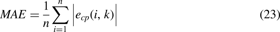
The R-MFAILC error curves obtained with various error thresholds
Table 2 reveals the error thresholds
Through the error analysis in Figures 2 and 3 and Table 2, it can also be seen that the tracking effects of the three different values are different. The error threshold value of
In order to study the influence of controller parameters on control performance, we studied the parameters η, λ and μ, as shown in Figure 4.

Comparison of the tracking effect with different controller parameters
As shown in Figure 4(a), when η is adjusted to 0.1, the frequency of iterative convergence is significantly lower than 20.
As shown in Figure 4(b) and (c), when λ is 10 and μ is 20, there is a smaller convergence error, and the number of iterations is smaller than when λ takes other parameters.
In summary, for the problems studied, the algorithm proposed in this paper still has room for improvement by setting reasonable controller parameters, and its iterative convergence speed can be lower than 20.
Simulation analysis comparing R-MFAILC with different control algorithms
This article contrasts the proposed R-MFAILC algorithm with two other ILC algorithms, PD-ILC and the traditional MFAILC algorithm, to validate its effectiveness. The controller parameters and control objectives in this section are identical to those in the Simulation analysis of the R-MFAILC algorithm section, and the resulting tracking performance and error tracking curves are depicted in Figures 5 and 6, respectively.

Comparison between the tracking effects of the R-MFAILC algorithm and those of the competing methods.

Comparison between the error effects of the R-MFAILC algorithm and those of the competing methods.
Figure 5 displays a comparison between the tracking effects of R-MFAILC, MFAILC, PD-ILC, and PID. In comparison to the other two ILC algorithms, R-MFAILC exhibits a superior tracking effect, as evidenced by the up and down oscillation of its tracking curve at approximately 450 s, while PD-ILC is unable to fully combine the necessary angle after an initial overshoot. Therefore, the piecewise attenuation factor and anti-interference ability of the proposed algorithm are significantly better than those of the comparison algorithms. The PID control method has a poor tracking effect and cannot track the desired trajectory.
Figure 6 displays the comparison between the R-MFAILC error effects and those of the MFAILC and PD-ILC algorithms, with the MAE as the error evaluation index. The R-MFAILC algorithm is faster in terms of its error convergence and lower initial error value than the other two ILC algorithms, which is particularly evident in the MFAILC algorithm after 30 iterations. Unfortunately, the final error value of MFAILC is difficult to maintain, and the error convergence rate of MFAILC is evidently behind that of R-MFAILC. In contrast, the error convergence rate of the PD-ILC algorithm is faster than that of the algorithm suggested in this paper, but its initial error is too high. PID control method in the angle of mutation moment (t = 50, 150, 250, 350, 450, and 550 s) the overshoot phenomenon, which produces in the process of actual driving serious traffic accident. The comprehensive error convergence rate and initial error value are two evaluation criteria, and the adaptability and anti-disturbance capability of the R-MFAILC algorithm are further verified.
Table 3 reveals the error calculations of the three algorithms (R-MFAILC, MFAILC, PD-ILC, PID) regarding their error effects after various numbers of iterations. According to the error statistics, R-MFAILC's error value is less than those of the other two methods, both in terms of the error convergence speed (R-MFAILC's MAE in the 6th iteration is 0.268, PID's MAE in the 6th iteration is 1.336, PD-ILC's is 0.355, and the MAE of MFAILC is 0.489) and the initial error stability value (in the 3rd iteration, the MAEs are 0.513 for the R-MFAILC algorithm, 1.285 for the PD-ILC algorithm, PID's MAE in the 6th iteration is 1.421, and 0.518 for the MFAILC algorithm). According to these two evaluation indices, the R-MFAILC algorithm has a better anti-disturbance effect and adaptive ability.
Algorithm tracking errors induced at different number of iterations.

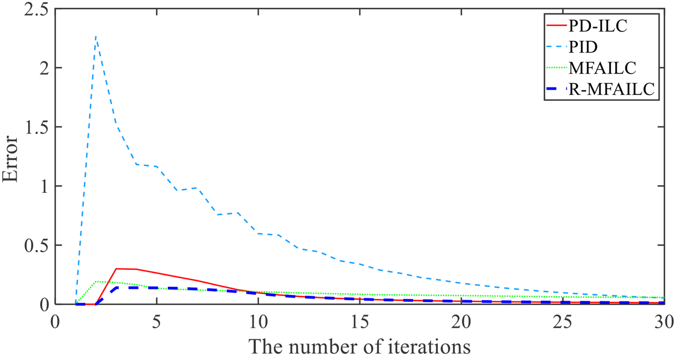
Figure 7 displays the R-MFAILC algorithm's controller inputs compared to those of the other two algorithms at varying points. It is evident that the angle change of the MFAILC exhibits varying degrees of overshoot (t = 50, 150, 350, and 450 s), whereas the PD-ILC has difficulty tracking the desired angle. Compared with those of the R-MFAILC algorithm, the control input effects of the above two ILC algorithms are poor. Without the inclusion of an iterative learning mechanism, traditional PID control methods have a poor tracking effect and cannot track the desired trajectory. Therefore, based on the above simulation results, the superior effect of the R-MFAILC algorithm in accurately controlling the input angle is demonstrated. The R-MFAILC algorithm significantly reduces body angle overshoot.

Comparison between the input effects of the R-MFAILC algorithm and those of the competing methods.
Through the error analysis in Figures 4–6 and Table 3, it can also be seen that the tracking effects of the three methods are different. Compared with the traditional ILC algorithm, the R-MFAILC algorithm is further verified in terms of its adaptability and anti-disturbance ability.
Trajectory curve tracking
This article contrasts the R-MFAILC algorithm with the other two ILC algorithms, PD-ILC and the traditional MFAILC method, to ascertain the efficacy of the proposed R-MFAILC technique in determining the actual driving trajectory curve. The control object in this section is the lateral model (3) in the Problem description section, and the specific form is as follows:


Curves of the tracking effects produced by R-MFAILC and the competing methods.

Tracking effects of the R-MFAILC algorithm and the competing methods in the X and Y dimensions.
The curves of the tracking effects produced by the R-MFAILC, MFAILC, PD-ILC, and PID algorithms are shown in Figure 8. Compared with the other two ILC algorithms, the R-MFAILC algorithm yields a better tracking effect, which is specifically reflected in the fact that the MFAILC algorithm shows up and down oscillations of the tracking curve after 400 s; the MFAILC algorithm cannot fully combine the required angle after overshooting at 100–400 s. Similarly, the PD-ILC algorithm cannot fully combine the required angle after overshooting at 100 s and displays the up and down oscillation of the tracking curve at approximately 400–550 s. After 100 s, the PID control method can not track the expected trajectory well. Therefore, the adaptation of the piecewise attenuation factor and anti-interference ability in the curve path makes the proposed approach significantly better than the comparison algorithms.
In the X and Y dimensions, Figure 9 more effectively displays the curve tracking effect of the R-MFAILC algorithm. It can be seen that the PD-ILC algorithm has difficulty tracking the required trajectory after 100 m in the X dimension, which in reality corresponds to the vehicle's difficulty in turning to a proper angle and thus deviates from the desired path. The MFAILC algorithm has a good tracking effect before 400 m in the X dimension but a poor tracking effect after 400 m. Verification of the curve path tracking performance of the R-MFAILC algorithm is thus established from the simulation results presented above. The PID control method has a poor tracking effect and cannot track the desired trajectory.
In Figure 10, the R-MFAILC error effects are compared to those of the MFAILC, PID, and PD-ILC algorithm curve path, with the MAE as the error evaluation index. The R-MFAILC algorithm's error convergence rate is faster, and its initial error value is lower than those of the other two ILC algorithms; this is especially evident in the MFAILC algorithm after 30 iterations, where the final error value is lower. The PD-ILC error curve is unsteady from the 3rd iteration to the 20th iteration, and its initial error is much greater than that of R-MFAILC. Despite the initial error value of the MFAILC algorithm being less than that of the algorithm proposed in this article, after approximately 10 iterations, the error convergence rate of the MFAILC algorithm is significantly lower than that of the R-MFAILC algorithm. And the PID control method is not satisfactory either in the initial error or in the error convergence rate. The comprehensive error convergence rate and initial error are two evaluation criteria, and the adaptability and anti-disturbance capability of the R-MFAILC algorithm for curved paths are further verified.
Comparison between the errors of R-MFAILC and the competing methods under curve trajectories.
Table 4 reveals the curve path error calculations of the four algorithms (R-MFAILC, MFAILC, PD-ILC, PID) across different numbers of iterations. The error statistics in Table 4 indicate that R-MFAILC has a lower error value than the other two methods, both in terms of its error convergence speed (in the 6th iteration, R-MFAILC's MAE is 0.232, the MAE of PD-ILC is 0.961, PID's MAE in the 6th iteration is 0.961, and the MAE of MFAILC is 0.137) and its initial error stability value (in the 3rd iteration, the MAEs are 0.300 for the R-MFAILC algorithm, PID's MAE in the 6th iteration is 1.522, and 0.193 for the MFAILC algorithm). According to these two evaluation indices, the R-MFAILC algorithm has a better anti-disturbance effect and adaptability for the curve path.
Algorithm tracking errors induced under a curved trajectory.

Figure 11 displays the controller inputs of the R-MFAILC algorithm in comparison with those of the other two algorithms at varying times. It is evident that MFAILC and PD-ILC exhibit varying levels of overshoot at 30 and 300 s of angle change. In comparison with that of the R-MFAILC algorithm, the control input effects of the other two ILC algorithms are inadequate, resulting in vehicle running jitter, which has a detrimental effect on its stability and safety. Since PID does not introduce iteration mechanism, it can not achieve complete tracking, and the tracking effect is not ideal. The R-MFAILC algorithm's superiority in controlling the input angles is evidenced by the simulation results, which demonstrate significantly reduced body angle overshoot.
Input effect curves of R-MFAILC and the competing methods.
Through the error analysis in Figures 8–11 and Table 4, it can also be seen that the tracking effects of the three methods are different. Compared with those of the traditional ILC algorithm, the adaptability and anti-disturbance ability of the R-MFAILC algorithm are further verified in the curve path.
Simulations
To further validate the practicality of the proposed technique, a co-simulation experiment is conducted in this section. The simulation environment is set as a conventional two-lane road with some degree of curvature. Moreover, the simulation model is set by referring to a BJ6105EVCA-49-type bus produced by BEIQI FOTON MOTOR Co., Ltd Moreover, a physical view of the BJ6105EVCA-49-type vehicle is shown in Figure 12.

Physical view of the BJ6105EVCA-49-type vehicle.
The corresponding specific vehicle configurations can be seen in Table 5.
BJ6105EVCA-49 bus-related data.

A co-simulation model, depicted in Figure 13 with Truck-Sim and MATLAB Simulink, is the basis of the simulation platform.

Truck-Sim- and Simulink-based co-simulation models.
Table 5 reveals the vehicle path and parameter settings shown in Figure 13, and Figure 13 illustrates the established simulation control system. Moreover, this co-simulation includes external disturbances when the vehicle runs, as outlined below (Figure 14):
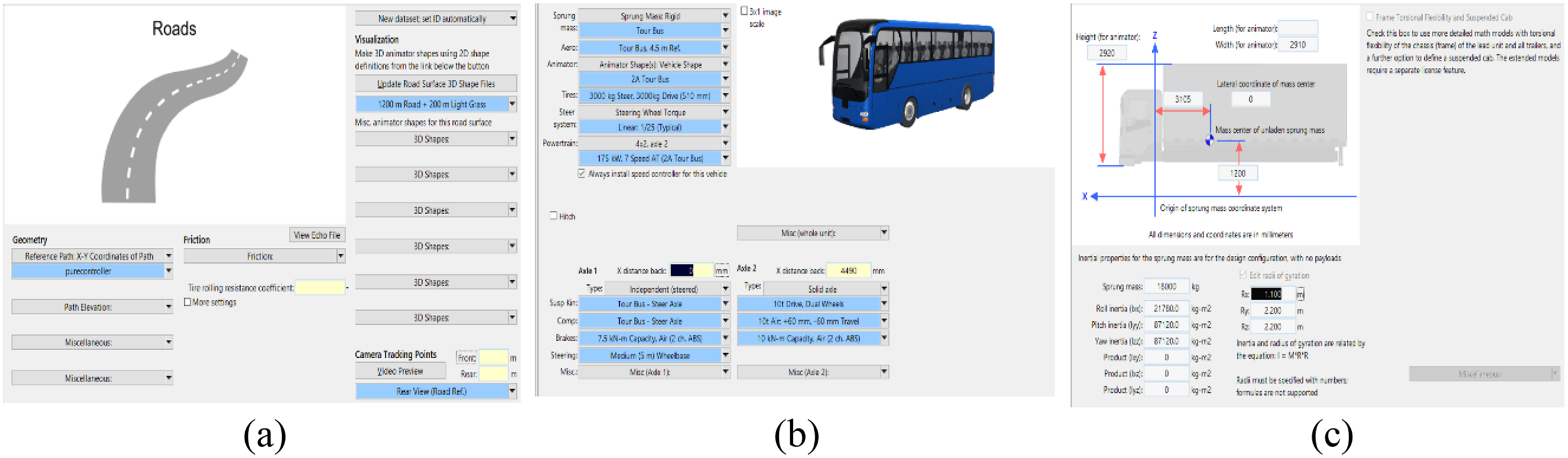
Vehicle trajectory and parameter settings. (a). The vehicle road condition data (b) are configured, and the vehicle dynamics parameters (c) are adjusted to incorporate the physical structure data of the vehicle.
Notably, the relevant parameter settings are the same as those in the Trajectory curve tracking section.
The results obtained in the lateral trajectory tracking simulation with the three control methods after 30 iterations are depicted in Figures 15–17 with the R-MFAILC control method exhibiting a certain deviation in the lateral position of the vehicle between 17 and 47 s. A certain deviation is observed in the vehicle's yaw angle in the curve range of 3–22 s. The maximum absolute value of 0.117 m for the lateral position error is allowed, and the maximum absolute error value for the yaw angle does not exceed 9.632°. In contrast, the maximum lateral and cornering errors induced under the PD-ILC algorithm are 0.166 m and 10.285°, respectively, and the maximum lateral and cornering errors induced under the MFAILC algorithm are 0.132 m and 21.771°, respectively. Compared with PD-ILC and MFAILC, R-MFAILC is more capable of fulfilling the needs of trajectory tracking. Figures 15 and 16, which display the position and cornering errors, respectively, further support the above conclusions.

Tracking images of R-MFAILC, PD-ILC and MFAILC.

Lateral position errors of R-MFAILC, PD-ILC and MFAILC.

Lateral angle errors of R-MFAILC, PD-ILC and MFAILC.
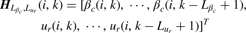
In Table 6, we present the root mean square error (RMSE) and mean square error (MSE) error evaluation indices to illustrate the controller's control effect in greater detail, as well as the lateral motion control errors:
Motion control errors.


The absolute error
Table 6 reveals that among the three control methods, the proposed control algorithm is more successful in tracking lateral positions.
Conclusion
This work introduces a novel dynamic linearization method in the iterative domain based on the periodic repetitive operating characteristics of autonomous buses to provide lateral control. First, a data model with time-varying parameters, named PG, is presented, and then an R-MFAILC controller with an adaptive attenuation factor is designed. The proposed approach has the benefit of a controller that not only takes input and output data from the controlled system but also has robustness and the capacity to manage nonlinear interference from the measuring system. To assess the efficacy of the algorithm, numerical simulations are conducted, and co-simulations are implemented on the Truck-Sim platform to validate its applicability. Through a range of exact mathematical examinations, the suggested algorithm is shown to be steady and convergent.
As a next step, we will conduct hardware-in-the-loop validation or field testing to further validate the proposed control scheme.
Footnotes
Declaration of conflicting interests
The authors declared no potential conflicts of interest with respect to the research, authorship, and/or publication of this article.
Funding
The authors disclosed receipt of the following financial support for the research, authorship, and/or publication of this article: This work was supported by the Beijing Municipal Natural Science Foundation under Grants, NorthChina University of Technology YuYou Talent Training Program, National Natural Science Foundation (NNSF) of China under Grants, R&D Program of Beijing Municipal Education Commission, Beijing Science and Technology New Star project under Grant (4212035, 4222045, 62173002, KM202310009010, KM202210009011, 20220484199).
Author biographies
Shida Liu, received the Ph.D. degree at the advanced control systems laboratory from Beijing Jiaotong University in 2017. He is currently a Associate professor of School of Automation, North China University of Technology University. His research interests include learning control, data-driven control, complex industrial process, and autonomous car.
Wei Huang received his bachelor's degree from Henan Institute of Technology, Xinxiang, China, in 2017 and is currently pursuing a master's degree from North China University of Technology Beijing, China. His current research interests include iterative learning control, adaptive control, and data loss.
Honghai Ji, received the Ph.D. degree at the advanced control systems laboratory from Beijing Jiaotong University in 2017. He is currently a Associate professor of School of Automation, North China University of Technology University. His research interests are in the field of multi-agent systems cooperative control, data-driven filtering and control, iterative learning control, and automatic train operation/road traffic control.
Li Wang, PhD supervisor, vice president of North China University of Technology, director of Beijing Key Laboratory of Intelligent Control Technology for Urban Road Traffic, Beijing Great Wall Scholar, Beijing Science and Technology Rising Star. He has presided over more than 30 projects, such as the National Natural Science Foundation of China, the National Key R&D Program, the Beijing Science and Technology Program, the Beijing Science and Technology Rising Star Program, the 2011 Scientific Research and Development Plan of the Beijing Municipal Education Commission, and the horizontal commissioned projects of enterprises, won nine provincial and ministerial science and technology awards, published 41 papers as the first author or corresponding author (23 papers retrieved by SCI/EI), and authorized 15 invention patents. He has six software copyrights and four published works. In 2017, he was rated as “Outstanding Communist Party Member of Beijing Universities”, and in 2020, he was rated as “Beijing Advanced Worker”. In 2015, the scientific research team led by him was awarded the “Annual Scientific Research and Innovation Team of the Chinese Society of Automation”. In terms of teaching and educating people, he has always adhered to front-line classroom teaching. In 2020, as the person in charge, he was approved as the “‘Control and Intelligence’ Beijing Excellent Undergraduate Education Team”, and in 2021, he was shortlisted for the first prize of Beijing Teaching Achievement Award, and his lecture on “Urban Road Traffic Control Theory and Technology” was rated as a demonstration course of ideology and politics in the postgraduate education course of Beijing universities.
Appendix
The proof is composed of four components. The PG vector's estimated boundedness must be determined first. Part 2 explains the convergence of tracking errors for the traditional MFAILC algorithm. In this paper, the convergence of tracking errors for the proposed R-MFAILC algorithm is demonstrated in Part 3, and as a conclusion, a discussion on internal stability is presented after Parts 2 and 3.
To demonstrate the primary outcome, the following lemma is established.
This leads to
where
If we choose
Note that
As
Obtaining a constant b is challenging because MFAC is designed solely based on I/O data and lacks the incorporation of model information. Selecting
Based on the previously stated lemmas, the subsequent results can be presented.
Figure A1 displays
As
Case 1
To highlight the advantages of the attenuation factors introduced by R-MFAILC, this paper first analyzes the convergence of traditional MFAILC methods.
The discrete-time SISO nonlinear system is used to attain the dependable steadiness of the MFAILC algorithm:
f (·) is an unknown nonlinear function with unknown orders of the output
For the nonlinear system (A10) that fulfills Assumptions A1–A3, then there must exist a
We will analyze the statistical properties of tracking errors to assess the influence of measurement disturbances, as they can also be used to gauge the output performance of the regulated system. The following property can be provided.
where
We now demonstrate the statistical characteristics of the tracking mistake to further validate the effectiveness of the suggested algorithm.