
Abstract
The bolted angle connections which are simple, fast, cost-effective, high quality, and no site welding have been recognized as their excellent performance. The moment-rotation behavior of both major and minor axis should be both taken into considering, however, the lack of research on minor axis limits the more comprehensive application. Five monotonic tests were carried out to investigate the influence under different parameters, and a new type connection were considered and detailed. Refined finite element models were built to validate the experimental results and to do several parametric analyses on initial rotational stiffness and plastic moment resistance, including of a presence of stiffened seat angle, angle thickness, and prying force. Furthermore, a new simplified plate method was proposed for calculating stiffness of stiffened angle and web in bending. The stiffened angle gives a significant increase at the moment-resisting capacity and the initial stiffness, the ultimate rotation of all tested specimens was beyond 0.067rad. The initial stiffness and plastic moment resistance of the joints were also controlled by the column web. The presence of the stiffener in the compression zone has the none effect on initial stiffness. The numerical analysis has captured the failure reason for weld and more attention should be paid to welding of stiffener in engineering design and practice. Adding stiffener at the top-and-seat angle joint can reduce the prying force of bolt, but it still cannot be ignored. The theoretical results were in good agreement with the experimental data and finite element results; therefore, it can be used to guide the design and selection of joints.
Keywords
Introduction
Bolted angle connections had been widely used in steel structures since the earthquake in Northridge 1 and Hyogoken-Nanbu 2 caused many severe damages in welded steel moment structure, particularly in the joints of the frame. The bolted angle connections which are simple, fast, cost-effective, high quality, and no site welding can be recognized as their excellent performance. Angle connections with different geometric dimensioning, steel assemblies, and loading conditions will lead to various moment-rotation curves in general, this difficulty resulted in avoiding this type of partial strength and semi-rigid angle connection in current engineering practice.
In the past decades, a wide range of experimental research was carried out to investigate the moment-rotation behavior, rotation ductility, failure modes, robustness in progressive collapse, and seismic performance of bolted angle connections.3–17 Therewith, the use of such connections has long been recognized by AISC (American institute of steel construction) 18 and Code for design steel structures 19 in China, it is assumed that these connections can’t maintain the initial angle between the intersecting members. Connection response is generally characterized with its moment-rotation curve, which is nonlinear for bolted angle connections. The component method has been suggested in the code specifications stated in Eurocode 3 Part 1.8 20 which enable to calculate of the initial rotation stiffness and moment resistance of the commonly used steel beam-to-column connections in the steel frame, but it only proposes that the characteristic of angle connection in bending is treated in a similar method as for equivalent T-stub in column major axis.
Angle joints subjected to static loading in major axis have constituted the most researches configuration. However, the moment behavior of beam-to-column minor axis connections should be considered in frame analysis, few studies are found accounting for the angles connected to the minor axis of beam-to-column connections. De Lima et al. 21 presents a simple method to assess the minor axis double angle connection to the column web by experiment and numerical simulation. Aydin et al. 22 investigated monotonic loaded beam-to-column connections designed within minor axis to analyse the influence of angle with and without stiffeners on the behavior of the beam-to-column connections, the deflection of column web strongly influenced the behavior of the connection in the minor axis. Citipitioglu et al. 23 employed 3D solid element to capture the real mechanical property of the TSA (top-and-seat angles) with double web angles connection in monotonic load, the numerical research had considered the contact between steel assembly and pretension force in high-strength bolts. Pirmoz et al. 14 validated the experimental work of Azizinamini and Radziminski 24 by ANSYS multi-purpose finite element simulation code. Brunesi 11 simulated the response of partially-restrained bolted beam-to-column under cyclic loads by solid element and simplified FE (finite element) models based on inelastic force-based fiber-element. Abdalla et al. 9 used the software ABAQUS to investigate the shear failure and prying force of top-and-seat angles with double web angles connections. Wang et al. 6 had used numerical simulation tool to investigate the influence of stiffener in stiffened seat angle and the stress distribution of Stiffeners.
In short, since the application of TSA connections become more widespread in frames, the moment behavior of both major and minor axis should be both taken into considering. However, there is limited research to quantify the moment-rotation characteristics of this type of connection subject to monotonic loads in the minor axis. In particular, the use of a stiffener to enhance the stiffness and moment resistance for connection purposes has the advantage of structural performance. This behavior has not been paid enough attention. This paper investigates experimentally and numerically the behavior of I-beam to I-column connection using stiffened TSA in the minor axis.
Experimental program
Test specimens and set-up
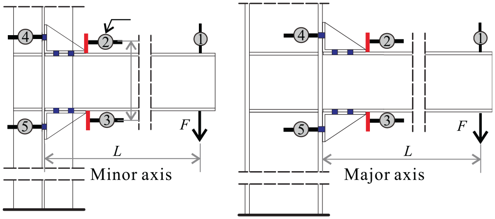
Experimental work was conducted at The State Key Laboratory of Subtropical Building Science at the South China University of Technology as shown in Figure 1. The two ends of a column were equipped with a steel assembly and loaded by a vertical hydraulic jack at the top to restrict rotation and displacement. The beam was connected to the column by a pair of un-stiffened or stiffened angle with several high-strength bolts. A lateral brace was set-up to ensure the outside plane stability of the beam during testing. One hydraulic jack was linked to the cantilever beam end to impose the displacement history for side column connection and double hydraulic jacks for interior one. Displacement control mode was selected for imposing load with a speed of 0.02 mm/s.

Test set-up.
A total of five tests were prepared for simulation and experimental test to obtain the real behavior of different types of bolted angle connections during bending, all specimens of angle (L140 × 90 × 8 with steel grade Q235), columns (H W 250 × 255 × 14 × 14 with steel grade Q345 named column 1; H M 294 × 200 × 8 × 12 with steel grade Q235 named column 2) and beams (H M 194 × 150 × 6 × 9 with steel grade Q235) were hot rolled steel. All high-strength bolts (M 16 × 70, grade 10.9, hole diameter 17.5 mm) used in the test were tightened with a manual torque wrench to a pretension force of 100 kN according to Chinese code for design steel structures. 19 The gap between the column and the beam was 2 mm. Figure 2 shows the detailed geometric configurations of the specimens.

Configuration of the five specimens.
These tests were designed to compare the effects of the following design parameters: specimens WA-1&WAS-1 was designed to investigate the effects of with or without stiffener in minor axis; specimens WA-1&WAS-2 allowed comparison of the performance between side and interior column; Specimen WAS-3 was a new type minor axis angle connection considering the thickness of column web is usually thin and difficult in bolt tightness inside the column. Thus, a plate with double transverse stiffeners was welding to the edge of the column flange; specimens WAS-1&SAS-3 enabled the effects of the different columns in major and minor axis to be examined.
Mechanical properties of specimens
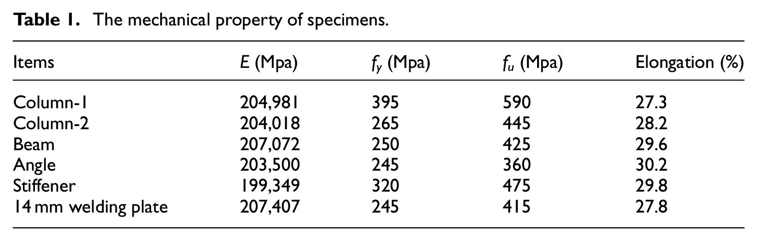
All specimens were made of the same material except column 1. Steel grade Q235 was chosen for the beam, angle, and stiffeners. The research focuses on the deformation of the angles; therefore, a strong column-1 was carefully chosen to remain undamaged for the major axis joint during the test execution. The high-strength friction-grip bolts were in steel grade 10.9. Fillet welds used between the stiffener and angle had an 8 mm leg size. The real properties of the steel were obtained employing tensile coupon tests for every kind of steel assembly. The values obtained for the yielding stress (fy), ultimate stress (fu), and Young modulus (E) are summarized in Table 1.
The mechanical property of specimens.
Instrument and test procedure
The test specimens were instrumented with four dial indicators as shown in Figure 3. The applied load (F) was obtained directly from the hydraulic jack reading from the MTS system. Transducer u1 measured the total vertical displacement of the load cell near the beam end by temposonics indicator. Transducers u2 and u3 measured the beam rotation of the connection. Transducers u4 and u5 were used for measuring the column rotation of the connection. The rotational deformation (θ) of joints which is defined as the change in angle between the center lines of the beam and column can be quantified in two different ways, according to the measurements taken.
Method one: The total displacement obtained at an endpoint u1 caused by the joint rotation (θ) and elastic deformation of the beam. Hence the joint rotation can be evaluated by expressed as

Method two: Transducers u2 and u3 measured the transverse displacement of the beam in the connection zone as shown in Figure 3.

ui is the displacement measured by transducers, where hb is the vertical distance of transducers u2 and u3, L is a horizontal distance of the load cell and the face of the column flange. In the elastic stage of the beam, rotation (θ) can be calculated by equation (1) and equation (2). Equation (3) represented the rotation of the column web, θc, in the minor axis. In this paper, the joint rotation (θ) obtained by method one and two were similar. However, method two has the limitation for a large rotation that exceeds 0.05rad due to the contact between the transducers and the beam.

Arrangement of transducers.
Finite element analysis
The numerical analysis was conducted in ABAQUS/Standard module for obtaining an efficient and precise finite element method. Both material and geometry nonlinearities were considered in the analysis. All assembly of the numerical models is presented as follows.
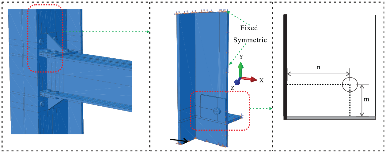
The connections consisted of a steel beam, column, angle, stiffeners, column stiffeners, and high strength bolts. The contact, pretension, friction, and real stress distribution were considered, so an 8-node linear brick incompatible mode element (C3D8I) was adopted for all parts of the specimens. To simplify the analysis process, the finite element numerical simulation takes a semi-connection, the boundary conditions were detailed in Figure 4. The structured meshing technique was used to form a proper element shape, especially for round bolts and a stiffener in angle. the total meshed model and typical parts are shown in Figure 5.

The boundary condition of the FEM models.

Finite element mesh for the solid model of the connection.
Tangent contact and normal contact were employed for the contact properties. Coulomb friction was used for tangent contact, and the friction coefficients with 0.33 were selected in terms of the tests. 6 Hard contact was used for normal contact, which simulated the deformation phenomenon between bolts and plates. The above-mentioned methods were consistent with actual situations. A Bolt Load instruction was used for imposing pretension force in a high-strength bolt in the test. The bolts of angle connection suffered both axial force and shear force. Due to complicated contact relations and high non-linear behaviors, the bolts and angle should carefully mesh for acceptable convergence. Meanwhile, weld in a stiffened angle was modeled by tie option.
The yield strength (fy) and the ultimate strength (fu) of the steel were adopted for every actual tensile coupon test result, as summarized later in Table 2. The Poisson’s ratio was assumed 0.3. An isotropic hardening rule with a von Mises yielding criterion which is suitable for simulation of metal plasticity under monotonic loading was employed to simulate plastic deformations of the steel parts. A monotonic displacement history with an increasing amplitude similar to the experimental loading protocol was incrementally imposed on the beam tip.
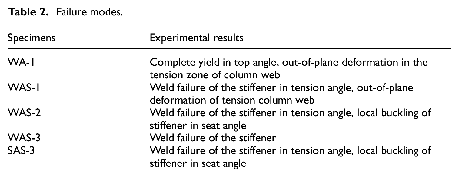
Failure modes.
For material modeling of high strength bolts, a multi-linear elastic-plastic stress-strain relationship was applied to the high-strength bolt constitutive model, which is usually applied for high strength steel, the ultimate strength (fu) is 1000 MPa and ultimate strain (εu) is 0.12 for Grade 10.9 M16 bolts, and yield strain (fy) is 900 MPa.
Experimental result
Failure modes
All the specimens exhibit high rotational performance and large deformation, the loading system was ended when loads dropped suddenly, or maximum displacement was reached to ensure the security during testing. The ultimate rotation of all tested specimens was beyond 0.067rad.
The connection was designed with stiff bolt relative to angle. Some cracks that result in a decline of loading in the fillet weld were found in all the stiffened specimens at the end of the test, Figure 6 illustrates the failure mode. Meanwhile, an obvious sign of biaxial bending in the short leg of the stiffened cleat with the painting peel was observed as highlighted in Figure 6(b). Figure 7(a) shows the un-stiffened one (WA-1) processes the highest rotation with complete yield in the cleat. In Figure 6(d) some indications of the local bucking of stiffener in the compression zone were observed after the test in specimens WAS-2 and SAS-3. If the thicker stiffener was adopted, this issue could be entirely avoided. Although the stiffener restricted the bending of the seat angle, obvious bending deformation had been found stiffened seat angle as shown in Figure 6(e). Although the column was reinforced with double transverse stiffeners, out-of-plane defection was discovered in the tension zone of the column web in specimens WA-1 and WAS-1 as illustrated in Figure 6(a). Therefore, the failure mode could be relevant to the configuration of the steel joints. The experimental results for each of the tests are explained in the following subsection. The failure modes were summarized in Table 2.

Failure modes of joints: (a) tension column web, (b) stiffened angle, (c) welding failure, (d) stiffened seat angle, and (e) local buckling.

Comparison of simulation and observed deformation patterns of the five specimens: (a) WA-1, (b) WAS-1, (c) WAS-2, (d) WAS-3, and (e) SAS-3.
Preliminary concept of M−θ curve
The behavior of moment connections is typically represented by an M−θ curve that describes the relationship between the applied moment (M) in connection and the relative rotation (θ) between the beam and column which is described indirectly in Section 2.3. The test moment (M) was computed by multiplying the force at load jack with the distance (L) between the central line of the loading jack and beam end.

Figure 8 is a typical M−θ curve obtained from tests. The following characteristics are defined: the initial stiffness (Sj.ini), the plastic moment of resistance (Mp), the ultimate moment (Mj.u), and the rotation (θj.u) corresponding to Mj.u. The initial stiffness (Sj.ini) is defined as the slope of the linear stage of the loading and unloading branches (the unloading branch is not traced in the graphs) of the M-θ curve. The plastic flexural strength (Mp) is given by the intersection between two lines6,13: one tangent to the initial stage, and the other tangent to the final stage of the M–θ curve. The first line represents the initial stiffness (Sj.ini) and the second line is on behalf of the post-limit stiffness (Spy). All of these parameters are listed in Table 3 and Figure 9.

Main parameters of the moment-rotation curve.
Main properties of M-θ curves of the monotonic test.

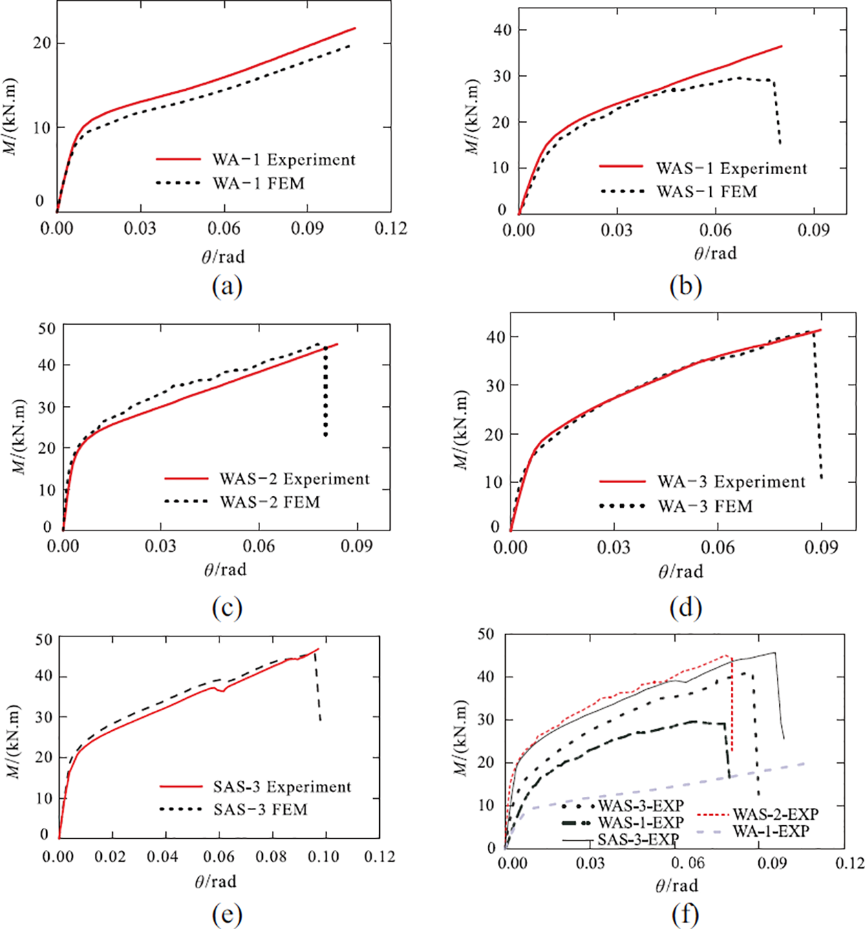
Moment-rotation curves of experiment and FE analysis: (a) WA-1, (b) WAS-1, (c) WAS-2, (d) WAS-3, (e) SAS-3, and (f) all specimens.
Analysis of tests results
Test specimens WA-1 and WAS-1
The Specimen WA-1 was an un-stiffened STA connection bolted to the column web, there were two main resources of deformation contribute to rotation of joint according to observation on the failure pattern. The first one was lateral defection that was pulled by tensile bolts in the column web, the second one was bending in an un-stiffened angle led to horizontal displacement. WAS-1 was the one with two triangle stiffeners that were welded in WA-1, obvious lateral deformation was also found in the column web. Moreover, the deformed stiffened angle showed bi-axial bending, an arc yield line was marked in Figure 6(b). The ratio of stiffness (1886/1505 = 1.25) is 1.25, 25% was increased in initial stiffness when stiffener was added, Mp was improved by 91%. Specimen WA-1 was stopped when the displacement arrived ultimate state of loading devices, but the un-stiffened angle bears large deformation with no crack, the ultimate rotation (θu) of Specimen WAS-1 was reduced by at less 0.04rad when it is compared to Specimen WA-1. Hence it can be concluded that adding stiffener in STA connection when the connections were bolted to column web is an effective way to improve Sj.ini and Mp, but ultimate rotation (θu) was decreased.
Test specimens WAS-1 and WAS-2
Specimen WAS-2 was a symmetry connection with double beams connected to the web of the interior column, there was no lateral deformation was measured due to the same displacement was imposed at the end of two beams. A relative stiff bolt was used in these joints, therefore initial rotational stiffness and plastic moment resistance depended on the stiffened TSA. Specimen WAS-1 was a joint used in the exterior column. In both tests, weld failure was initiated at the top edge of the stiffener. An increase of 52% in Mp and 237% in the initial stiffness Sj.ini in Specimen WAS-3 in comparison with the Specimen WAS-1 can be observed. Thereout, the Sj.ini and Mp of the minor axis joints were controlled by the column web in Specimen WAS-1, although the transverse stiffening ribs were added in the reverse direction.
Test specimens WAS-2 and SAS-3
TSA was bolted to column flange in most engineering practice cases because, given this, a stiffened TSA connection in major axis named SAS-3 was adopted and bolted to a relatively rigid column-1 with double transverse stiffeners. The initial stiffness was slightly decreased due to the elastic deformation of the stiffened column flange when it compares to Specimen WAS-2. The moment-rotation curves and failure modes of WAS-2 and SAS-3 were very similar, and they processed the highest Mp.
Test specimens WAS-3 and WAS-1
As shown in Figure 2, Specimen WAS-3 was a new design angle joint with a transverse stiffened rectangle plate welded to the edge of the column flange and considers the difficulties in bolts tightness work on the column web. As motioned before, the behavior of the minor one depended on the column web, the thickness of the column web is usually small. An alternative approach was proposed, a relatively thick rectangle plate welded on the edge of the column flange can add the tensile component thickness to increase stiffness and plastic resistance of joints.
Comparison between the experimental result and the numerical model
The numerical study adopted ABAQUS to simulate the experimental joints, half of Specimen WA2-2 that considered the symmetry configuration, and the computational cost was built and modeled. In Figure 9 the moment-rotation curves obtained from both the test and FE analysis were shown. To assess the accuracy of numerical simulation models, the ratio of FE simulation and experimental results are presented in Table 3, the Sj.ini and Mp are well captured by FE models, the post-yield performance of WA-1and WAS-2 is slightly different due to the nonlinear behavior of material and contact. In general speaking, the result of the test and numerical simulation models are very close.
The slippage occurred when the shear force exceeded friction force in surfaces between angle long leg and beam flange in experimental observation, as noted in test specimens SAS-3 and WAS-3, the maximum slippage (The gap between bolt and hole was 1.5 mm) result in a drop at the moment until contact is achieved between bolt and plate. In finite element analysis, the slippage was found in surfaces between tensile stiffened angle and beam flange around 40 kN.m.
According to the description of the experimental results, the tensile column web was a pivotal component, the Figure 10(c) and (d) show the lateral displacement and Mises stress distribution of column web of WAS-1 under ultimate state, so yield and deformation mechanism was obtained.
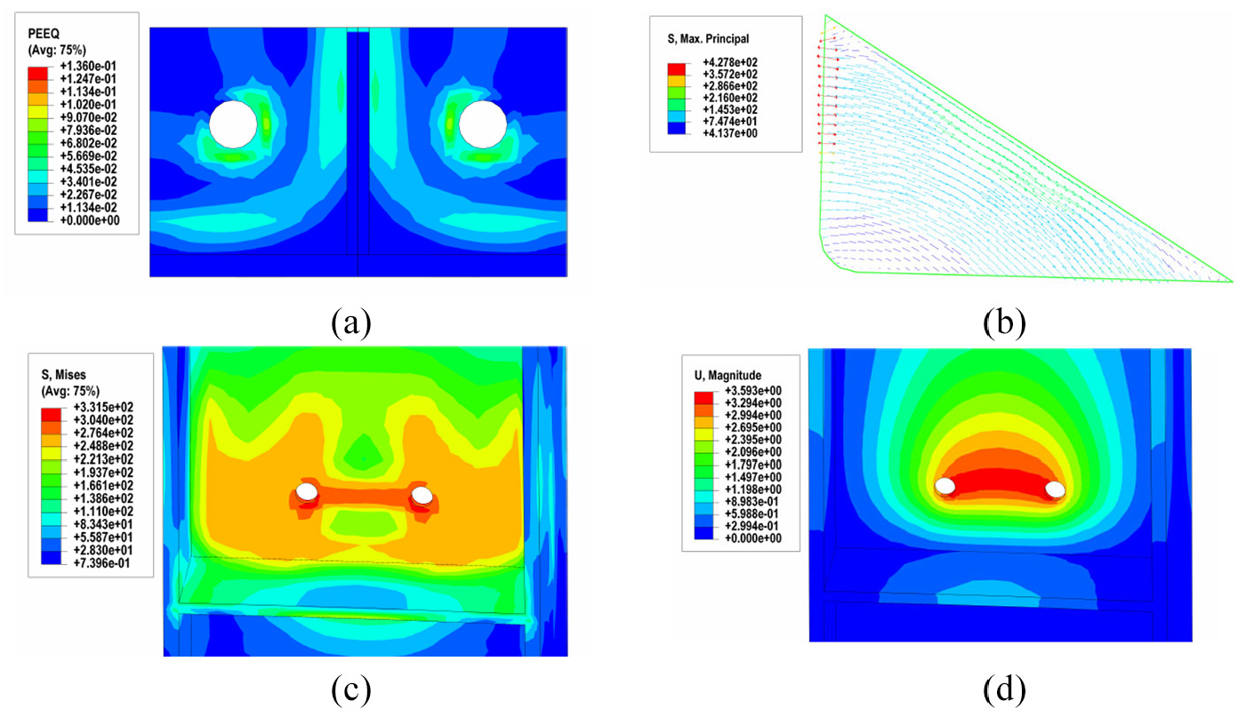
Numerical results of the connecting parts: (a) the value of PEEQ in stiffened top angle, (b) distribution of principal stress in stiffener, (c) distribution of mises stress in tensile column web, and (d) distribution of out plane displacement in tensile column web.
In FE models, top angle and column web of minor axis suffered the highest deformation among the other steel parts. Figure 10(a) shows the PEEQ (equivalent plastic strain) in a stiffened angle, a vertical and a horizon plastic line from around the bolt hole due to the strong constraint by high-strength bolt, another two plastic lines that develop along the fillet and weld are more obvious. This phenomenon means that the stiffener and long leg of angle show a stronger constraint in comparison with the bolt. The stiffened angle deformed as a 1/4 simple supported plate under concentrate load.
Adding stiffeners in angle can change the loading transmit path, the shear force was more inclined to transfer from the stiffener, the principal stress distribution is illustrated in Figure 10(b) the maximum principal stress is marked by a red line, upper weld edge of the stiffener is suffered about 427.8 MPa that is beyond the ultimate capacity of the weld, therefore the numerical simulation has captured the failure reason of weld and more attention should be paid to welding of stiffener in engineering design and practice.
Parameter studies
A parameter study was performed based on numerical analysis to get a deep investigation into the behavior of the connection and identify some key factors that had a great influence on its performance. The studied parameters contained the different pretension levels, the thickness of TSA connections, and the prying force.
Role of stiffened seat angle
To assess the influence of stiffened seat angle on initial stiffness and plastic moment resistance, Specimen WAS-2 which eliminates the influence of the column was selected to carry out parameter study. The difference between the six models lies in the arrangement of stiffener base on Specimen WAS-2. Details and results of the models were listed in Table 4.
Results of the numerical models.
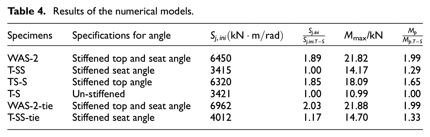
According to the comparison between specimens TS-SS and TS-S, S-T, and S-TS, the initial stiffness (Sj.ini) were not affected by adding stiffener in seat angle, but stiffened seat angle can improve plastic moment resistance (Mp). To explain this phenomenon, specimens TS-SS-tie and T-SS-tie were built and modeled that Tie constraint was used in the surfaces between seat angle flange leg and beam flange, a strong constraint as weld was established similar to the situation of stiffened extended end-plate connection, Under these circumstances, Sj.ini increased, meanwhile Mp was the same as the none tie one as shown in Table 4. It means that the bolt can’t completely restrict the opening of the interfaces at initial loading, therefore the initial rotation center is around the interface as shown in Figure 11, as the load increased, the stiffener stared to restrict the bending of seat angle, this additional effect increases the lever arm between tension forces and compression forces when the connection achieves the plastic moment.

Rotation in stiffened seat angle in numerical simulation.
Angle thickness
Four different thickness was select to apply in Specimen SAS-3, the other parameter remains unchanged, the moment-rotation curves are shown in Figure 12 and result of initial rotational stiffness are summarized in Table 5 according to finite element analysis. Slippage is captured in the graph, the first slippage occurred at beam flange, the second one was found in a short angle leg. The initial stiffness and resistance of the joints increase with the increase of the thickness, but the amount of increase is not obvious when the thicker angle was selected. For in comparison to stiffened and un-stiffened one with the increase of angle thickness, adding stiffeners in angle was a more effective way to improve Sj.ini comparing to apply a thicker angle.
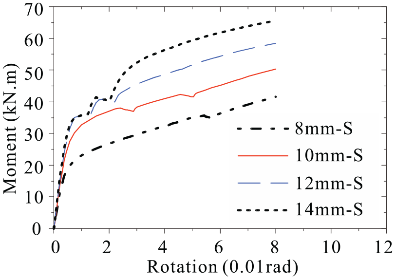
Moment-rotation curves with different angle thickness.
Initial rotational stiffness of stiffened or un-stiffened angle connections under different level pretension force with different thickness (kN.m/rad).

Prying force with or without stiffener
Tension bolts connecting an angle or T–stub may experience forces greater than the externally applied loads due to the deformations of the connected leg which acts like a lever using the tip of the leg as a fulcrum. The reaction at the tip of the leg adds additional force to the bolt. This phenomenon is known as prying. It is hard to identify the prying from the contact force due to pretension at initial loading. Three different level pretension has been installed in bolts, as illustrated in Figure 13, the pretension seems to have no effect on the prying force at the ultimate state. This phenomenon can be explained that as with the increase of load, the effect of the pretension force (CF as shown in Figure 14) will slowly disappear with the opening of the bolted plates.

The prying force with different pretension level.

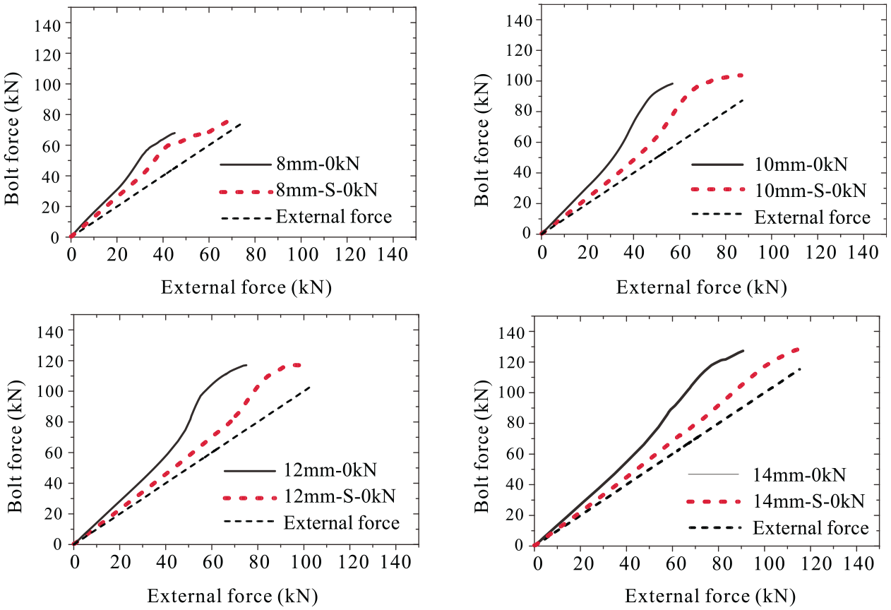
Prying force with P0 = 0 kN.
o obtain the prying force (Q = B−Fe) of the whole process through simplified analysis, none pretension bolts were used in simulation as shown in Figure 14, Prying force was increased as the external force in the bolt, then a maximum value achieved when the plastic of angle developed, later prying force decreased as the further opening of the plate increases with the stronger geometric deformation. Figure 15 shows a comparison of the prying force between stiffened and un-stiffened types with different thicknesses. According to the simulation results, the prying force declined when stiffener was welded in angles especially when the thickness increases, but it still can’t be ignored in bolt design.
Comparison of the prying force between stiffened and un-stiffened type.
As illustrated in Figures 16 and 17, the bolt force with initial pretension force equal to 80 kN dropped as the external force increased in 8 mm stiffened angle model, but for the model of pretension equal to 50 kN, the bolt force increased during the whole loading process. It can be concluded that when the ultimate tensile resistance of the stiffened angle is less than the pretension force provided by the bolt as required, the total bolt force would drop during the external force imposed, in this case, the prying force can be ignored.

A prying force with different thicknesses.

Bolt force with different thickness.
Initial rotation stiffness
General
The test results revealed that the tensive stiffened angle and column web were the main source of deformation, therefore, the initial rotation stiffness was controlled by these two key components and can be calculated by the component method suggested in Eurocode 3 Part1.8. 20 However, the stiffened angle and web were not included. Although there are studies in un-stiffened type by beam models, as illustrated in numerical simulation, the stiffened one behaved as a plate model.
The stiffness of stiffened angle in bending
As illustrated in Figure 18, to simplify the analysis process and to get the individual stiffness of stiffened angle, a half-angle stub that considers symmetric existing in the whole model was adopted in the parameter study. The bottom of the sub-model was fixed, and the bolts were preloaded, a small displacement loading as observed in Figure 19 was imposed on the tip of the connecting plate. The plate stiffness was strongly influenced by m and n, a useful dimensionless parameter β is defined as:

According to plate theory, 25 the deformation of the rectangular plate subjected to a concentrated load is represented by the following formula:

Where ω is the deflection in plate and D is the flexural stiffness of the plate can be defined as:

E was the value for Young modulus and the Poisson coefficient (ν) employed in parameter study was dependent on the experimental results.

The finite element study can get the value of the tensive stiffness (K) in an elastic state. The coefficient (η) depended on the angle thickness (t) and coefficient (β). The parameters considered have been adopted as follows: t = (8,10,12) mm; m = (37,47,57) mm; n = (31,41,51,61) mm. The parameters which had a greater impact on component stiffness can be selected by the software of MATLAB to fit a curve relating to confident bounds of 95% and represented by equations (9)–(11).


Simplified procedure for evaluating stiffened angle in bending.
Simplified procedure for evaluating stiffened column web in bending.
The stiffness of the stiffened column web in bending
As mentioned before, bolt pretension affected the initial stiffness, in the simplified FE models, the preloaded bolt and top angle leg bolted to column web were retained (Figure 19). A lateral displacement was imposed at the bolt head, the half-height of the column web was built considering the symmetric boundary condition. The finite element study can get the value of the tensile stiffness (K) in an elastic state. A similar plate theory was used as a stiffened angle. The coefficient η was dependent on the angle thickness (t) and coefficient (β). The parameters considered have been adopted as follows: t = (8,10,12) mm; m = (40,50,65) mm; n = (70,80,90,105) mm. Figure 20 shows the linear relationship between β and η with different angle thickness, curves fitting was carried out by MATLAB, the following curves provided with confident bounds of 98% and represented by equations (12)–(14).


Relationship between β and η with different thickness of top angle.
Assessment of initial rotational stiffness by component method
The stiffness of the spring element representing the joint components is evaluated according to the relationships described in the following section. Regarding the components affecting the top angle in the tensile beam, as shown in Figures 21 and 22. In particular, the main sources of deformation, that is, the stiffened top angle in bending (stab), the bolt in tension (bt), the stiffened column flange in tension (cfb) for major axis, the stiffened column web in bending (cwb) for minor axis, but they don’t locate in the same level. Therefore, the equivalent stiffness of the first bolt row must account for the need to move the contribution of these components to the level of mid-thickness of the top angle leg adjacent to the beam flange. For this purpose, the stiffness of these two components is modified using the following relationships.


Where K is the stiffness of the springs acting at the first bolt row level, as discussed in Section 5.1, the contribution of stiffened angle in initial rotation stiffness can be ignored, the mid-thickness of seat angle leg bolted to beam flange can be defined as the compression center. ha is the distance between the mid-thickness of the stiffened angle leg connected to the beam flange and the middle thickness of the stiffened top angle leg adjacent to the beam flange. The distance between the center of the first bolt row and compression center is defined as hbo. The modified individual equivalent stiffness in the same row can be obtained by equations (15)–(17).

Procedure for evaluating the initial rotational stiffness for joints in the major axis.
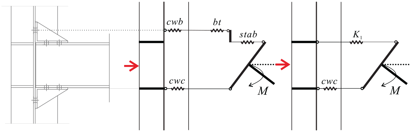
Procedure for evaluating the initial rotational stiffness for joints in the minor axis.
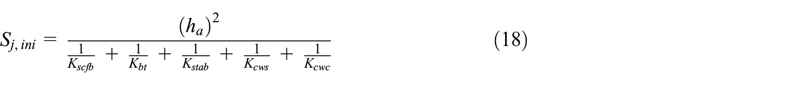
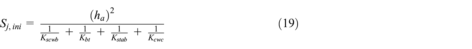
Finally, the contribution of all components is obtained by combining the stiffness of these components in a series connection. The rotational stiffness of the joints is obtained utilizing the following equations (18) and (19) corresponding to the major and minor axis.
The stiffnesses of stiffened column web in compression (cwc) and column in shear (cws) are acquired according to EC3 20 and the stiffness of preloaded bolt references. 16 In Table 6, four finite element models were developed with various thicknesses, SAS-3-a10 means the thickness of the stiffened angle is 10 mm; WAS-1-w10 means that 10 mm column web is adopted in this model. Finally, the comparison between the predicted initial rotational stiffness (predicted) of the suggested approach and the stiffness obtained from experimental results (SExp) or finite element analysis (SFE) is listed in Table 6. The coefficient of variation and the average value show the accuracy of the proposed modified component method in comparison with the FE models and experimental date.
Comparison between the theoretical stiffness results and FE data (kN.m/rad).

Conclusion
In this article, five angle joints were tested by the monotonic load, stiffened top and seat angle connections adjacent to the column web, column flange, and welding plate were investigated. The behavior of critical parts of the joints, such as stiffened angle, column web, and compression stiffened angle was studied, and failure modes of these stiffened angle connections were present. Numerical simulation validation in the same connection of experiments was conducted. The following conclusion can be obtained:
The stiffened angle gives a significant increase at the moment-resisting capacity and the initial stiffness but leads to a reduction of the connection ductility. However, the ultimate rotations obtained for the beam-to-column connection are high enough to allow the plastic analysis of the structures.
For the stiffened angle connections adjacent to column web in minor axis, the failure mode of the stiffened angle joints was caused by the fracture of the weld at the upper edge of the angle and the stiffener. There was still a large deformation in the column web when it was directly connected by angles, although the transverse stiffening ribs are added in a reverse direction. The initial stiffness and plastic moment resistance of the joints were also controlled by the column web.
A new type of stiffened angle connection connected to the welding plate in minor axis was proposed, thicker welding plates were selected therefore the deformation in the column web was avoided, besides, the rigidity and strength of the joint were increased.
On one hand, the presence of the stiffener in the compression zone has the none effect on initial stiffness due to the weak constraint provided by bolts at initial loading, the rotation center located at a middle thickness of stiffened seat angle long leg. On the other hand, the stiffened seat angle can significantly improve the plastic moment resistance by lowering of the position of the compression force in the connection from the middle thickness of stiffened seat angle long leg to the centroid of the stiffener in the compression zone, as the further bending of the stiffened seat angle was constraint by stiffener.
Adding stiffener at the top-and-seat angle joint can reduce the prying force of bolt, but it still can’t be ignored. It was worth noting that if the ultimate tensile resistance of the angle was less than the pretension force as required, the total bolt force would decrease when the external load applied, in this case, the total bolt force will not exceed the initial pretension force, and therefore the prying force can be neglected.
Two new simplified plate models were suggested to calculate the stiffness of stiffened angle and stiffened column web in bending, these new components were assembled in the modified component method considering the compression center and bolt row location. The theoretical results were in good agreement with the experimental data and FE results.
Footnotes
Appendix
Declaration of conflicting interests
The author(s) declared no potential conflicts of interest with respect to the research, authorship, and/or publication of this article.
Funding
The author(s) disclosed receipt of the following financial support for the research, authorship, and/or publication of this article: This study was supported by National Natural Science Foundation of China (Grant No. 51638009;51778241;51708226;51978279), the Fundamental Research Funds for the Central Universities (Grant No. 2019MS121; 2019PY20; 2019ZD47), and Guangdong Basic and Applied Basic Research Foundation (2020A1515011307)
Data availability
All data generated or analyzed during this study are included in this article.