
Abstract
To investigate the real physical mechanism of rock fragmentation subjected to water jet under in-situ stress condition, a numerical model based on the SPH algorithm was established using the rate-dependent constitutive model to simulate the rock-breaking process. First, the damage evolution law of rock impacted by high-pressure water jet under in-situ stress conditions was studied by analyzing the distribution characteristics of the damage field in the dynamic process of water jet impinging. The results showed that the damage field, widths of surface damage, maximum widths of damage and mean depths of damage of rock decreased with the increase of in-situ stress, indicating that the existence of initial in-situ stress had a strong inhibitory effect on rock fragmentation. The attenuation of the maximum widths of damage could be divided into two stages. The mean depths of damage of rock played a leading role in the number of damage elements. Furthermore, on this basis, the real physical mechanism of rock fragmentation subjected to water jet under in-situ stress condition was revealed by analyzing the stress states and damage history variables of the particles in the selected five typical regions. The study showed that the failure type of the upper rock elements in the crushing zone was brittle failure caused by a combination of compressive stress and shear stress with or without in-situ stress. However, the failure mechanisms of rock elements in crack zone were completely different with or without in-situ stress. In the absence of in-situ stress, the failure type of rock impacted by water jet was the coexistence of damage caused by compressive-shear stress and tensile stress, while in the presence of in-situ stress, the failure type of rock impacted by water jet was mainly the damage caused by compressive-shear stress.
Highlights
The damage evolution law of rock impacted by high-pressure water jet under high in-situ stress condition is studied
Rock-breaking efficiency of high-pressure water jet is significantly impaired under the condition of in-situ stress.
The mechanism of rock fragmentation subjected to water jet under high in-situ stress condition is revealed.
The failure mechanisms of rock elements in crack zone are completely different with or without in-situ stress
Introduction
With the rapid progress of society, the demand for natural resources is increasingly urgent, and deep well mining is an inevitable trend in the development of mining industry. The exploitation of inner-earth resources has become an important direction for the future development of science and technology in the world. 1 For deep underground engineering, the working environment and rock breakage mechanism are different from those of shallow engineering, and the rock mass to be broken is usually in a state of high in-situ stress. Research shows that among many new rock-breaking methods, the most potentially efficient and easy-to-implement rock-breaking method is the high-pressure water jet rock-breaking technology, which has great potential for development and research value. 2 In recent decades, high-pressure water jet rock-breaking technology has developed rapidly and has been widely used in underground excavation, petroleum engineering applications, civil construction, and coal mining, etc.3–7 It will be of great engineering and scientific significance to study the evolution law and failure mechanism of damage of rock impacted by high-pressure water jet under in-situ stress condition for accelerating the application of water jet rock breaking in deep engineering. In addition, as the mechanism of rock fragmentation under high in-situ stress is revealed, it will promote the efficient fragmentation of deep rock mass, which is of great value to the highly efficient exploitation of deep resources of the earth. 8
Many scholars have carried out extensive research on rock breakage mechanism and performance of high pressure water jet, and achieved certain results. Field 9 elaborated on the theory of liquid impingement, indicating that liquid impingement is divided into an initial liquid compression phase to form water hammer pressure and a liquid incompressible phase. Momber 10 studied the deformation and breakage of four rock materials and two concrete materials at a liquid impulse velocity of 900 m/s. The results showed that the brittle material damage was a damage-free central region surrounded by discontinuous microcracks, and the plastic material damage was plastic flow cracks, and an elastic-plastic transition criterion was derived. The damage mode of sandstone impacted by high-pressure water jet was studied by Lu et al., 11 and the results demonstrated that there were three different damage modes of sandstone corresponding to different jet velocities. Liu et al. 12 investigated rock-crushing efficiency via numerical simulation using JHC constitutive based on FEM combined with SPH and found that rock-crushing efficiency increased linearly with the velocity of water jet. Xue et al. 13 developed a numerical model to study the propagation of stress waves in rocks using the SPH algorithm. The results indicated that the influence range of the stress wave decreased with the increase in rock strength. Jiang et al. 14 utilized FEA in combination with SPH to simulate rock fragmentation under the impact of pulsed water jets. The results indicated that the failure of the rock-crushing zone was mainly caused by plastic behavior; however, However, the failure pattern of crack growth was brittle failure. Junkar et al. and Kumar et al. introduced the application of an elasto-plastic model-based FEA to describe the erosion behavior of materials in abrasive water jet machining.15,16
In recent years, there have been many new developments in SPH applications in rock fragmentation and rock dynamic fractures. A penalty-based contact treatment in SPH along with variable particle resolutions were adopted to simulate the fracture of granite under blast. 17 The findings indicated that the developed SPH method can be used to qualitatively and quantitatively predict the blast-induced fractures and was suitable for accurate modelling of rock under blast. Jayasinghe et al. 18 used a three-dimensional coupled SPH and FEM model to investigate the extent of blast-induced rock damage zone and fracture patterns. The results demonstrated that high in-situ stresses also have a significant effect on the extension of blast-induced fractures and the patterns of fracture networks. Yang et al. 19 adopted a coupled SPH-FEM simulation method to numerically investigate the effects of in-situ stress on blast-induced rock fracture and seismic wave radiation. The results revealed that with the increase of in-situ stress level, the size of the fractured zone was significantly reduced, and more explosion energy was transformed into seismic energy. Some scholars20–22 proposed a few numerical simulation methods based on meshless smooth particle hydrodynamics (SPH) to simulate the failure of brittle heterogeneous materials by tracking microscopic crack growth and macroscopic mechanical behavior. The research results showed that the developed SPH program can well describe the failure evolution process of cracks and large-deformation debris. Gharehdash et al. 23 developed a dual-support smoothed particle hydrodynamics (DS-SPH) method developed to quantify explosion-generated crack densities within granitic rock masses in field-scale computational domains. Mu et al.24,25 captured the brittle fracture characteristics of materials by improving the kernel function of the SPH method for simulating crack extension in brittle fracture of rock materials.
With the progress of the numerical calculation, some high-quality material constitutive equations, such as J–H–C (Johnson–Holmquist–Concrete)12,26 and JH2 (Johnson–Holmquist II),27,28 were used to characterize the mechanical performance of rock. Certain representative parameters, such as the shear stress and principal stress, were selected for the analysis, and the propagation law of stress wave in rock under water jet impinging and failure response of coal was investigated. 29 In this phase, researchers payed attention not only to the stress state of rock but also to the damage distribution and failure mechanism. They explained the mechanism of rock breakage by exploring the variation of different parameters, which is the prevailing analytical method.14,30,31 The fluid-solid coupling approach with the four main factors of 3D in-situ stress, water jet velocity, pore pressure, and fluid column pressure was developed and calculated using the finite element method and the finite volume method by Li et al. 32 The results showed that the maximum principal stress of the bottom-hole was directly proportional to the bottom-hole differential pressure. Xue et al. 33 established numerical models based on the coupled ALE-FEM method to study the fracture mechanisms of coal under the impact of two kinds of jets. The findings showed that the erosion energy of the abrasive jet was more centralized than that of the water jet, causing a smaller distribution range of the damage field in the coal.
However, due to numerous influencing factors, complex mechanism of action and the opacity of rocks, the mechanism of rock fragmentation by water jet has not been fully revealed yet. Moreover, as the exploitation of energy and other resources gradually moves to the deep, the influence of in-situ stress on rock breaking characteristics cannot be ignored. At present, there are few studies on the damage evolution law and rock breaking mechanism of high-pressure water jet impacting rock under in-situ stress conditions, which has restricted the development of rock fragmentation theory and technology by water jet to a certain extent. The development of computer technology makes it possible to study the evolution law and failure mechanism of damage of rock impacted by high-pressure water jet under in-situ stress condition by numerical method. The numerical means has been used to successfully simulate various complex physical processes in the field of geotechnical engineering and has evolved into an essential tool for the discipline. In this paper, based on the SPH algorithm, a numerical model was established using the rate-dependent constitutive model, and the damage evolution law of rock impacted by high-pressure water jet under in-situ stress conditions was studied by analyzing the distribution characteristics of the damage field in the dynamic process of water jet impinging. In addition, on this basis, the real physical mechanism of rock fragmentation subjected to water jets under in-situ stress condition was revealed by analyzing the stress state and damage history variables of the particles in the selected typical regions.
Methodology
Theory of SPH
SPH is a meshless Lagrangian algorithm, which was originally introduced by Lucy, 34 Gingold, etc. 35 to solve astrophysical problems in three-dimensional space. The traditional Lagrangian element may have serious distortion when dealing with large deformation problems, which makes it difficult to solve numerically. The SPH (Smooth Particle Hydrodynamics) method effectively solves the problem by representing continuous matter as a set of discrete particles with movable velocities. The particle obeys the conservation theorem of mass, momentum, and energy, and is solved in combination with the constitutive equation of material, so as to obtain the motion law of matter. It has been widely used to solve extreme deformation and failure types such as explosion simulation,36,37 high-speed collision,38,39 penetration calculation,23,39,40 and brittle fracture.24,41
Unlike the finite element method, a kernel approximation is used in SPH based on randomly distributed interpolation points, and the points are neighbors to calculate spatial derivatives. Considering a problem domain Ω discretized by a set of particles by collection of particles, and assuming kernel function W has a compact supporting domain with a radius of h. The approximation f


The equations of conservation governing the evolution of mechanical variables can be expressed as follows:
Conservation of mass:

Conservation of momentum:

Conservation of energy:
Where ζ is the pressure;
Model for the water jet
LS-DYNA is a well-known explicit dynamic simulation software that can effectively simulate the response of materials to short periods of severe loading. In the calculation, MAT_NULL is chosen to characterize the water because its shear stiffness is zero, and the EOS_GRUNEISEN equation of state, given in equation (6), is used to describe the performance of water because of its pressure response.
13

μs and μp can be related by the following formula

Material parameters for water jet.
HJC constitutive model for rock material
Yield strength model
In order to better describe the nonlinear deformation, damage, and failure characteristics of rock under the impact of high- velocity water jet, JHC
44
constitutive model is introduced in this study, which is suitable for characterizing the mechanical behavior of rock.30,45 The equivalent strength is expressed as a function of the pressure, strain rate, and damage. The pressure is expressed as a function of the volumetric strain and includes the effect of permanent crushing. The damage is accumulated as a function of the plastic volumetric strain, equivalent plastic strain and pressure. Therefore, the JHC material is adapted to simulating rock subjected to large strains, high strain rates, and high pressure.
12
The strength curve of the model is shown in Figure 1, and the normalized equivalent stress of the JHC model is defined as
The strength curve of JHC model.
Cumulative damage model
The damage curve of the JHC model is shown in Figure 2. The damage is defined as the accumulation of both the equivalent plastic strain and the plastic volumetric strain, which is expressed as

The damage curve of JHC model.
Equation of state
The compressive deformation of rocks under impact loading is divided into three stages, while distinguishing between loading and unloading
Elastic stage (0 ≤ μ ≤ μc) Transition stage (μc < μ ≤ μp1)
In this phase, the rock undergoes recoverable elastic deformation, and the equations for loading and unloading are the same, which is expressed as:
In this stage, the gas in the rock is gradually squeezed out, and the rock produces crushing fracture and plastic strain at the same time, which is expressed by the following equation:
The unloading in this phase is performed by interpolating a path between adjacent regions, and the equation of state for unloading is Compaction stage (μ ≥ μp1)
The rock is completely crushed at this stage and the equation of state for loading is
The equation of state for unloading is

The equation of state curve of JHC model.
The main parameters of the JHC model of rock used in this paper are listed in Table 2. 46
Material parameters for rock.

Numerical model and loading scheme of in-situ stress field
The numerical model of high-speed water jet impacting rock fragmentation established in this paper is shown in Figure 4. The geometrical dimension of water jet is 2 mm × 30 mm, and that of rock is 60 mm × 40 mm. The SPH algorithm is used for both the water jet and the rock, and the spacing between particles is set to 0.25 mm, so that the water jet is discretized into 960 uniformly distributed particles and the rock is discretized into 38,400 uniformly distributed particles.

Numerical model and schematic diagram of in-situ stress loading mode.
Figure 4(a) shows the numerical model of rock breakage by water jet without in-situ stress field loading. In order to limit the movement of rock in the vertical direction during water jet impact, fixed constraints are set at the bottom of rock. Figure 4(b) shows the numerical model of rock breakage by water jet under in-situ stress field loading. In order to reproduce the real initial in-situ stress field in the rock, fixed constraints are imposed on the bottom and left sides of the rock, and in-situ stress is applied on the top and right sides of the rock. The loading scheme of initial in-situ stress field is shown in Table 3. The velocity of the water jet is set to 500 m/s.
The loading scheme of in-situ stress field.
Results and discussion
Effect of initial in-situ stress on damage evolution
The macroscopic damage of rock under the action of water jet is the macroscopic representation of the cumulative superposition of its internal Meso-scale damage, and its internal damage distribution has an important impact on the rock-breaking effect. Therefore, studying the damage evolution law of water jet impacting rock under initial in-situ stress is of great significance to explore the fracture mechanism of water jet impacting rock. However, due to the limitations of the test, it is impossible to study the internal damage evolution of rock by observing the impact of water jet on rock.13,47 In this section, numerical simulation was used to analyze the evolution law of mesoscopic damage in rock under the impact of water jet, laying a foundation for revealing the mechanism of rock fragmentation by water jet.
The correctness of our numerical model is verified by the following two aspects. Figure 5 displays the comparison of damage field distribution between experimental 13 and numerical simulation results. It can be seen that the damage field of the high-pressure water jet impacting the rock is highly localized. The closer to the impact point reveals more severe damage, and the density and severity of microscopic damage decreases as the distance from the impact point increases. The radius of the damage distribution range in Figure 5(a) is approximately 12.5 mm, which is very close to the experimental result of 13 mm. The simulation results are in good agreement with the experimental results. On the other hand, from the analysis in Section 3.2.1, it can be concluded that the crushing zone near the impact point is mainly caused by a combination of compressive stress and shear stress, while the crack extension zone is caused by tensile stress, which is also consistent with the results of the research in reference. 47 The above two points demonstrate the validity of the numerical simulation of this study.

Comparison of damage field distribution between experimental and numerical simulation results: (a) ∼ (g) Rock damage characteristics under different in-situ stresses; (h) a typical CT slice of rock impacted by high-pressure water jets (data from 13 ).
For the deep engineering, the stress state and mechanical properties of rock are closely related to the initial in-situ stress. In order to investigate the damage evolution law of rock under the actual stress state, the process of water jet impacting the rock when the in-situ stress was 0 MPa, 5 MPa, 10 MPa, 15 MPa, 30 MPa, 45 MPa, and 60 MPa, respectively was simulated. The velocity of the water jet was set to 500 m/s.
The damage characteristics of rock at 62 μs under various stresses conditions were shown in Figure 5. It was obvious from the figure that as the in-situ stress increased, the damage field of the rock was smaller, and the existence of in-situ stress had a strong inhibitory effect on the impact of high-pressure water jet on rock breaking. In order to analyze the damage evolution law of rock under various working conditions in detail, the numbers of damage elements of rock corresponding to each time were extracted from the numerical simulation results, and a projection of three dimensional surface was drawn, as shown in Figure 6(a). Figure 6(a) provided a more visual image of the variation trend of the number of rock damage units N with in-situ stress. It could be seen from Figure 6(a) that the number of rock damage elements increased sharply at first and then tended to be constant value with the extension of time in one impact cycle. The length of water jet was 30 mm and the impact was completed at 60 μs, but the number of damage elements in the rock tended to be a constant value at 75 μs due to the presence of impact stress waves. Through the visual hillside topography of the three-dimensional surface projection, it could be seen that the number of rock damage elements gradually decreased with the increase of in-situ stress, indicating that the existence of initial in-situ stress had a strong inhibition on rock fragmentation. In addition, the variation of different colors from the foot of the mountain to the peak vividly reflected the dynamic damage evolution process of rock under the impact of water jet.
Trend of damaged elements N versus in-situ stress. (a) Number of damage elements versus time and, (b) number of damage elements versus in-situ stress P.
In order to further analyze the influence of initial in-situ stress on the damage evolution law of rock, the numbers of final damage elements of rock were extracted from the calculation results and drawn into a point line diagram. As could be seen from Figure 6(b), with the increase of in-situ stress, the number of rock damage units decreased linearly at first, the slope became smaller at 30 MPa, and the inhibition effect of in-situ stress slowed down. Then, it decreased linearly with the increase of in-situ stress, and when the in-situ stress was greater than 45 MPa, the inhibition effect of in-situ stress slowed down again. As a result, there were two speculations: first, for a specific rock, there was a certain interval of in-situ stress, within which the inhibition of in-situ stress became slower; Second, for a specific rock, there was a certain critical value. When the in-situ stress was greater than this critical value, the inhibition of in-situ stress also slowed down. These two speculations need to be verified in combination with specific tests in the future, but one thing can be determined was that the existence of in-situ stress inhibited the rock damage field as a whole. Understanding the influence of initial in-situ stress on rock damage evolution has important theoretical significance for guiding the engineering application of rock breaking impacted by water jet. The attenuation rate δi of the damage element under different in-situ stresses was calculated to quantify the inhibition degree of in-situ stress on rock damage under various working conditions. When the initial in-situ stress was 5 MPa, 10 MPa, 15 MPa, 30 MPa, 45 MPa, and 60 MPa, the corresponding damage attenuation rates were 6.4%, 13.6%, 19.7%, 24%, 39.6%, and 43%, respectively. It could be seen that the rock-breaking efficiency of high-pressure water jet was significantly impaired under the condition of in-situ stress.
Figure 7 showed the effect of initial in-situ stress on the widths of surface damage and maximum widths of damage of rock damage field. It could be seen that the in-situ stress had little effect on the widths of surface damage and had a greater effect on the maximum widths of damage. When there was no in-situ stress, the width of surface damage of rock was 10.3 mm. With the increase of in-situ stress, its value gradually decreased. When the in-situ stress was greater than or equal to 30 MPa, the width of surface damage tended to a constant value of 8.1 mm. The existence of in-situ stress reduced the width of surface damage by 21%. For the maximum width of damage, the value was 12.7 mm without in-situ stress. With the gradual increase of in-situ stress, the attenuation of the maximum width of damage could be divided into two stages. The first stage was the rapid attenuation stage, and the corresponding in-situ stress range was 0∼10 MPa. When the in-situ stress was 10 MPa, the maximum width of damage was attenuated to 10 mm. The second stage was the slow attenuation stage, when the in-situ stress was greater than 10 MPa, the attenuation of the maximum width of damage became significantly slower; The maximum width of damage decayed to 8.4 mm when the in-situ stress was 60 MPa, and the presence of in-situ stress reduced the maximum width of damage by 34%. The reason for the above macroscopic appearance was that the existence of in-situ stress limited the initiation and growth of rock damage cracks, which in turn leaded to the rapid decline of the maximum width of damage of rock; When the in-situ stress was greater than a certain critical value, the attenuation rate of the maximum damage width of the rock slowed down. The main reason for the reduction of the damage width at this stage was that the in-situ stress increased the dynamic damage strength of the rock, so that the damage field width produced by the water jet under the same conditions was smaller.
Trend of widths of damage B versus in-situ stress.
Figure 8 showed the effect of initial in-situ stress on the depth of rock damage field. It could be seen that the greater the in-situ stress was, the smaller the mean damage depth of rock was, almost showing a linear attenuation trend. Comparing the attenuation trend of the number of rock damage elements, the two were very similar, which indicated that the mean damage depth played a leading role in the number of damage elements. The mean depth of damage of the rock was 15.8 mm when there was no in-situ stress, and decayed to 10.2 mm when the in-situ stress was 60 MPa. The existence of in-situ stress reduced the mean depth of damage of the rock by 35.4%. The reason for the above macroscopic appearance was that the existence of in-situ stress limited the initiation and growth of rock damage cracks, and at the same time, the in-situ stress increased the dynamic failure strength of rock, so that the depth of damage field produced by water jet under the same conditions was smaller.

Trend of depths of damage D versus in-situ stress.
Failure mechanism of rock
Failure mechanism of rock without in-situ stress
It is of great engineering and scientific significance to study the damage and failure mechanism of rock impacted by water jet under in-situ stress condition for accelerating the application of the water jet rock breaking technology in deep engineering. This section continued to explore the damage and failure mechanism of rock on the basis of revealing the damage evolution law.
In order to study the damage mechanism of high-pressure water jet impacting rock with or without in-situ stress, five representative particles were selected for analysis, as shown in Figure 9. The coordinates of the selected particles were: 19360#(30.125, 39.875), 22080#(34.375, 39.875), 19799#(30.875, 29.625), 15344#(23.875, 35.875), 15797#(24.625, 29.125). The 19360# particle was located in the upper part of the crushing zone on the rock surface directly below the water jet. Figure 10 showed the variation trend of its stresses and damage values over time. It could be seen from Figure 10(a) that the principal stress on the particle was always negative throughout the impact process, indicating that the particle in the crushing zone was always in a compressed state. The compressive stress of the particle at 1.5 μs was 645 MPa, the shear stress was 193 MPa, and the effective Mises stress was 384 MPa, all three of which were much greater than the compressive strength, shear strength and yield stress of the rock, respectively, resulting in instantaneous compressive-shear failure in the rock crushing zone. During the whole dynamic impact process of water jet, the maximum compressive stress suffered by 19360# particles was 1.06 GPa and the maximum shear stress was 294 MPa. The high intensity compressive stress at the beginning of the impact directly leaded to the formation of a high density shear stress field at the impact point.

Elements distribution of damage mechanism analysis for rock.
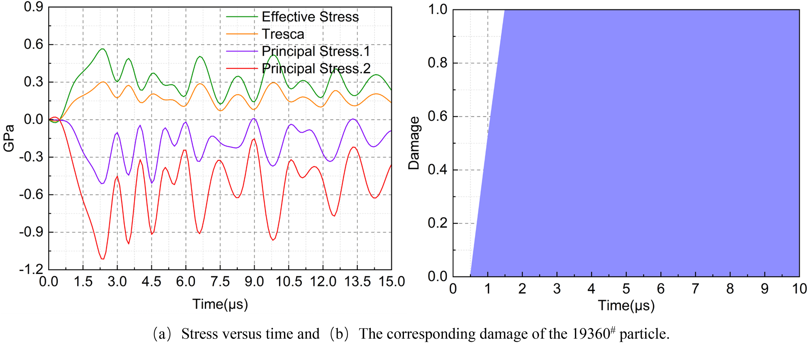
The variations of stress and damage versus time for 19360# particle. (a) Stress versus time and (b) the corresponding damage of the 19360# particle.
From Figure 10(b), it could also be found that the corresponding damage value of the measured particle directly jumped from 0 to 1.0, which indicated that the rock element did not undergo obvious plastic deformation and was an instantaneous sudden failure, the essence of which was due to the fact that under the action of huge transient water hammer pressure, the compressive and shear stresses on the rock element were several times of the compressive and shear strength of the rock, far exceeding the critical stress value that the rock element could bear, resulting in brittle failure of rock element in the upper part of the crushing zone. To sum up, the failure type of the upper rock element in the crushing zone was brittle failure caused by compression-shear stress.
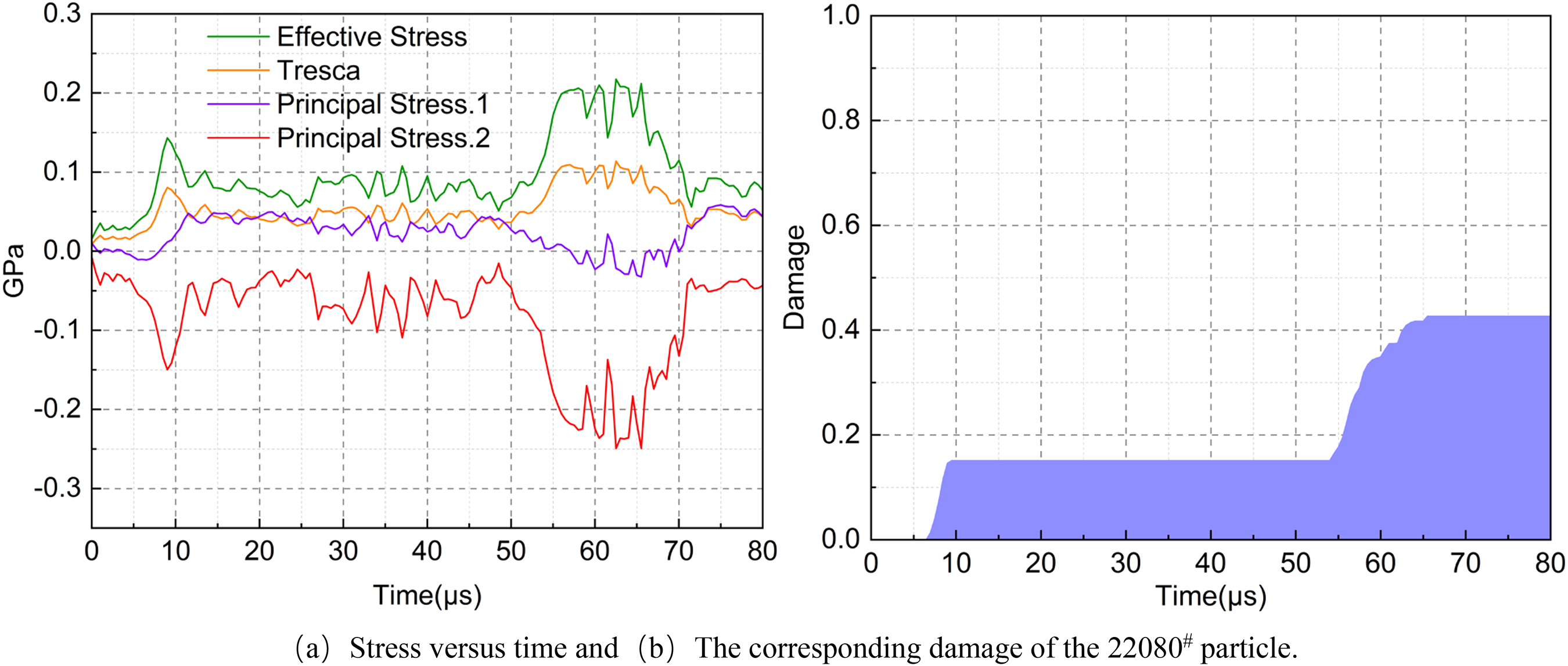
The 22080# particle was located in the damage field on the right side of the water jet, and Figure 11 showed the trend of its stresses and damage values with time. It could be seen from Figure 11(a) that the principal stress on particle during the whole impact process was mainly negative (at 11.5 μs, the tensile stress on the particles was very small, which was ignored), indicating that the particle in this area was mainly in the compression state. The compressive stress on the particle at 9.5 μs was 155 MPa, the shear stress was 77 MPa, and the effective Mises stress was 150 MPa. Under the combined action of the three, the damage value of the measured particle in the rock increased from zero to 0.13, forming a preliminary damage accumulation. Subsequently, all three stresses decreased to the extent that they were insufficient to produce effective plastic accumulation. With the propagation of the transverse stress wave, all three stresses increased in the period from 16.5 μs to 25 μs, and the particle continued to produce plastic damage accumulation. Until 25 μs, the stress of particle 22080# reached its maximum value and then nearly dropped to 0. This indicated that the element had been completely destroyed, as shown in Figure 11(b), and the corresponding damage value increased from 0.155 to 1.0. In conclusion, the failure type of rock element in the damage field on both sides of water jet was plastic cumulative damage failure mainly caused by compressive stress and shear stress.

The variations of stress and damage versus time for 22080# particle. (a) Stress versus time and (b) the corresponding damage of the 22080# particle.
The 19799# particle was located in the lower part of the rock crushing zone, and Figure 12 showed the trend of its stresses and damage values with time. It could be seen from Figure 12(a) that the principal stress suffered by the particle had both negative and positive values until 40 μs, and mainly negative values after 40 μs throughout the impact process. It indicated that the particle in this region was in the state of both tension and compression at first, and then transformed into the state dominated by compression. At 21.5 μs the particle was subjected to a compressive stress of 126 MPa, a tensile stress of 53.1 MPa, a shear stress of 89.3 MPa, and an effective Mises stress of 156 MPa. Under the combined action of the above stresses, the damage value of the particle measured in the rock increased rapidly, and the damage value increased to 0.7 at 46 μs, forming the first stage of plastic damage accumulation, as shown in Figure 12(b). With the propagation of the longitudinal compressional stress wave, the 19799# particle continued to produce plastic damage accumulation at 57 μs, and the stress of the particle decreased rapidly to 0 at 72 μs, which indicated that the element had been completely destroyed, as shown in Figure 12(b), and the corresponding damage value increased from 0.7 to 1.0. In summary, the failure type of the rock element in the lower part of the crushing zone was the first stage of plastic damage accumulation caused by a combination of compressive, shear and tensile stress, and then the plastic cumulative damage failure caused by compressive and shear stress.

The variations of stress and damage versus time for 19799# particle. (a) Stress versus time and (b) the corresponding damage of the 19799# particle.
The 15344# particle was located in the derived crack zone of rock, and Figure 13 showed the trend of its stresses and damage values with time. It could be seen from Figure 13 that the selected rock element mainly experienced two damage stepwise accumulation during the whole impact process, and both damage value saltations occurred within the tensile time period of the rock element. As shown in Figure 13(b), the damage value of this particle was platform-shaped in the time period of 22.5 μs–46 μs, and the plastic damage accumulation was very small, while the tensile stress was zero in the corresponding time period in Figure 13(a), indicating that the contributions of compressive and shear stresses to the damage accumulation in this time period were very small, and both damage stepwise accumulations were caused by tensile stresses. The tensile stress applied to the particle at 16 μs was 44.1 MPa, which was greater than the tensile stress of the rock. Under this tensile stress, the damage value of the selected particle increased to 0.27, forming the first stage of plastic damage accumulation. As the stress wave propagated, the tensile stress on the particle was 30 MPa at 46 μs, and the plastic damage continued to accumulate until 59.5 μs, when the stresses on the particle decreased rapidly. The stresses of the particle dropped to zero at 70 μs, which indicated that the element had been completely destroyed, as shown in Figure 13(b), and the corresponding damage value increased from 0.3 to 1.0. To sum up, the failure type of the particle in the derived crack zone of rock was a plastic cumulative damage failure caused mainly by tensile stress.

The variations of stress and damage versus time for 15344# particle. (a) Stress versus time and (b) the corresponding damage of the 15344# particle.
The 15797# particle was located in the main crack zone of rock, and Figure 14 showed the trend of its stresses and damage values with time. From Figure 14(b), it could be found that the corresponding damage value of the measured particle directly changed from 0 to 1.0, which indicated that there was no obvious plastic deformation of the rock element, and it was a transient sudden failure, the essence of which was due to the stress wave generated under the action of huge transient water hammer pressure at 26.5 μs, the peak tensile stress transmitted to the particle was 56 MPa, which was much larger than the critical tensile stress value that the rock can withstand, resulting in the cracking damage of the rock element in the main crack zone and increasing its damage value to 1.0 at 44 μs. As shown in Figure 14(a), the tensile stress of the corresponding particle rapidly decreased to 0, which indicated that the particle had been completely destroyed. In conclusion, the failure type of rock element in the main crack zone was brittle failure mainly caused by tensile stress.

The variations of stress and damage versus time for 15797# particle. (a) Stress versus time and (b) the corresponding damage of the 15797# particle.
Failure mechanism of rock under in-situ stress
In order to compare and analyze the damage mechanism of element at the same position under in-situ stress, a in-situ stress condition of 30 MPa was chosen for research. The 19360# particle was located at the upper part of the crushing zone on the rock surface directly below the water jet, and Figure 15 showed the variation trend of its stresses and damage values with time under 30 MPa in-situ stress condition. Comparing Figures 10 and 15, it could be seen that the damage trend of the particle under 30 MPa in-situ stress was almost the same as that without in-situ stress. It could be seen from Figure 15(a) that the principal stress on the particle was always negative throughout the impact process, indicating that the particle in the crushing zone was always in a compressed state. The compressive stress on the particle at 1.5 μs was 586 MPa, the shear stress was 181 MPa, and the effective Mises stress was 362 MPa. Similarly, all three were greater than the compressive strength, shear strength and yield stress of the rock, respectively, resulting in instantaneous compressive-shear failure in the rock crushing zone, and the corresponding damage increased from 0 to 0.96, which was consistent with 2 μs to 1.0. During the whole dynamic impact process of water jet, the maximum compressive stress suffered by 19360# particles was 1.07 GPa and the maximum shear stress was 290 MPa. The high-intensity compressive stress at the beginning of the impact directly leaded to the formation of a high-density shear stress field at the impact point.

The variations of stress and damage versus time for 19360# particle. (a) Stress versus time and (b) the corresponding damage of the 19360# particle.
It could be seen from Figure 15(b) that the corresponding damage value of the measured particle changed from 0 to 1.0 in a very short time, which indicated that the rock element did not undergo obvious plastic deformation and was an instantaneous sudden failure, the essence of which was the same as when there was no in-situ stress, due to the fact that under the action of huge transient water hammer pressure, the compressive and shear stresses on the rock element were several times of the compressive and shear strength of the rock, far exceeding the critical stress value that the rock element could bear, resulting in brittle failure of rock element in the upper part of the crushing zone. To sum up, the failure type of the upper rock element in the crushing zone was brittle failure caused by compression-shear stress under in-situ stress condition.
The 22080# particle was located in the damage field on the right side of the water jet, and Figure 16 showed the trend of its stresses and damage values with time. Compared with Figure 11, it could be seen that the damage evolution of the particle differed greatly between the two cases, and its macroscopic appearance was that the presence of in-situ stress limited the development of the width of damage field of rock. From Figure 16(a), it could be seen that the principal stress of the particle was positive or negative throughout the impact process, indicating that the particle in this area was in the compression state and the tensile state at the same time. The compressive stress on the particle at 9 μs was 150 MPa, the shear stress was 80.6 MPa, and the effective Mises stress was 146 MPa. Under the combined action of the three, the damage value of the measured particle in the rock increased from zero to 0.15, forming a preliminary damage accumulation. Subsequently, all three stresses decreased to the extent that they were insufficient to produce effective plastic accumulation. In the period of 11.5 μs–50 μs, the tensile stress was present and reached 45.6 MPa, but it could be seen from Figure 16(b) that the existence of tensile stress did not form an effective damage accumulation because the presence of in-situ stress greatly enhanced the tensile strength of the rock, so that the tensile stress that could form damage in the absence of in-situ stress was not sufficient to form an effective plastic damage accumulation in the presence of in-situ stress. With the propagation of the transverse stress wave, all three stresses increased from 54 μs to 65.5 μs, and the particle continued to accumulate plastic damage, as shown in Figure 11(b), and the corresponding damage value increased from 0.15 to 0.43. Until 65.5 μs, the stress of particle 22080# decreased rapidly, and then the damage value of the particle remained at a constant value of 0.43. In summary, the failure type of rock elements in the damage field on both sides of water jet under in-situ stress was plastic cumulative damage mainly caused by compressive stress and shear stress. Due to the existence of in-situ stress, the development of the width of rock damage field was limited, and there was no failure at the remote location away from water jet.
The variations of stress and damage versus time for 22080# particle. (a) Stress versus time and (b) the corresponding damage of the 22080# particle.
The 19799# particle was located in the lower part of the rock crushing zone, and Figure 17 showed the trend of its stresses and damage values with time under 30 MPa in-situ stress condition. It could be seen from Figure 17(a) that during the whole impact process, the principal stress of the particle was both negative and positive before 30 μs, and was mainly negative after 30 μs, indicating that the particle in this area was in a state of co-existence of tensile and compression at first, and then entered a state dominated by compression. The particle was subjected to a compressive stress of 131 MPa, a tensile stress of 54.4 MPa, a shear stress of 89.1 MPa, and an effective Mises stress of 159 MPa at 21.5 μs. Under the combined effect of the above stresses, the damage value of the particle measured in the rock increased rapidly to 0.88 at 53 μs, as shown in Figure 17(b). With the propagation of the longitudinal compression stress wave, the stress of the particle dropped rapidly at 70 μs, at which time there was a slight increase in the damage of the particle due to the collision between particles because of the stress wave effect, which increased to 0.92 at 72 μs. After 72 μs, the stress did not dropped to zero, but still fluctuated slightly, which was due to the existence of in-situ stress, and the stress state of rock element was more complex than that without in-situ stress. In conclusion, the failure type of rock element in the lower part of the crushing zone was plastic cumulative damage failure caused by the combination of compression, shear and tensile stress under the condition of in-situ stress. In addition, the particles near the edge could not reach the complete failure state, because the in-situ stress limited the evolution of damage field depth.

The variations of stress and damage versus time for 19799# particle. (a) Stress versus time and (b) the corresponding damage of the 19799# particle.
The 15344# particle was located in the derived crack zone of rock, and Figure 18 showed the trend of its stresses and damage values with time under 30 MPa in-situ stress condition. It could be seen from Figure 18 that the selected rock element mainly experienced two damage stepwise accumulation throughout the impact process, the first being was the initial arrival of the compressive stress wave at 10.5 μs, and the damage of the particle accumulated to 0.06. As shown in Figure 18(b), the particle damage accumulation occurred again at 16 μs, at this time the particle was subjected to a compressive stress of 161 MPa, shear stress of 94 MPa, Mises effective stress of 183 MPa, tensile stress of 21.4 MPa, much less than the tensile stress of the particle without in-situ stress of 44.1 MPa. Furthermore, the existence of in-situ stress greatly enhanced the tensile strength of rock, the tensile stress of 21.4 MPa to which the particle was subjected was not sufficient to form an effective plastic damage, and the accumulation of damage to the particle throughout the impact process was mainly caused by compressive and shear stresses. With the propagation of the stress wave, the damage value of the particle was stabilized at 0.414 at 59 μs. Comparing Figure 13, it could be seen that the damage evolution of the particle differed greatly between the two cases, and its macroscopic appearance was that the existence of the in-situ stress greatly limited the growth of the rock damage field. To sum up, the failure type of rock element in the derived crack zone under in-situ stress was the compressive-shear cumulative damage caused by compressive stress and shear stress, as opposed to the plastic cumulative damage failure caused mainly by tensile stress when there was no in-situ stress, the damage mechanisms of the two cases were totally different.

The variations of stress and damage versus time for 15344# particle. (a) Stress versus time and (b) the corresponding damage of the 15344# particle.
The 15797# particle was located in the main crack zone of rock, and Figure 19 showed the trend of its stresses and damage values with time under 30 MPa in-situ stress condition. Comparing Figure 14, it could be seen that the damage evolution of the particle had a big difference in the two cases. In the absence of in-situ stress, the failure type of the particle was sudden brittle failure, and the final damage value of the particle was only 0.5 in the presence of in-situ stress. The macroscopic representation was that the presence of in-situ stress greatly restricted the development of rock damage field. From Figure 19(b), it could also be found that two main damage step accumulations occurred in the selected rock element throughout the impact process, the first one being at the initial arrival of the 16 μs compressive stress wave when the damage of the particle accumulated to 0.03. As shown in Figure 19(b), the damage accumulation of the particle occurred again at 26.5 μs, when the compressive stress to which the particle was subjected was 131 MPa, the shear stress was 86 MPa, the Mises effective stress was 156 MPa, and the tensile stress was 42.2 MPa, which was less than the tensile stress of 56 MPa to which the particle was subjected when there was no in-situ stress. Moreover, the tensile strength of rock was greatly enhanced due to the existence of in-situ stress, the tensile stress of 42.2 MPa to which the particle was subjected was not sufficient to form sudden brittle failure, and the accumulation of damage to the particle throughout the impact process was mainly caused by compressive and shear stresses. As the stress wave propagated, the damage value of the particle was stabilized at 0.5 at 70 μs. In conclusion, the failure type of rock element in the main crack zone under in-situ stress was the compressive-shear cumulative damage caused by compressive stress and shear stress, as opposed to the brittle failure caused mainly by tensile stress when there was no in-situ stress, the damage mechanisms of the two cases were totally different.

The variations of stress and damage versus time for 15797# particle. (a) Stress versus time and (b) the corresponding damage of the 15797# particle.
From the above analysis, it could be seen that the damage failure type of rock impacted by water jets in the absence of in-situ stress was the coexistence of compression-shear damage and tensile damage, in which the tensile failure caused by tensile stress increased the damage field range of the rock to a great extent. However, under the action of in-situ stress, the failure type of rock impacted by water jet was mainly compression-shear failure, because the existence of in-situ stress limited the development of rock tensile stress. In addition, the existence of in-situ stress greatly enhanced the tensile strength of rock, so that the tensile stress that could form failure in the absence of in-situ stress was not sufficient to form effective damage accumulation failure in the presence of in-situ stress. The above two points were also the fundamental reasons why the damage field of the rock was suppressed when there was in-situ stress, and the inhibition effect increased with the increase of in-situ stress.
Conclusions
Damage evolution law and failure mechanism of rock impacted by high-pressure water jet under in-situ stress condition were investigated using the rate-dependent constitutive model based on SPH algorithm. From the results of a series of numerical experiments, the following conclusions were obtained:
Through the visual hillside topography of the three-dimensional surface projection, it could be seen that the number of rock damage elements gradually decreased with the increase of in-situ stress, indicating that the existence of initial in-situ stress had a strong inhibition on rock fragmentation. The degree of inhibition of rock damage by in-situ stress was quantified by calculating the attenuation rate δi of the damage element under different in-situ stresses. The damage attenuation rates corresponding to initial in-situ stresses of 5 MPa, 10 MPa, 15 MPa, 30 MPa, 45 MPa, and 60 MPa were 6.4%, 13.6%, 19.7%, 24%, 39.6%, and 43%, respectively. The in-situ stress had little influence on the surface damage width, and its value decreased gradually with the increase of in-situ stress. When the in-situ stress was greater than a critical value, the surface damage width of rock tended to a constant value. The attenuation of the maximum widths of damage could be divided into two stages, the first stage was the rapid decay stage and the second stage was the slow decay stage. This macroscopic appearance was due to the presence of in-situ stresses that limited the initiation and expansion of damage cracks in the rock, which in turn leaded to a rapid decrease in the maximum damage width of the rock. The attenuation rate of the maximum damage width of the rock slowed down, when the in-situ stress was greater than a certain critical value, and the main reason for the reduction of the damage width at this stage was that the in-situ stress increased the dynamic damage strength of the rock, so that the damage field width generated by the water jet under the same conditions was smaller. The greater the in-situ stress was, the smaller the mean damage depth of rock was, which almost showed a linear attenuation trend, and played a leading role in the number of damage particles. The reason for the attenuation of the mean damage depth was that the presence of in-situ stress limited the initiation and propagation of rock damage cracks, and at the same time, the in-situ stress increased the dynamic failure strength of rock, so that the depth of damage field produced by water jet under the same conditions was smaller. The damage mechanism of rock impacted by water jet under in-situ stress was of great engineering and scientific significance to accelerate the application of water jet breaking rock in deep engineering. The failure type of the upper rock elements in the crushing zone was brittle failure caused by a combination of compressive stress and shear stress with or without in-situ stress. The damage and failure types of rock elements at both sides of the water jet and at the lower part of the crushing area were very similar when there was in-situ stress or not, both of which were plastic cumulative damage and failure mainly caused by compressive stress and shear stress. The difference was that the existence of in-situ stress limited the growths of the width and depth of the rock damage field, and no damage has been formed at the remote location away from the water jet. the damage mechanism of rock elements in crack zone was completely different with or without in-situ stress. The failure type of rock element in the main crack zone without in-situ stress was brittle failure mainly caused by tensile stress, and the damage type under in-situ stress was cumulative damage mainly caused by compressive stress and shear stress. In the absence of in-situ stress, the failure type of rock element in the crack-derived zone was plastic cumulative damage failure mainly caused by tensile stress, while under the condition of in-situ stress, the damage type was compressive shear cumulative damage caused by compressive stress and shear stress. The existence of in-situ stress greatly limited the development of tensile stress in rock. In addition, the existence of in-situ stress greatly enhanced the tensile strength of rock, so that the tensile stress that could form failure in the absence of in-situ stress was not sufficient to form effective damage accumulation failure in the presence of in-situ stress. Due to the opacity of the rock, we cannot directly observe the damage evolution inside the rock. In the future, efforts should be made to strengthen the development of transparent hard rock materials or the study of in-situ CT tests in order to intuitively observe the dynamic damage evolution of water jet impacting rock.
Footnotes
Author contributions
Fuwei Liu: conceptualization, methodology, writing—original draft preparation; Yansen Wang: writing—review and editing, supervision, project administration; Guoxuan Song: investigation, data curation, validation, formal analysis, visualization all authors have read and agreed to the published version of the manuscript.
Acknowledgments
This research work was financially supported by the National Key Research and Development Program (Grant no. 2022YFC3005902), the Fundamental Research Funds for the Central Universities (Grant no. 2021GJZPY15), the Graduate Innovation Program of China University of Mining and Technology (Grant no. 2023WLKXJ189), the Postgraduate Research & Practice Innovation Program of Jiangsu Province (Grant no. KYCX23_2748).
Declaration of conflicting interests
The author(s) declared no potential conflicts of interest with respect to the research, authorship, and/or publication of this article.
Funding
The author(s) disclosed receipt of the following financial support for the research, authorship, and/or publication of this article: This work was supported by the National Key Research and Development Program (grant no. 2022YFC3005902), the Fundamental Research Funds for the Central Universities (Grant no. 2021GJZPY15), the Graduate Innovation Program of China University of Mining and Technology (Grant no. 2023WLKXJ189), the Postgraduate Research & Practice Innovation Program of Jiangsu Province (Grant no. KYCX23_2748).