
Abstract
Background:
Fault-Tolerant Control Systems (FTCS) are used in critical and safety applications to improve performance and stability despite failure modes. As a result, costly production losses related to unusual and unplanned shutdowns can be prevented by incorporating these systems in the critical process plant machines. The Internal Combustion (IC) engines are highly used process plant machines and faults in their sensors will cause their shutdown instigating the need to install FTCS in them.
Introduction:
In this paper, an Active Fault-Tolerant Control System (AFTCS) based on a Fuzzy Logic Controller (FLC) is suggested to improve the reliability of the Air-Fuel Ratio (AFR) control system of an IC engine.
Methodology:
For analytical redundancy, a nonlinear Fuzzy Logic (FL) based observer is implemented in the proposed system for the Fault Detection and Isolation (FDI) unit for nonlinear sensors of the AFR system. Lyapunov stability analysis was used for designing a stable system in both faulty and normal conditions. To evaluate its performance, this system was developed in the MATLAB/Simulink platform.
Results:
The simulation results show that the developed system is robust under sensor fault conditions, retaining stability with a minimum decrease of AFR. This study's comparison with the existing literature demonstrates that the proposed system is effective for maintaining the AFR in IC engines during sensor faulty conditions thus reducing shutdown of engine and production loss for increased profits.
Keywords
Introduction
Fault-Tolerant control (FTC)
A fault represents an unpredictable deviation from the optimal level in a system parameter, which may degrade the performance of the system. It is a possibility that the fault may interfere with the normal operation of the device from the intended one, but it may be bearable. Faults are commonly assumed to exist in the system and cannot be avoided entirely. However, by taking appropriate steps, their impacts may be lessened. A Fault-Tolerant Control (FTC) system can withstand faults and retain the system's closed-loop efficiency in such abnormal conditions.
The FTC is categorized generally into two types which are Active FTCS (AFTCS) and Passive FTCS (PFTCS). In the AFTCS, Fault Detection and Isolation (FDI) is a major component in which an observer-based model is used to obtain an approximate value that is compared with a real sensor value to generate a residual. The residual or variation should be within an acceptable limit. If it becomes out of limit, a fault is declared, and controller reconfiguration is done after fault isolation for adaptation to new conditions as explained in.1,2 A detailed summary of the FDI unit for AFR control and software-based analytical redundancy is reported in. 3 The diagram for the FDI unit is given below in Figure 1. In this case, the controller functions online and can be capable of detecting a wide variety of faults. However, due to excessive computations, this method becomes complicated and inefficient. In addition, noise may affect the decision-making procedure of FDI, resulting in false fault declarations.
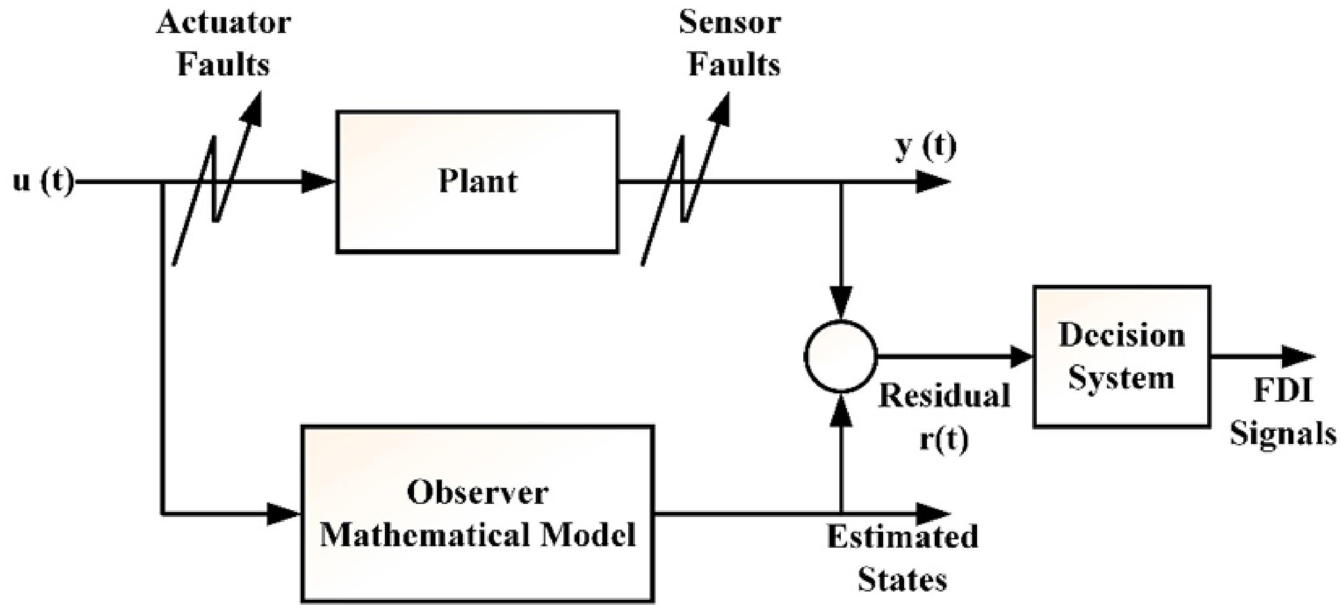
FDI unit basic structure.
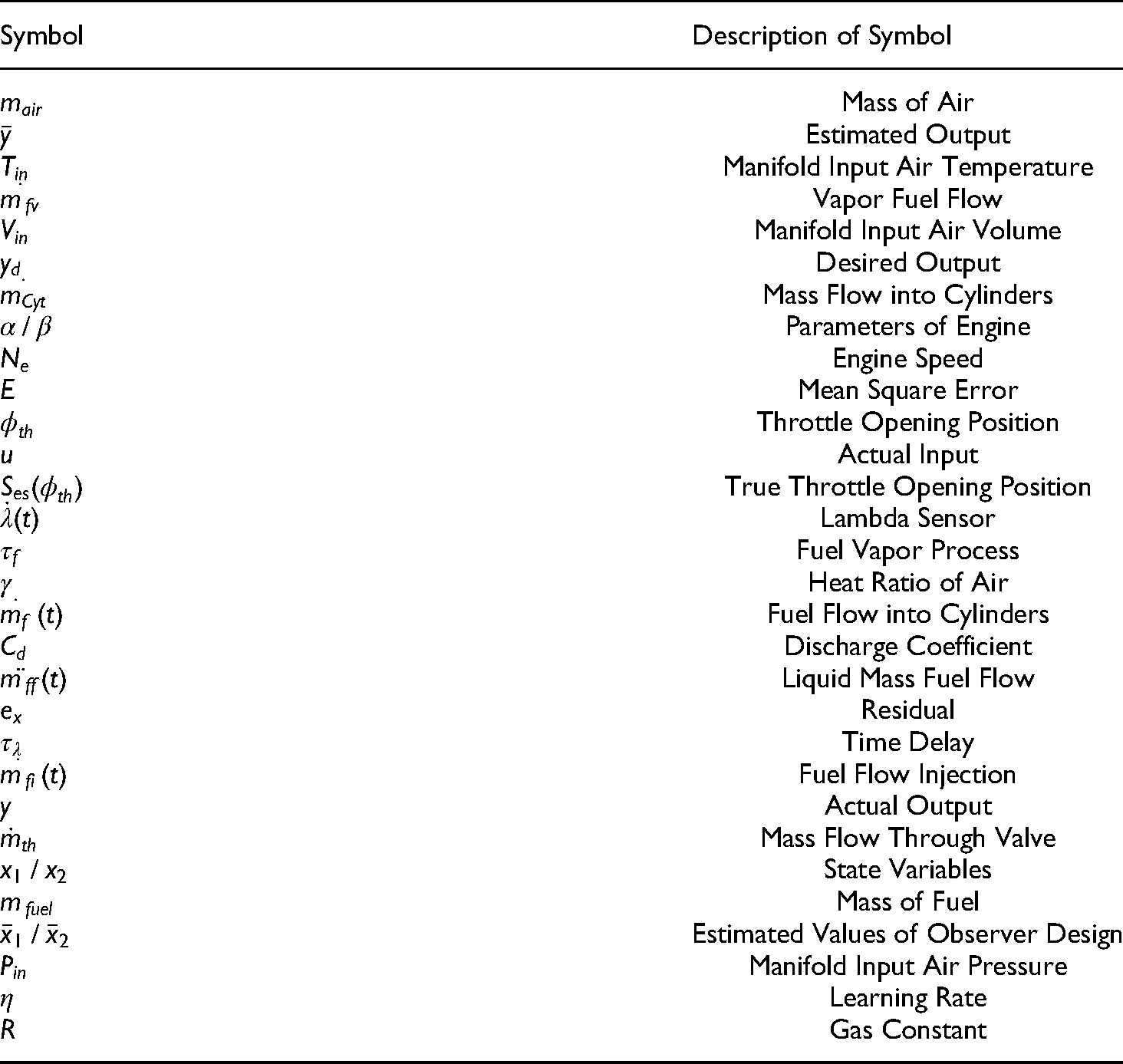
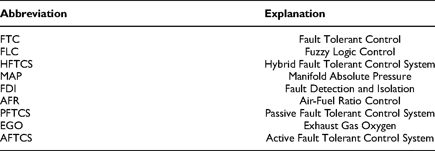
In PFTCS, there is no FDI unit, and faults are predicted during the designing stage. PFTCS has a faster response and works according to the offline design method with less computation. Arslan Amin suggested an effective technique for compensating for actuator faults with a robust Proportional Integral (PI) controller as detailed in. 4 This system will accept just a few errors that were considered throughout the design phase. A Hybrid FTCS (HFTCS) system is a combination of these two approaches that are called HFTCS. HFTCS reacts rapidly to faults in safety applications using the PFTCS feature and then improves later in post-fault conditions using the AFTCS property as described in.5,6 Advanced hardware redundancy was used in 7 for aircraft elevator control systems in the condition of a sensor fault. In linear systems, FTC schemes are extensively noted. The FTC of the known and unknown model parameters of high-speed train dynamics was studied by Tao and Xu in. 8 Soban Ahmed in 9 illustrated reliable speed control for permanent magnet DC motor with AFTCS and hardware redundancy in the switches. The list of symbols and abbreviations used in this paper are provided in Table 5 and Table 6 respectively.
The list of symbols.
List of abbreviations.
Fuzzy logic control
The Fuzzy Logic Control (FLC) techniques typically decompose a complex system into many subsystems according to the experience of human system experts. In the meanwhile, a series of basic control laws are used to simulate the human control technique in each local operating area. FLC offers an exact solution to engineering problems that are too complex or ill-defined to be addressed analytically, and are difficult to solve because their boundaries are not hard and crisp, and evidence is ambiguous, imperfect, uncertain, and imprecise. Sensor measurements provide numerical data, while human experts and operators provide linguistic data as described in. 10 The structure of an FLC is shown below in Figure 2. FLC uses fuzzy inference, fuzzification, and defuzzification techniques. Fuzzification is the process of converting a crisp input variable into a linguistic variable. Function memberships, which define a range of importance as well as a degree of membership, appreciate this transition. The method of combining all rule outputs is known as aggregation. The weighted values associated with the output linguistic variable derived as a result of fuzzy inference must be converted and modified to crisp variables regularly during the defuzzification process explained in. 11

Simple structure of FLC.
As described in, 12 an FLC-based technique is utilized to improve a hybrid system without taking into account the backup system. This design used a combination of wind, solar, and batteries. The use of FLC membership functions increased the convergence rate in this study. Stefek suggested an FLC-based complete optimization strategy for a robotic system in. 13 The genetic algorithm is used in combination with the FLC to reduce energy consumption, and the results show that a 110 percent reduction in energy consumption was obtained in this study. Lakmesari suggested a gradient descent and FLC-based controller for inverted pendulums in his research in. 14 A fourth-order inverted pendulum system was used in this study. In this study, the Sliding Mode Control (SMC) and feedback linearization approach was used.
A review of the publication entitled FLC approach to flood detection system prediction in 15 shows that an FLC model for flood detection system forecasting utilizing If-then rules is quite useful. Water level and environmental conditions are used in this article as input and control mechanisms are used as an output, and a total of 25 rules for the flood prediction phase are defined. Poonam has shown in 16 that the room cooler configuration can comprise more than one input and output value. This paper presented 2 different input variables which are humidity and temperature, and three desired outputs, the speed of the cooling fan, the speed of the water pump, and the speed of the exhaust ventilator. Mustafa's review in 17 shows the working of FLC in the washing machine. This study shows that 4 input variables and 5 output variables are established together and with eighty-one laws to classify the relationship between different factors.
AFR control of internal combustion engine:
Internal Combustion (IC) engines are the mechanical equipment to convert the chemical energy of fuel into mechanical rotational energy by combustion. They are classified into Spark Ignition (SI) and Compression Ignition (CI) engines. The ignition plugs are utilized for the process of combustion in SI engines, while combustion is done only by compression instead of the ignition plugs in CI engines. The four-stroke, gasoline-powered, homogeneous-charge, spark-ignition engine is the most popular IC engine. It works by converting the chemical energy into mechanical rotational energy, which is then used to operate the compressor and alternators. In our research, we have assumed the SI IC engine only. These engines are the most common types of heat engines used in automobiles, ships, aircraft, and trains.18, 19
The ratio of air mass to fuel mass is known as an air-fuel ratio (AFR) explained in.
20
The mathematical expression of the AFR can be written as follows.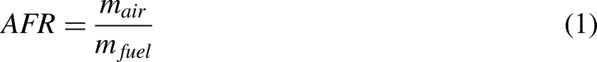


AFR mixing system of SI IC engine. 20
Air flows through the filter to eliminate dust, other unwanted particles, and its flow is regulated using a throttle valve. With the help of a fuel filter, the fuel is purified and the pressure of this fuel is controlled as per the engine's need by the regulator. After this, both fuel and air are mixed and transferred to combustion engine cylinders. Faults in the sensors can produce improper combustion and eventually cause the engine to shut down. The engine shutdown would further affect the operation and result in a loss of output, thereby lowering revenues. Increased engine downtime in the repair of faults would also increase production losses.
Four important sensors used in the AFR control systems are given below:
Different methods for controlling the AFR of IC engines were found in the literature. Carbot-Rojas provided a survey on various issues related to IC gas engines, which include modeling, usage of biofuels, control laws implementation, and simulation explained in. 22 The control law for AFR is structured by using the nonlinear model of Takagi-Sugeno. In Anjum's work as shown in, 23 for AFR control robust smooth super twisting method is applied with decreased chattering issues. In Wu and Tafreshi's work in, 24 FSM based controller is implemented for a lean-burn spark-ignition engine that is based on model-free plus doesn't involve any system characteristics. Another review that is based on the mean value of the engine model has decreased chattering problems and noise issues smooth super-twisting algorithm for the AFR control in. 25 Pace and Zhu's works in 26 explained a complete detail of AFR. In 27 a unified FTC was proposed for controlling the AFR of the IC engine. This work was well explained with the help of both hardware and analytical redundancy. The Multi-Input Multi-Output (MIMO) SMC system is implemented in AFR and is contrasted with the multi-loop Proportional Integral and Derivative (PID) controller to illustrate its improved results. Li's work in 28 suggests a PI-like fuzzy knowledge-based AFR controller which is robust to faults and self-tuning components.
Marius proposed a linear parameter variable controller for managing the AFR of an IC engine in the. 29 To manage the AFR, he used a series of these controllers. As described in, 30 Chen used estimate theory to manage the AFR of an IC engine. His study is focused on a single-cylinder engine, but it can be applied to multi-cylinder engines as well. Shiwei proposed second-order SMC for IC engine AFR control in his research in. 31 With the assistance of this second-order sliding mode control, he has demonstrated that the suggested system maintains the value of AFR under all conditions. Alippi developed a neural network-based technique for AFR control in. 32 Recurrent neural networks with external feedback were used in this research. Cervantes-Bobadilla explained in 33 a methodology that is made with the help of model predictive control and PID control with the neural network is used for the generation of the hydrogen gas used for SI IC engines. The fuzzy sliding-mode approach is described in, 34 based on model-free in the absence of having any system functionality with higher performance in regulation. An advanced FTC system for AFR by Arslan Amin covering both sensor and actuator faults is reported in. 35
The main contribution of this research work is the development of an FLC-based observer in the AFTCS for the highly nonlinear sensors of the AFR control system of an SI IC engine and this type of controller is not used so far in the literature. The key reason for utilizing FLC in this work is that it deals with control and decision-making problems that are difficult to model mathematically. The FLC is better than other controllers because it updates its parameters on each control cycle. The use of FLC improves the system's maintainability by reducing tedious mathematical calculations and allowing for more efficient nonlinear control system design. Because of its simple control structure, efficient design, superior durability, and strong anti-interference ability, the FLC provides high accuracy and speedy operation without the need for a precise model. The FLC approach tends to be very useful where the systems are too complex to be evaluated by traditional quantitative techniques or where the available sources of knowledge are represented wrongly, uncertainly, or qualitatively. So, FLC management can be used as a step towards an agreement between the traditional precise analytical control and decision-making like a human. 36 Previously many methods have been utilized for AFR control of IC engines like linear regression, lookup tables, Artificial Neural Network (ANN), and Kalman Filter (KF). Linear regression and KF were found for the limited linear range of the MAP sensor. Lookup tables and ANN have high computational costs and require powerful controllers. In this work, we adopted the FLC method to cover the MAP sensor's entire nonlinear range, and it is also more computationally efficient. The simulation results demonstrated that the proposed system remains stable and robust even when the AFR was slightly reduced due to sensor faults. In comparison to earlier studies, the proposed method was more efficient and faster for fault robustness and was based on the MAP sensor's nonlinearity.
The remaining part of the paper is designed as follows: Section 2 covers research methodology. In section 3, results and discussions are described A comparison with current works is addressed in section 4, and the conclusion is given in section 5.
Research methodology
FLC-based AFTCS has been developed for the AFR system in the Matlab/Simulink environment using the existing available model with preliminary function explained in.37, 38 One by one, each sensor is given a fault, while the others remain normal. In this research, engine running speed is kept constant at 300 r/min according to the Matlab model's design speed. We have used constant speed in this research work as the engines mostly run at constant speed in the process plant, and the 300 r/min of speed is provided to a controller by the FDI unit when the speed sensor stops working. Load variations and their impact on speed are not considered as the paper is more focused on developing FLC based AFTCS system. The available Matlab model lookup tables (LTs) are used to derive data for the MAP sensor and the throttle sensor at 300 r/min. The FLC technique is used to achieve nonlinear relationships between the MAP sensor and the throttle sensor. FDI unit utilizes these relationships of nonlinear nature to generate estimated value of faulty sensors.
Modelling of system:
AFR control dynamics can be divided into three categories: sensor dynamics, fuel dynamics, and air dynamics as explained in. 39
Dynamics of Air:
The dynamics of air intake are explained using conservation of the mass theory and ideal air gas theory as follows


Dynamics of fuel:
The fuel dynamics are explained as follows


Sensor model
The model includes a variable time delay caused by the transmission of the gas flow from the cylinder to the lambda sensor. This time delay is determined by the engine speed, Ne. The AFR is measured using a normal EGO sensor. The dynamic of the lambda sensor is represented as
39
:
Equation 15 represents the speed of engine Ne (t) with a time delay.
State space representation
The representation of the model in state space is given as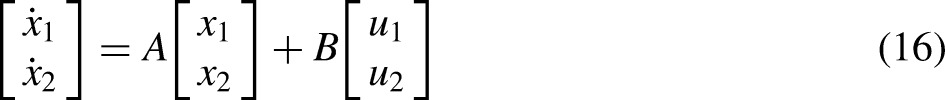


Observer design
The process can be defined in the form of state space as illustrated in observer architecture for the AFTCS system by Wang in.
42


Controller design
For mathematical fault modeling and observer setup, a detailed description is given below. Noise, drift, bias, and gain are the most common types of sensor faults. To reduce the impact of these faults, AFTCS is built using state-space representation. A brief study in
43
shows the IC engine's state-space representation, which is given below:


In the case of estimated state variables, the equation (34) comes into the following form.


Flowchart working of FLC based observer.
Stability proof
To ensure that the controller functions correctly, we use the Lyapunov proof to verify its stability. For functional operation, the control system's reliability must be maintained. This FLC-based control method employs a direct Lyapunov methodology to demonstrate the stability of the system.
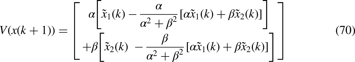
The Lyapunov function is defined as follows:


The flowchart of the proposed FLC-based AFTCS is provided in Figure 5.

Flowchart of proposed AFTCS.
The system compares sensor values and determines the sensor-to-observer value threshold. If there isn't a fault in values, the engine performs properly. If a single sensor fails; the error signal goes out of the threshold. In place of the value of the faulty sensor, the FDI unit sends the estimated value produced by the FLC-based observer to the control unit of the engine. The faulty sensor's predicted value is provided to the model with analytical redundancy. It is assumed that the switching and reconfiguring would take zero seconds. Practically, there will be a delay in the controller computations. The limitations are that it only considers full-type failures of sensors ignoring partial faults. Partially faulty components that produce partial outputs are not taken into account and will be considered in future research.
Results and discussion
Implementation of suggested AFTCS in the Matlab model of IC engine is described in Figure 6. This model consists of the following four sensors which are MAP, EGO, throttle, and speed sensor. The fault is manually inserted into the system by the Fault Injection Unit (FIU). The controller receives the new estimated value generated by the FLC observer which is based upon the data from the other functional sensors in the FDI unit.
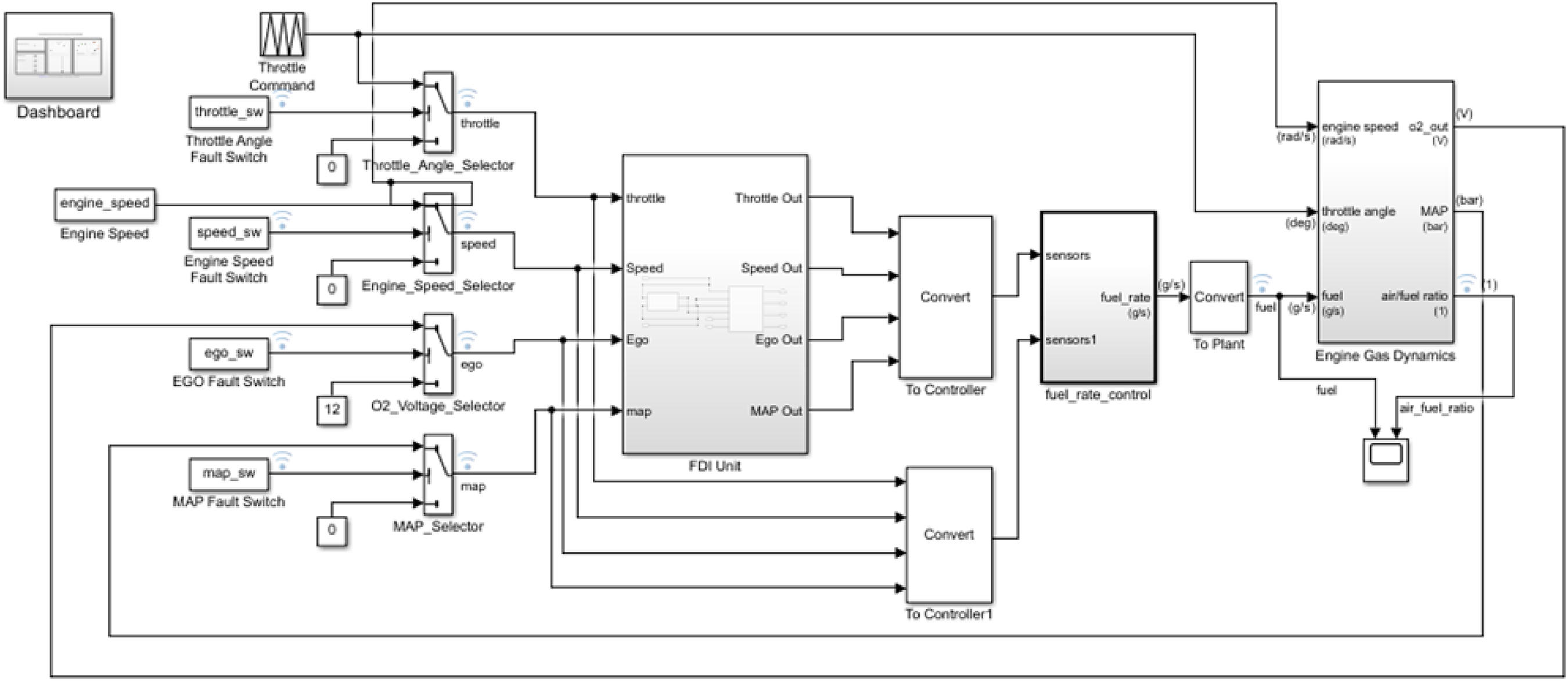
Matlab implementation diagram of AFTCS.
The FDI block is responsible for locating, isolating, and setting the faulty value parameter, as illustrated in Figure 7.

Internal diagram of FDI unit.
The FDI unit comprises of reconfiguration and estimation block. Figures 8 and 9 illustrate the internal block of the estimating and reconfiguration unit. The estimation block works such that during the faulty condition, MAP estimated value is generated from the healthy throttle sensor, and similarly throttle estimated value is generated during its fault from the healthy map sensor. For speed sensor fault, the operating speed of the model 300 r/min is supplied and for EGO sensor fault, full voltage scale value 12 V is supplied.

Estimation unit block diagram.

Reconfiguration unit block diagram.
Reconfiguration block determines the residual from healthy sensor value and estimated value. If the residual exceeds the threshold, an error is declared, and the FDI unit provides the FLC-based estimated value to the controller to satisfy the condition of fault tolerance.
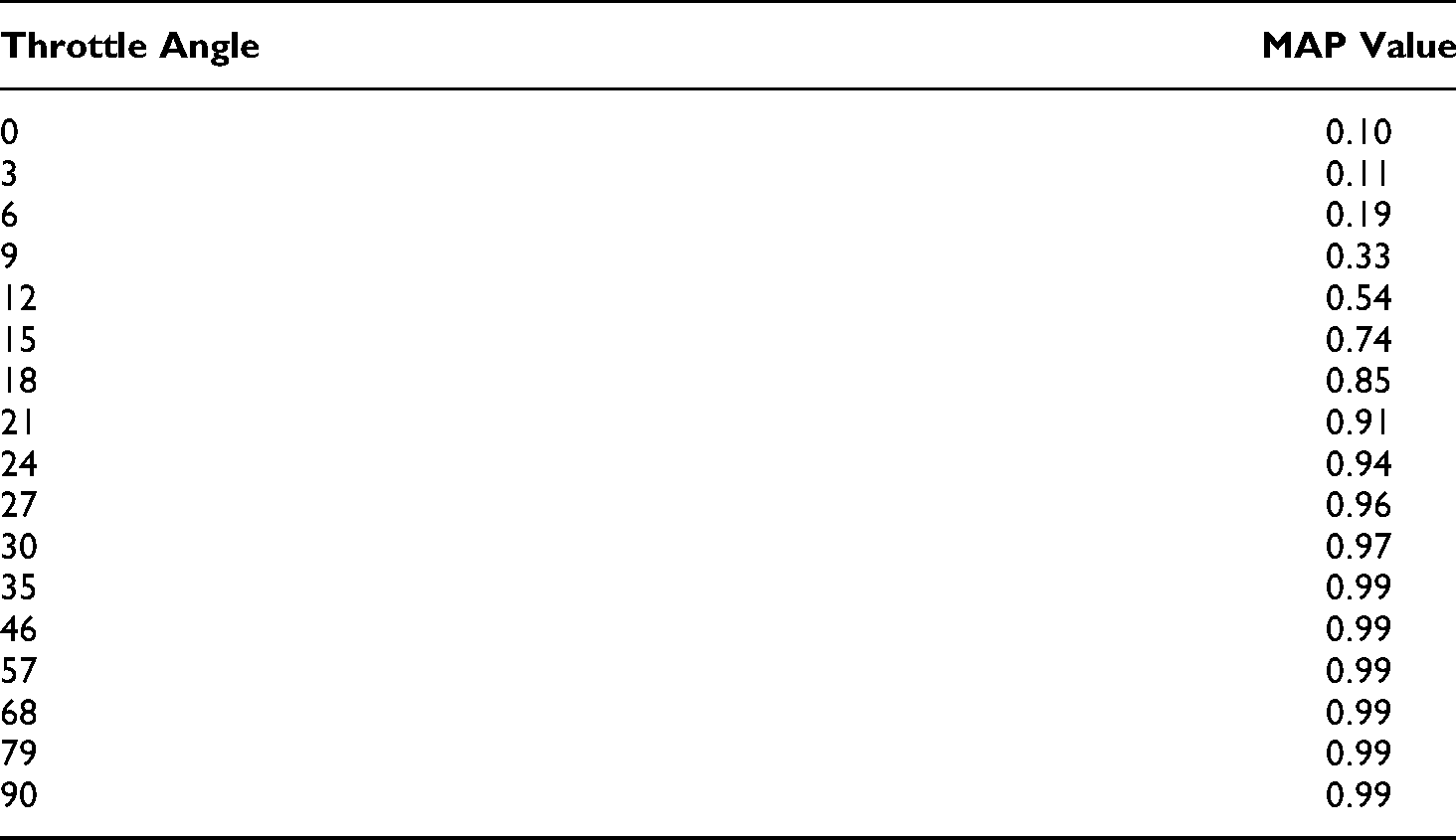
The estimating unit provides all of the estimated values. In this estimating unit, FLC based observer has been used to generate all of the estimates. Depending on data extracted from the model's lookup tables, the fault estimation unit is made using FLC. Table 1 shows the MAP estimation using the throttle angle at 300 r/min speed. Similarly, Table 2 shows the throttle angle estimation using the MAP value at 300 r/min speed.
Throttle Angle and MAP relationship at 300 r/min.
MAP and throttle Angle relationship at 300 r/min.

This paper describes a way for applying a rule-based FLC to a system. The FLC must be designed before the simulation can be conducted in Matlab/Simulink. The FIS editor is used for this simulation. The FLC toolbox is used to produce the Fuzzy Interface System (FIS) file. FLC is based on “if…then” rules that transform inputs to output. A fuzzy system's rules propose a set of overlapping patches that connect various inputs to various outputs.
The fuzzy system approximates a mathematical function or a cause-and-effect equation. Figure 10 display the membership function for MAP input and throttle output. Figure 11 displays the membership function for throttle input and MAP output. The design of an FLC requires the selection of Membership Functions. A rule base is formed when the relevant membership functions are selected. A fuzzy controller's set of language rules is its most important component. In this study, the FLC controller has one input and one output membership function. The MAP sensor value is used as an input to derive the throttle value and the throttle value is used as an input to derive the MAP value. For MAP estimation, there are a total of 28 rules, whereas, for throttle estimation, there are 19 rules constructed. When one of the sensors fails, the other sensor will provide an approximated value calculated using the FLC approach. For input-output membership functions identification, the parameters of the membership function are tuned for a stable and good sample of the system behavior. The fuzzy interference system is used to adjust the membership function parameters, which adjusts both the input and output membership functions.

Membership function for MAP input Throttle output.

Membership function for throttle input and MAP output.
The fuzzy input and output analysis for MAP and throttle estimation are shown in Figure 12. Input/output analysis for throttle estimation is shown on the left side and input/output analysis for MAP estimation is shown on the right side of the figure.

Input and output analysis for MAP and throttle estimation.
Figure 13 shows the results of the designed AFTCS under normal and faulty state. The fault is introduced into each sensor one at a time, while the others remain healthy.

Performance of FLC based AFTCS.
When a fault in any single sensor is injected by the FIU, its behavior is observed at a time of 5 s due to the internal warm delay of the engine as shown in Figure 13. This graph shows that AFR is disturbed after fault injection for a while but it becomes stable quickly due to the supply of the estimated value generated from the FLC-based mathematical observer. In normal conditions, the AFR is maintained at a value of 14.6, and under faulty conditions, it reduces to 11.7 which is called a rich mixture. Despite the degraded performance of the system in faulty conditions, the stability of the system is maintained and thus the aim of fault tolerance is fulfilled.
Comparison with existing work
A detailed comparison of newly designed observers with existing work is explained in this section. In this research paper, we introduced a full AFTCS design with a specific FLC-based FDI unit. Many studies have been already conducted for the AFTC design such as the usage of the linear regression, lookup tables, kalman filter, and ANN in recent research. All of these techniques have advantages but also have drawbacks such as the high computational cost of lookup tables and ANN. Linear regression and KF were found for the limited linear range of the MAP sensor. In this work, we adopted the FLC method to cover the MAP sensor's entire nonlinear range, and it is also more computationally efficient. As a result of the experimental analysis fault diagnosis, FLC-based AFTC was found to be a better approach. Tables 3 and 4 offer a comparison of FLC estimation performance.
Estimation of MAP using FLC based observer.

Throttle estimation using FLC based observer.

These tables show the predicted throttle and MAP sensor data, as well as the RMS error, which is decreased significantly with FLC. With the help of these tables, it has been proven that the proposed FLC-based method is much more efficient than previously used techniques.
Conclusion
In this paper, fuzzy logic control-based AFTCS was proposed for the highly nonlinear sensors of the AFR control system of an SI IC engine. In the FDI unit, the FLC-based observer was designed to provide analytical redundancy. Lyapunov stability was used to develop a stable system for both faulty and normal conditions. Previously many methods have been utilized for AFR control of IC engines like linear regression, lookup tables, Artificial Neural Network (ANN), and Kalman Filter (KF). Linear regression and KF were found for the limited linear range of the MAP sensor. Lookup tables and ANN have high computational costs and require powerful controllers. In this work, we adopted the FLC method to cover the MAP sensor's entire nonlinear range, and it is also more computationally efficient. Matlab/Simulink was used to develop the proposed system. The simulation results demonstrated that the proposed system remains stable and robust even when the AFR was slightly reduced due to sensor faults. In comparison to earlier studies, the proposed method was more efficient and faster for fault robustness and was based on the MAP sensor's nonlinearity.
Future research may also include using advanced analytical redundancies like Artificial Neuro-Fuzzy Control (ANFC), and Recurrent Neural Networks (RNN) with convergence theory and hardware-in-the-loop verification. Nodes of each layer of RNN are linked with each other as compared to other traditional ANNs. RNNs may memorize a huge amount of data from a sequence over time because of this self-connection.
Footnotes
Acknowledgment
The authors would like to thank to colleagues for suggestions to improve the paper quality.