
Abstract
A modified sliding mode active disturbance rejection control (MSMADRC) position system is designed for small-sized tractors to solve the longer shift time and reduced shifting quality because of the inaccurately motor control used for the automatic mechanical transmission (AMT) gear shift actuator. Firstly, the control model of the motor with total disturbance is established. Then an extended observer is presented to monitor the unmodeled dynamics and various disturbances of the system in real time, at the same time the extended state and the system feedback variables are constructed as the system variables of the sliding mode control (SMC) algorithm. Secondly, a sliding mode surface instead of the nonlinear control law in the active disturbance rejection control (ADRC) algorithm is designed, which realizes the fast and accurate tracking of the position. What's more, the stability of the control system is proved by Lyapunov theory. Lastly, the simulation results demonstrate that the position control precision by MSMADRC is higher 37% than by SMC and higher 75% than by ADRC. Furthermore, the response speed of MSMADRC is the fastest, it only takes about 0.7s.
Introduction
Agricultural tractors can be used as a power source for various field operations and is regarded as one of the vital implement in farm mechanization and as a versatile machine both for agriculture and farmer. 1 With the development of modern agriculture, tractors are rapidly developing towards automation and intellectualization. 2 Automatic gear shifting is therefore one of the important development trends for agricultural tractors. 3 As we know, agricultural tractors have to cope with working conditions which are more complex and demanding than those experienced by other ground vehicles. Usually, tractors move on uneven soils at low speed but with large traction forces, so they are equipped with power shift transmission to ensure flexibility at each speed in different working conditions. If manual gear shifting is adopted, repeated gear shifting will not only cause operator's discomfort because of its excessive limbs intervention but also reduce the life of clutch. What's more, tractors will stop unexpectedly because of inappropriate gear shift failing to transmit continuous power to the driving wheels. 4 Therefore, to improve work efficiency and reduce driving effort, power shift transmissions enabling the automatic shifting of gears are gradually proposed and used.5,6 Automatic gear shifting really can reduce driver work intensity for repetitive shifting operations. It can free the driver from the frequent gear shift and make the driver focus more on the operation of the implements. As a result, Automatic gear shifting not only improves the quality and efficiency of field work but also reduces fuel and power loss caused by improper manual gear shifting operations. 7
As for the design of a control system for automatic gear shifting, there are some achievements for ground vehicles, but only little dealing with gear shift for agricultural tractors are available. The main reason is that there are different demands for the gear shift because of the variability of the load and broad range of working conditions. Li et al 2 proposed a novel power shift transmission based on hydro-viscous drive technology and control strategy for automatic starting of the tractor matching the power-shift transmission. To achieve high transmission efficiency, they established the powertrain dynamical model, analyzed the shifting processes and proposed coordinated control strategies for upshift and downshift processes with changing multiple clutches. 8 In their recent research paper, 9 four-parameter gear shifting schedules were developed for tractor with different types of agricultural implements and recursive least squares algorithm was used for real time identification of the changing characteristic of draught force, by which realized the automatic gear shift and energy saving. For a high-power agricultural tractor, Mara Tanelli et al. 10 designed a transmission control system based on single clutch and double clutch gear shifts respectively. The control system can provide good shifting performance in all operating conditions. Satyam Raikwar et al. 11 proposed a power shuttle transmission system for an agricultural tractor by using MATLAB as a simulation platform. They established the model of the individual component of power shuttle transmission system and integrated them as a whole vehicle model.
Usually, hydraulic power regulated by proportional solenoid valve is used to control the gears and realize the power shift transmission for giant tractors. For small-sized tractors, electric shift with advantages of high speed and reduced the shift time is alternative mode to realize gear shift, it only uses the motor as the power source. Clutch separation, combination and shift action can be achieved through the control of the motor. But the control accuracy of this kind of shift is low and needs to be properly controlled, that is also the focus of the research on electronic shift control. In Zhang et al. 12 study, to meet the speed and stability requirements of the motor control system, they employed a fuzzy PID control algorithm to the motor control and greatly improved the shift quality. SMC has been recently used in a number of studies for controlling the position of motor. Shenye et al. 13 designed a sliding mode controller to track the position of AMT shift actuator. Li et al. 14 proposed a position and force switching control scheme for gear shift based on SMC method. The combination sleeve can reach the desired position quickly with a small resistance at the beginning and the end of gear shift process. Temporelli et al. 15 proposed a dual SMC to control clutch pressure with the electromechanical clutch actuator. In, 16 an adaptive sliding-mode-control-based model predictive torque control for induction motor was proposed and the optimized exponential reaching law can adjust the switching gain adaptively. In 17 sensorless field oriented control based on switching linear feedback structure of sliding mode control plugged with model reference adaptive system was presented for induction motor. Homaeinezhad et al. 18 proposed a position braking tracking control based on discrete time SMC, by which the DC motor can be controlled in position tracking mode and torque tracking mode respectively. To control the position of a DC motor, SMC based on uncertainty and disturbance estimator is presented. 19 What's more, ADRC has the advantages of active disturbance rejection and handling parameter uncertainties, which make it a strong candidate for industry control applications. 20 Hao et al. 21 proposed a linear/nonlinear active disturbance rejection control switching control strategy and a parameter tuning strategy. To cope with the high-order disturbance and enhance the dynamic tracking performance of the servo systems, Liu et al. 22 put forward an integrated method, in which finite-time convergent nonlinear function and novel extended state observer are designed. Yang et al. 23 proposed an ADRC strategy based on improved particle swarm optimization-genetic algorithm. And first-order and the second-order ADRC are designed for the different order of the bearingless induction motor system respectively. Sun et al. 24 used ADRC to adjust the motor torque to control the regenerative current accurately in the current closed-loop control mode. Madonski et al. 25 designed an ADRC with novel characterized of concise and practically appealing form of the control action for DC motor system. The control system demonstrated performance of improved tracking precision and disturbance rejection. For the established fifth order system model of the valve-controlled hydraulic motor, in literature 26 an ADRC strategy was designed and the grey wolf algorithm was used to set the parameters of the three parts in ADRC. It can be seen that strategies based on SMC and ADRC have been shown great performance and promises. But the structure of ADRC is complex and needs to tune a bunch of parameters, which makes it difficult to use in practice. And it is critical for SMC to cope with the chattering caused by the switching motion of the sliding surfaces.
Automatic gear shifting is important to dynamics and economic performance for agricultural tractors. To improve the accuracy and speed of the shifting gear motor used for gearshifting as well as to cope with the influence of the uncertain parameters such as the variation of the internal parameters of the motor and the external gear shifting resistance, a position control of gear shift system for small-sized tractors adopting electric shift is presented. Motivated by the above achievements, borrowing ideas from SMC and ADRC theory, the advantage of SMC that can be integrated with other control algorithms to compensate for the weakness of each other is developed. A MSMADRC based algorithm is proposed to design the shift motor control system. The method is simple and easy to be programmed into a digital real - time embedded system. For clear illustration, the paper is organized as follows: Section ‘Analysis of gear shift’ introduces the gear shift system. The control structure and controller design method are detailed in Section ‘Control law design’. In Section ‘Stability analysis’, system stability is analyzed. Simulations are carried out to demonstrate the validity of the proposed scheme in Section ‘Simulation results’. Finally, some conclusions are drawn in Section ‘Conclusion’.
Analysis of gear shift
Principle of gear shift actuator
AMT for the small-sized SL350 wheeled tractor is designed by adding a set of electronic mechanical equipment on the basis of the traditional manual transmission. And motor is selected as power source for the gear shifting. The structure of gear shifting system is shown in Figure 1, which consists of worm, gear, shift motor and transmission control unit (TCU).

The structure of gear shift system.
The shift motor will rotate after receiving the command from the TCU. And the torque output from the motor is transmitted to the sector gear after reduced the speed by the worm and gear. The movement of the sector gear is transmitted through the transmission rod to the rotation of the shift finger. Then the shift finger drives the reverse shift fork to complete the shift operation.Considering the working conditions full of vibration and direct displacement signal requirement, angular displacement sensor is preferable choice rather than the encoder, so angular displacement sensor installed at the end of worm gear shaft is used to measure the angular displacement of worm. The electric gear shifting system inherits the advantages of traditional manual transmission and combines simple structure with high transmission efficiency and low manufacturing cost.
Shift motor modeling
As for the gear shifting system, motor is one of the key element affecting the shift time. In this paper a low-voltage and cheap DC motor is selected as shift motor, it demonstrates higher reliability, easier initialization processes and more flexibility in position compared to AC motors.
27
And the angular displacement of the motor is controlled by the input torque. The dynamic equation of the motor can be written as

Control law design
Structure of proposed control system
As mentioned above, the output angular displacement of the shift motor is crucial to realize the precise gear shift, the control accuracy and robustness to the load changes of the motor control system are more important. So the objective of position control of the gear shift is to precisely track the set angular displacement as well as keep the shift motor operating steadily. To this end, the overall architecture of the MSMADRC algorithm for angular displacement is organized, as shown in Figure 2.

The overall architecture of MSMADRC algorithm.
MSMADRC controller consists of a sliding mode controller, expansion state observer (ESO), and disturbance compensator. ESO is the heart of the controller, it observes the uncertainties existing in the system as total disturbances and eliminates the influence of the disturbances in the form of disturbance compensation. The observed state variables are employed to design the sliding mode controller, which will greatly simplify the design of the sliding mode controller. What's more, to reduce the chattering phenomenon, the adaptive sliding controller is introduced by designing the sliding surface and sliding reaching law.
Active disturbance rejection controller design
ADRC aims to accommodate the disturbances in a way that the design can be executed without a detailed mathematical model. As in Figure 3, the idea of ADRC is to actively estimate the disturbance and cancel it by the control action.
28
Using the disturbance before the process represents the total disturbance, From Figure 3, the response of the real motor system subjected to control action and external disturbance is

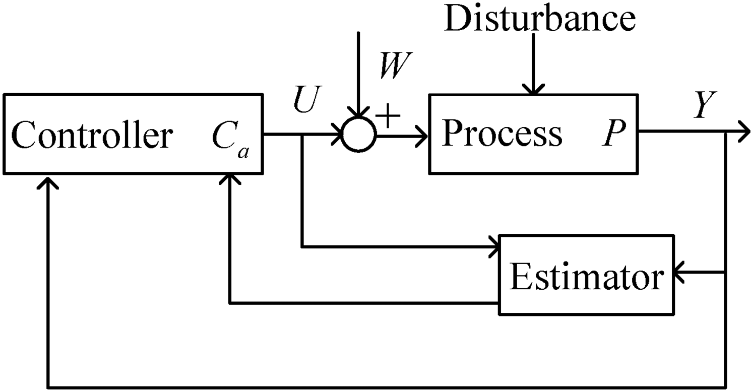
Active disturbance rejection control scheme.
Where Y is the output of the control system, P is the control process, U is the control action, W is the disturbance,

According to the basic idea of the ADRC, the second order motor system can be described as


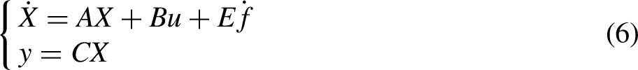
Assuming that the total disturbance f of the system is derivable, according to equation (5), a linear extended state observer (ESO) is constructed as:


The standard procedure of ADRC is firstly to design the observer gain vector as


As can be seen from equation (5), disturbance is added as an extended state and it is a real time status variable. What's more, the disturbance is estimated according to equation (7) and the estimated disturbance play a role during the controlling process as part of the controller output which can be referenced as equation (11).
It can be seen from the design procedure for the ESO that the
Sliding mode control law design
As we know, sliding mode control also is a powerful tool to handle uncertainties and disturbances. Its dynamics of the system is determined by the selected sliding surface, by which excellent robust performance can be achieved as well as high tracking accuracy. So through the fusion of sliding mode control and ADRC, not only the control performance of the system is improved but also the parameter setting for the controller is simplified.
Based on the theory of sliding mode control, the deviation between the actual measured motor angle and desired motor angle is selected as the system tracking error


Modified sliding mode control law design
As can be seen from equation (17) that


As can be seen from the above equation, there are four parameters that can be adjusted to obtain a good control performance. As for the sliding mode control, a smaller
Stability analysis
Lemma 1
30
: As for

According to the designed sliding mode surface, the Lyapunov function


Simulation results
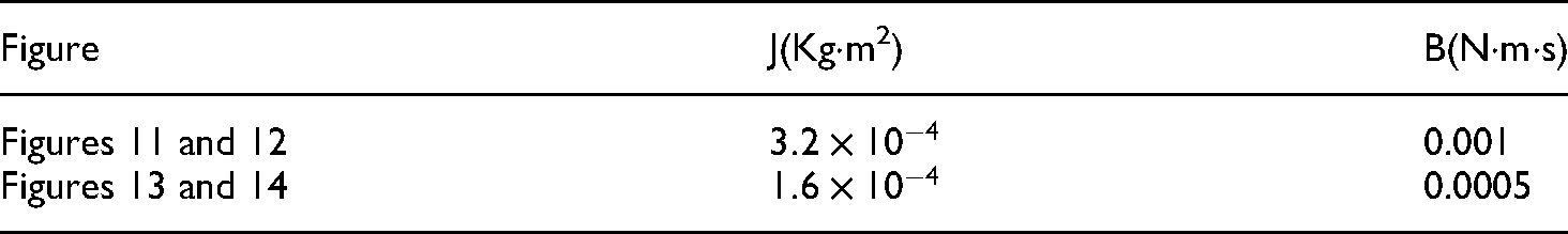
Simulations are implemented to verify the performance of proposed MSMADRC algorithm for motor position control. On the basis of the model and controller proposed above, motor model and controllers are developed on MATLAB/Simulink platform. The parameters of the selected motor can be refered in Table 1. Based on many simulation tests, the MSMADRC controller parameters are set as
Parameters of the motor.

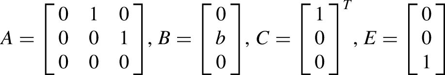
With these controller settings, the performances of the three methods are simulated. Firstly, a sinusoidal signal input is used to evaluate the tracking response of the three control methods and the simulation results are shown in Figures 4 and 5. It can be seen from the figures that the three control methods can realize the tracking to the sinusoidal signal, and the tracking error is less than 0.01 rad, which indicates that the three control methods have good dynamic tracking performance. However, the local enlarged image shows that the tracking error of traditional ADRC exceeds 0.005 rad and the tracking error of SMC and MSMADRC are both close to 0, which also shows that the combination of ADRC and SMC can effectively reduce the error and improve the control accuracy.
Tracking response to sinusoidal signal.

Tracking error to sinusoidal signal.
Secondly, in order to demonstrate the response speed and stability of the system, three control methods are carried out to track the r pulse signal without disturbance. The simulation results are shown in Figures 6 and 7. It can be seen from the local enlarged image that ADRC has the slowest response speed with 1.2 s response time. There is no steady state error but overshoot. For SMC response, it takes about 1 s to the steady state but there is a steady state error. As for the performance of MSMADRC, it only take 0.6 to the steady state as well as there is no steady state error. At the same time, control actions that are the control input torques to the shift motor of SMC and MSMADRC are shown in Figure 8. As mentioned above, for the traditional SMC, the control action will be inevitably chattering due to the presence of

Tracking response to square signal.

Tracking error to square signal.

Control action to square signal.
Thirdly, in order to verify the disturbance rejection performance of SMADRC, three methods are carried out to track the pulse signal with disturbance. The disturbance is randomly set between [0,1]. The tracking error and control actions are shown in Figures 9 and 10. From the simulation results it can be seen that when there is disturbance in the system, the control error of SMC is the largest And the ability of disturbance rejection of MSMADRC is obviously superior than ADRC and SMC. And the control actions are basically both smooth for ADRC and SMC.

Perturbed system response to square signal.

Control action to square signal.
Fourthly, to analyze the methods robustness, now suppose that there exists 100% increment for rotational inertia and coefficient of viscous friction respectively. The corresponding system outputs are shown in Figures 11–14. The model mismatched system parameters used in simulation are shown in Table 2. It can be seen from the results that for the traditional SMC method, there are always oscillations because of the existence of

Model mismatched system I tracking response to step signal.

Model mismatched system I tracking error to step signal.

Model mismatched system II tracking response to step signal.
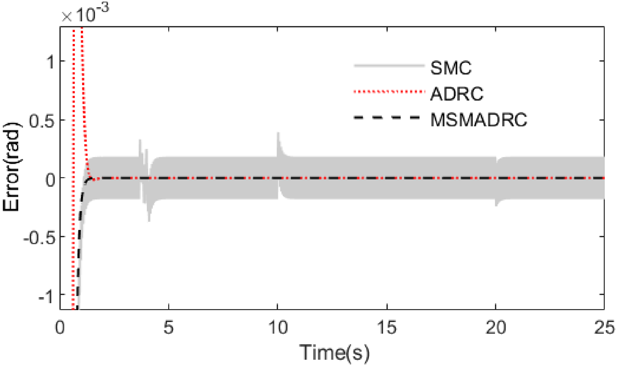
Model mismatched system II tracking error to step signal.
Model parameters used in simulations.
It can be seen from the above results that the designed MSMADRC system can accurately and quickly track the setpoint and the performances of disturbance rejection and robustness are superior to the other two methods, which can meet the requirements of rapidity and accuracy for the position control of AMT shift actuator.
Conclusion
To improve the accuracy and speed of the shifting gear for agricultural tractor AMT, a gear shift motor control system based on MSMADRC method was presented.
To cope with the unknown disturbances, extended state observer was designed by utilizing the advantage of the ADRC. The estimated disturbances and uncertainties were combined with the nonlinear state error feedback and suppressed by designing the sliding mode controller. What's more, smooth control action was obtained by adopting the continuity method based on relay characteristic to reduce chattering.
The simulation results showed that the MSMADRC method demonstrated not only higher precision, faster response but also superior robustness and disturbance rejection compared with the traditional ADRC and SMC. The superior performance indicated that MSMADRC algorithm has the promise of reducing the shift time, eliminating the power interruption and improving the shift quality of the agriculture tractor.
Footnotes
Declaration of conflicting interests
The author(s) declared no potential conflicts of interest with respect to the research, authorship, and/or publication of this article.
Funding
The author(s) disclosed receipt of the following financial support for the research, authorship, and/or publication of this article: This study is supported by the Research Foundation Project of Liaocheng University in China (318012020), and the Shandong Province Key Technologies R&D Program in China (2016GNC112014).