
Abstract
When the rock burst occurs, energy absorption support is an important method to solve the impact failure. To achieve constant resistance performance of energy absorption device, as an important component of the support, the mechanical properties of one kind of prefolded tube is analyzed by quasi-static compression test. The deformation process of compression test is simulated by ABAQUS and plastic strain nephogram of the numerical model are studied. It is found that the main factors affecting the fluctuation of force-displacement curve is the stiffness of concave side wall. The original tube is improved to constant resistance by changing the side wall. The friction coefficient affects the folding order and form of the energy absorbing device. Lifting the concave side wall stiffness can improve the overall stiffness of energy absorption device and slow down the falling section of force-displacement curve. It is always squeezed by adjacent convex side wall in the process of folding, with large plastic deformation. Compared with the original one, the improved prefolded tube designed in this paper can keep the maximum bearing capacity (Pmax), increase the total energy absorption (E), improve the specific energy absorption (SEA), and decrease the variance (S2) of force-displacement curve.
Introduction
With the upper part coal resources dried up gradually, mining projects are going deep.1–4 The characteristics of deep geostress, coal rock occurrence environment, surrounding rock stress state, and coal rock stress level have changed, which brings the tunnel support difficulty and prevention of rock burst.5–8 Energy absorption support is an important method to solve the impact failure of the support body when the rock burst occurs. 9 Energy absorption device, as an important component of the support, can release the impact of surrounding rock by rapid yield and protect the support system from damage. 10 The maximum bearing capacity, average bearing capacity, variance of force-displacement curve, total energy absorption, and specific energy absorption are important indexes for evaluating energy absorption devices, which determine the merits of energy absorption effect. 11 As an important dissipating device of collision kinetic energy, energy absorption device has been applied in almost all traffic fields, such as automobile, airplane, ship, and high-speed railway, and achieved good results.12–14 The square, circular, cellular, and foam-filled tubes have been well studied. However, these energy absorption devices have many deformation modes under the action of axial impact load, which greatly limit the effect of energy absorption.15–21 The energy absorption device commonly used in mining engineering is a kind of prefolded energy absorption device. 22 The quasi-static test and finite element analyses were conducted to multi-cell structures, and the hierarchy could improve the energy absorption.23,24 Thin-walled energy absorbers with different sections were examined under low-speed impact test. The highest absorbed energy and highest crashing force efficiency was attributed to the circular beam and simple square beam, respectively.25–29 The optimization results can improve the specific energy absorption and reduce the maximum impact capacity.
The energy absorption device induces the deformation by the fold, which deformation mode under the impact is stable, then obtain the energy absorption effect. The energy absorption device is placed at the bottom of the hydraulic support column (as shown in Figure 1), which can be directly stamped from the square plane structure and has the advantage of simple manufacturing process. In addition, the prefolded tube has a stable deformation state and a constant yield length. Therefore, it is applied in the tunnel support and can improve the impact resistance of hydraulic support. However, the force-displacement curve of the energy absorption device is up and down in the crushing process. When rock burst occurs, this kind of reaction force fluctuation phenomenon will make the hydraulic support column broken until failure. The excessive fluctuation of reaction force even brings the hazard of secondary impact to the hydraulic support and surrounding rock.

Location of energy absorbing device.
In this paper, the folding process, and mechanical properties of a prefolded tube are studied by quasi-static compression test and simulated by ABAQUS. The results show that the stiffness of concave side wall have the greatest influence on the force-displacement curve. Based on the results, the original prefolded tube is improved by thickening the concave side wall to constant resistance. Compared with the original one, the type of constant resistance energy absorption device designed in this paper can keep the maximum bearing capacity (Pmax), increase the average bearing capacity (Pmean), improve the specific energy absorption (SEA), and decrease the variance (S2) of force-displacement curve. When it is applied to the tunnel hydraulic support, on the basis of ensuring the original energy absorption effect, it greatly reduces the damage of the secondary impact caused by the excessive fluctuation of the support reaction force to the hydraulic support and the surrounding rock. Improve the impact resistance of traditional rigid hydraulic supports.
Mechanical properties of prefolded tube
Quasi-static compression test and numerical simulation
To study the bearing capacity of the prefolded tube, the quasi-static compression test was carried out. Figure 2 is the prefolded tube and size in mm. The material of prefolded tube is low carbon high strength steel. The mechanical properties are: density ρ = 7980 kg/m3, Young’s modulus E = 210 GPa, σy = 890 MPa, σu = 1050 MPa, Poisson’s ratio ν = 0.3. The friction coefficient between the loading plate of test machine and the prefolded tube is 0.1. Quasi-static compression test was carried out in the displacement control mode. The loading displacement rate was 1 cm/s.

Dimension drawing of energy absorption device (mm): (a) main view, (b) top view, and (c) numerical model of device.
Since it is inconvenient to observe the deformation of the top, bottom and inside of the energy absorption device during the test, and it is unable to analyze the change of the plastic zone, commercial finite element analysis software package ABAQUS/Explicit was applied to simulate the axial crushing process. The crushing scenario was modeled as a device standing on a stationary rigid panel and being compressed by a moving one. The stationary rigid panel was completely fixed, whereas all the degrees of freedom of the moving rigid panel were constrained except for the translational one in the axial direction of the device. Prescribed downward displacement was assigned to the free degree of freedom of the moving rigid panel to control the crushing process. Four-node shell elements with reduced integration S4R were used to mesh the tube, supplemented by a few triangular elements to avoid excessively small or distorted elements. Self-contact was employed to model the contacts among different parts of the device, and surface-to-surface contact was defined between the device and each rigid panel.
The material and loading speed used in the numerical simulation are consistent with the test. Friction was also considered and the coefficient μ was taken as 0.1. By optimizing the calculation results of different mesh sizes, the mesh with side length of 4 mm was selected to mesh the prefolded tube. The model was divided into 13,500 cells and 13,709 nodes.
Numerical simulation and test force-displacement curves and deformation diagrams are shown in Figures 3 and 4. The numerical simulation curve is close to the experimental curve, and the deformation process is similar, so the numerical simulation results can be considered accurate and reliable.
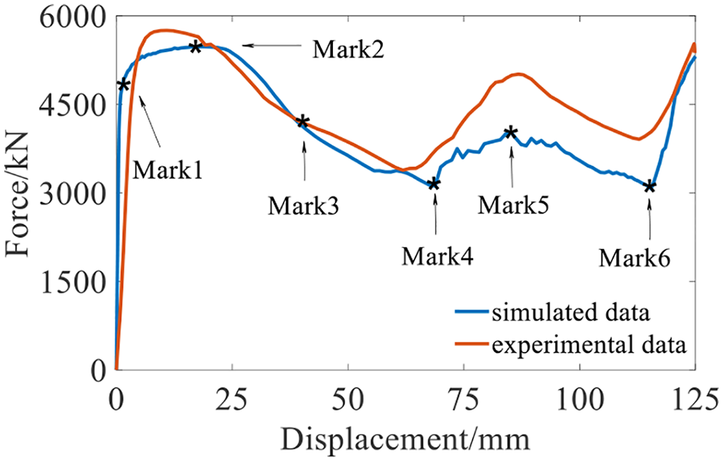
Numerical simulation and test force-displacement curves.

Numerical simulation and test deformation diagrams.
Deformation process and partial stress
According to the deformation characteristics of the energy absorption device, the force-displacement curve is divided into seven stages shown in Figure 3. For convenience of presentation, the schematic diagram of each part of device is shown in Figure 5, in the figure, the blue area is the upper-section, the red area is the mid-section, and the white area is the lower-section.

Parts of energy absorption device.
Elastic stage
The stage energy absorption device compressed 1 mm is from the initial to the Mark1 (0–1 mm), the load increases to 4797 kN. As shown in Figure 6 which is the section diagram of the equivalent plastic strain, no plastic deformation occurs in the device.

Deformation diagram of elastic stage: (a) main view, (b) back view, and (c) legend.
Mid-section bending load ascending
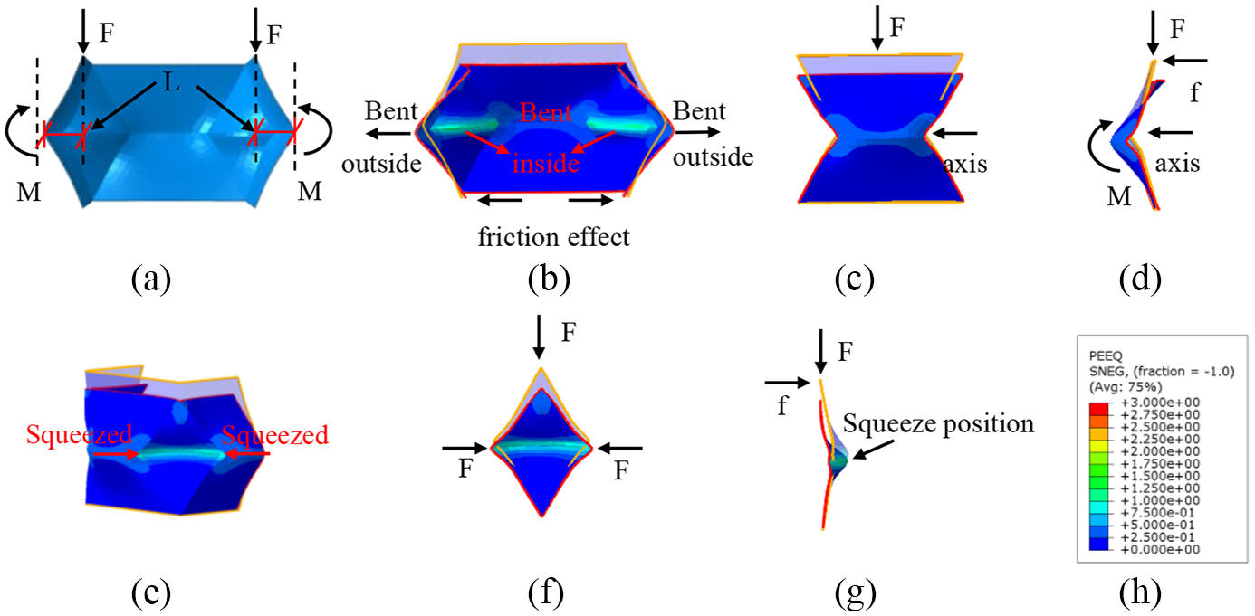
Second stage is from Mark1 to Mark2 (1–18 mm). The device is compressed 17 mm downward, and load rises to 5470 kN, up to ultimate. Due to the folding Angle of the energy absorption device, additional bending moment is generated by the action of the upper compress. Since the middle arm of the device is the longest, the additional bending moment generated in the middle is the largest, the middle part is bent first (as shown in Figure 7(a) and (b)). Due to the hardening of the material itself, the material strength increases continuously during the bending process of the device, so the force-displacement curve shows an upward trend.

Deformation of upper middle bend: (a) stress analysis diagram, (b) main view, (c) convex main view, (d) convex side view, (e) side view, (f) concave main view, (g) concave side view, and (h) legend.
Figure 7(b) to (g) is the equivalent plastic strain diagram of the second stage. To represent the deformation process more clearly, the equivalent plastic strain deformation diagram at the beginning and the end of this stage is superposed. Orange and red lines are used to represent the contour of the equivalent plastic strain nephogram at the beginning and end of this stage, respectively. The remaining diagrams in this section are represented in the same way.
The deformation of the device in this process is mainly caused by the mid-section bending deformation. The upper and lower edges of the convex side wall are in contact with the top and bottom plate of the press, so the horizontal direction deformation is less under the horizontal restraint of the friction force, it mainly manifests as vertical deformation. Under the action of upper compress and additional bending moment, the convex side wall rotates with the fold as its axis. Meanwhile, the horizontal direction deformations of the concave side wall are also less under the same friction force. However, the concave side wall is squeezed when the adjacent convex side wall rotates downward, so that the concave fold changes from a straight line to an arc in the horizontal direction (as shown in Figure 7(e)); At the same time, under the action of the top pressure, the concave side wall is in a bidirectional state of stress (as shown in Figure 7(f)), and the fold is bent inward (as shown in Figure 7(g)). For these reasons, the plastic strain of the concave sidewall fold is larger than the convex fold. It can be seen from the equivalent plastic strain value (PEEQ) that the concave plastic sidewall has an equivalent plastic strain of 0.51, and the convex fold produces an equivalent plastic strain of 0.20.
Mid-section bending load descending
From the Mark2 to the Mark3 (18–37 mm), the device is compressed 19 mm downward and load reduces to 4341 kN. The deformation reason of the energy absorption device in this stage is similar to that in the previous stage: under the action of the upper compress and additional bending moment, the device continues to bend along the middle fold. Because the material in the mid-section of the device has completely hardened, the bending stiffness is no longer increased. However, as the device is compressed, the force arm in the mid-section increases (as shown in Figure 8(a) and (b)). Therefore, the load required for bending is reduced, and there is a downtrend in the force-displacement curve.
Deformation of middle bending descending section: (a) stress analysis diagram, (b) main view, (c) convex main view, (d) convex side view, (e) side view, (f) concave main view, (g) concave side view, and (h) legend.
The deformation of the device in this process is mainly caused by the mid-section bending deformation. Under the constraint of friction, the deformation of the convex side wall is relatively small in the horizontal direction, mainly in the vertical direction. Under the action of the upper compress and the additional bending moment, the convex side wall continues to rotate taking the fold as the axis (as shown in Figure 8(b)–(d)). The horizontal deformation of the upper and lower edge of the concave side wall is small under the action of friction. Under the action of the upper compress and the extrusion of the adjacent convex surface, the fold in the middle of the concave continues to bend inward and finally forms a stable arch structure, and no longer continues to deform. Because the concave fold is in a two-way stress state, the equivalent plastic strain is greater than the convex fold, and the equivalent plastic strain of the concave side wall is 0.79, the convex fold produces an equivalent plastic strain of 0.29 (as shown in Figure 8(e)–(g)).
Load descent stage
This stage is from Mark3 to Mark4 (37–68 mm) with load reducing to 3129 kN, the device is compressed 21 mm. Due to the concave surface of the energy absorption device has been deformed into a stable arc, stiffness of the upper-section is less than that of the mid-section Under the compress action, the friction force cannot continue to maintain the force balance of the upper part, so the upper side wall begins to bend. During this process of the upper side wall, although the material hardens and the strength increases, the influence range of the bending area is limited, the bending stiffness is improved less. However, as the upper side wall bends downward, the force arm increases and the load required for bending decreases, so the force-displacement curve shows a downward trend (as shown in Figure 9(a)).

Deformation of upper bending descending section: (a) stress analysis diagram, (b) main view, (c) convex main view, (d) convex side view, (e) side view, (f) concave main view, (g) concave side view, and (h) legend.
In this process, the deformation of the device is mainly the bending deformation of the upper-section wall. Under the action of the upper compress, the convex side wall rotates to be parallel to the top rigid plate with the height of about 1/4 of the device as the axis. The lower part of the side wall is constrained by the friction, and the horizontal deformation is small (as shown in Figure 9(a)–(c)). About 1/4 of the concave side wall height bends outward under the upper compress. As the adjacent convex side wall squeezed the concave upper part, a stress concentration area is formed at the included angle, which makes the side wall at the height of 1/4 of the concave side wall change from a straight line to an outward arc in the horizontal direction. The deformation of the lower part of the side wall is small due to the restriction of friction (as shown in Figure 9(e)–(g)), during this process, the equivalent plastic strain at 1/4 of the upper part of the convex side wall increases to 0.37, and the equivalent plastic strain at 1/4 of the upper part of the concave side wall increases to 2.08.
Load ascent stage
The displacement from Mark4 to Mark5 (68–85 mm) with the load rise to 4029 kN, the device is compressed 17 mm during this stage. The upper-section wall of the device continues to deform under compressing. The convex side wall continues to bend inward, and no longer contacts with the top rigid plate (as shown in Figure 10(a) and (b)), and the stress point of the side wall changes from the overall stress point of the side wall to the stress point only on the top of the concave side wall (as shown in Figure 10(a) and (b)). Based on constant stiffness, the force arm decreases greatly, so the force-displacement curve rises.

Deformation of upper bending ascending section: (a) stress analysis diagram, (b) main view, (c) convex main view, (d) convex side view, (e) side view, (f) concave main view, (g) concave side view, and (h) legend.
In this process, the deformation of the device is mainly the bending deformation of the upper-section wall. Under the action of the upper compress, the convex side wall continues to bend inward until it no longer contacts the upper rigid plate (as shown in Figure 10(b)). The mid-section and lower section move a little. (as shown in Figure 10(b)–(d)). The top surface of the concave side wall is extruded downward under compressing to be parallel to the upper rigid plate, the middle part is slightly bent outwards, (as shown in Figure 10(e)–(g)). The equivalent plastic strain at 1/4 of the upper part of the convex surface changes little. The equivalent plastic strain at 1/4 of the upper concave increases to 2.31.
Bottom bending load descending
This stage is from Mark5 to Mark6 (85–115 mm) with load reducing to 3069 kN, the device is compressed 30 mm. Under the action of the upper compress, the friction force cannot continue to maintain the force balance of the lower part of the energy absorption device, so the lower-section wall begins to bend. During the bending process of the lower side wall, although the material hardens and the strength increases, the area at the bending position is small. The bending stiffness is improved less. However, as the lower side wall bends downward, the force arm increases and the load required for bending decreases, so the force-displacement curve shows a downward trend (as shown in Figure 11(a)).

Deformation of lower bending descending section: (a) stress analysis diagram, (b) main view, (c) convex main view, (d) convex side view, (e) side view, (f) concave main view, (g) concave side view, and (h) legend.
In this process, the deformation of the device is mainly the bending deformation of the lower-section wall. Under the action of the upper compress, the convex side wall rotates to be parallel to the bottom rigid plate (as shown in Figure 11(a)–(c)) with the height of about 3/4 of the device as the axis. About 3/4 of the concave side wall height bends outward under the upper pressure. As the adjacent convex side wall squeezes the lower part of the concave, a stress concentration area is formed at the included angle, and the side wall at about 3/4 of the concave side wall height changes from a straight line to an outward arc in the horizontal direction. The deformation of the lower part of the side wall is small due to the restriction of friction (as shown in Figure 11(e)–(g)), during this process, the equivalent plastic strain increases to 0.27 at 3/4 of the lower part of the convex side wall and 1.97 at 3/4 of the lower part of the concave side wall.
Bottom bending load descending
Exceed Mark5, it is the compression ascending section of the energy absorption device. The device has been completely compressed. The device only has compression deformation of the material (as shown in Figure 12), the load rises rapidly, and the component can no longer absorb energy if the loading continues.
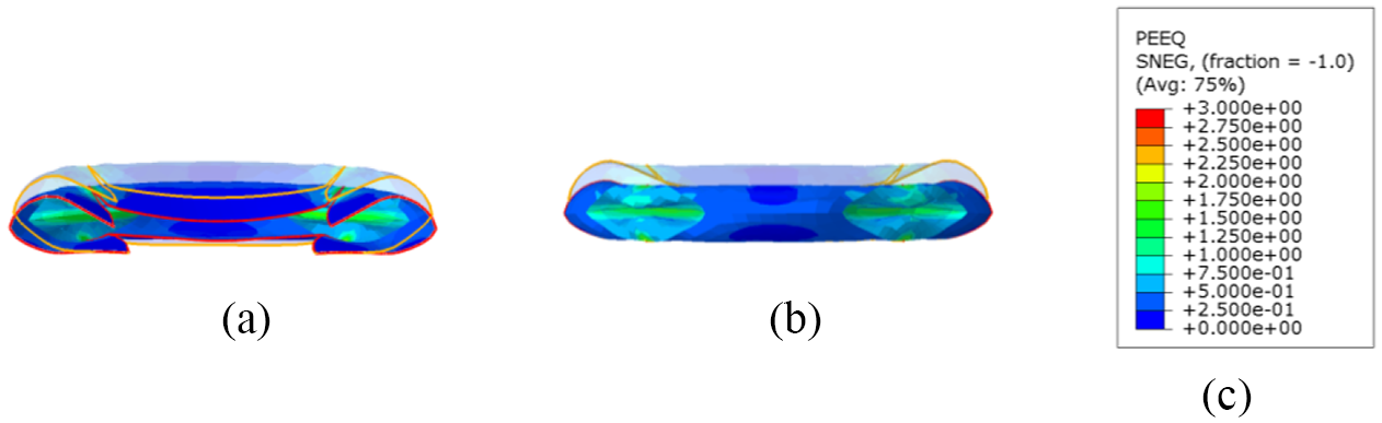
Deformation diagram of compression ascending section: (a) main view, (b) back view, and (c) legend.
The affect of stiffness
The mechanical properties of the energy absorption device are greatly affected by the stiffness of the concave side wall. According to the analysis of the mechanical properties of the device. The concave side wall of the device is always under bidirectional stress when it is squeezed by the adjacent convex side wall and the upper compress during the crushing process of the device, The plastic strain is always larger than the convex side wall, indicating that the concave side wall is more deformed than the convex side wall, which is the weak position in the device. If the stiffness of concave side wall can be improved and deformation of concave side wall can be restrained, the overall bending stiffness of device can be improved. Finally, the falling section of the force-displacement curve can be reduced.
Besides, the friction coefficient affects the frictional force, and the force controls the time when the side wall of the device begins to bend. If the friction force is large, the side wall bending time of the device is later, and the compression time in the mid-section of the device is longer. 30 While the side wall bending time of the device will be earlier, the device has a shorter compression time in the middle.
Constant resistance of energy absorption device
The principle of energy absorption support is as follows: under normal working conditions, the hydraulic support plays the role of supporting the surrounding rock. Therefore the support capacity should be available before the prefolded tube flexes and deforms. When the tunnel is impacted, the device releases the impact energy of surrounding rock by yielding deformation. To avoid the failure of the support system due to impact, meanwhile, the device always provides a certain bearing capacity in the process of being crushed, to prevent the loss of bearing capacity and the failure of tunnel.
The minimum capacity of existing device is only half of the maximum capacity. A large descending in bearing capacity may cause loosening of the tunnel due to loss of bearing capacity. Simultaneously, the reaction force rises again while the device is rapidly repositioning. This kind of violent volatility will bring secondary impact to the hydraulic support and surrounding rock, which causes the main bearing object to be transferred from the device to the upper supporting system, thereby causing the supporting system above the device to be broken and failed.
Thus, as shown in Figure 13, the force-displacement curve of the device under ideal conditions should be the constant resistance state in which the reaction force remains constant or changes little after the initial crushing. That is to say, before rock burst occurs, the device has the supporting capacity to support the surrounding rock to meet the normal working requirements of the tunnel. The device has the supporting capacity before yield deformation, that is, its force-displacement curve has a certain initial peak value. When the tunnel is impacted, the device can quickly deform and provide a constant bearing capacity, so as to reach the ideal state of releasing the impact and avoiding the stress concentration in the surrounding rock of the tunnel, and avoiding the loose damage of the roadway due to too fast unloading.

Force-displacement curve of energy absorption device in ideal state.
Design of new absorption energy device
According to the above analysis, the concave side wall of the energy absorption device has a large plastic strain under the action of top pressure and the extrusion of the adjacent convex side wall, which is the weak position of the device. After the concave side wall deforms, the whole device starts to deform, and the force-displacement curve starts to decrease. Preventing premature yield deformation of the concave side wall is conducive to enhancing the maximum bearing capacity of the device. Therefore, the stiffness of the concave side wall is improved by increasing the thickness of the concave side wall of the device, and then the maximum bearing capacity of the device is increased to reduce the falling section of the force-displacement curve. Finally, the volatility of the curve is reduced.
Since the thickness of steel used in the mold for making the device is 10 mm, for the convenience of subsequent production, the thickening thickness is chosen as 10 mm, that is, the thickness of the device is increased from the initial 10 mm to 20 mm. The thickening height is set as 1/12, 2/12, 3/12, 4/12, and 5/12 of the overall height of the device (as shown in Figure 14) to select the appropriate thickening height.

Thickening position diagram of energy absorption device: (a) top view and (b) main view.
Variances of force-displacement curves of energy absorption devices at different thickening heights are listed in Table 1. It can be seen from the table that when the friction coefficient of the contact surface is 0.1 and the thickening height is 56 mm, the variance of the force-displacement curve of the device is the smallest, which is 2.17 × 10¹¹. The force-displacement curve comparison between the new structure and the original structure is shown in Figure 15. It can be seen from the figure that the force-displacement curve of the new structure fluctuates less and basically reaches constant resistance. The comparison of energy absorption effect between the new and old structures is shown in Table 2. The total energy absorption E and specific energy absorption sea are calculated according to equation (1) and (2). Compared with the original tube, the new type of constant resistance energy absorption device designed in this paper can keep the maximum bearing capacity (Pmax), increase the average bearing capacity (Pmean), improve the specific energy absorption (SEA), and decrease the variance (S2) of force-displacement curve. Under static load, the new energy absorption device can also meet the support role of the surrounding rock. When rock burst occurs, the reaction force in the process of energy absorption and yield deformation is smoother than the original tube.
Variances of force-displacement curves related to thickening heights.


Force-displacement curves of original and new energy absorption device.
Comparison of energy absorption effect of original and new energy absorption devices.

Total energy absorption E is calculated according to equation (1) and refers to the area of compression force P under the curve of compression displacement u. Specific absorption energy SEA refers to the energy absorbed per unit mass within the effective crushing distance of the structure, which reflects the utilization of materials. Specific absorption energy is calculated according to equation (2).


Conclusions
In this paper, the deformation process and plastic strain distribution of the prefolded tube are studied by compress test and numerical simulation, then a new type of constant resistance is proposed. The conclusions are as follows:
The friction coefficient affects the folding sequence and folding form of the energy absorption device.
As the concave side wall of the energy absorption device is a parallelogram, it is unstable. Therefore, it is obviously squeezed by the adjacent convex side wall, which is in a bidirectional state of stress. The earliest yield deformation occurs, which drives the overall deformation of the energy absorption device.
Compared with the original prefolded tube, the new type of constant resistance energy absorption device designed in this paper can keep the maximum bearing capacity (Pmax), increase the average bearing capacity (Pmean), increase the total energy absorption (E), improve the specific energy absorption (SEA), and decrease the variance (S2) of force-displacement curve.
Footnotes
Author Contributions
Numerical model test, J.S. under the guidance of D.A.; investigation, J.ZH. and H.X.; writing—original draft preparation, J.S. under the help of D.A.; writing—review and editing, D.A.; funding acquisition, Y.S.
Declaration of conflicting interests
The author(s) declared no potential conflicts of interest with respect to the research, authorship, and/or publication of this article.
Funding
The author(s) disclosed receipt of the following financial support for the research, authorship, and/or publication of this article: The study was financially supported by the National Natural Science Foundation of China (no. 51474013 and 51774015) and Youth Talent Support Program of North China University of Technology.