
Abstract
The current optimization research on the connectors of prefabricated barriers uses experimental comparisons only and lacks theoretically based optimization methods as guidance. The primary objective of this study was to propose an efficient optimization approach to the connector design of prefabricated bridge barriers. This paper presents an efficient two-stage optimization approach to the connector design of prefabricated bridge barriers. In the first stage, the hybrid cellular automaton algorithm is used to perform dynamic topology optimization on the connector, and the best material distribution in the design domain is obtained. In the second stage, a kriging metamodel and genetic algorithm are combined to further optimize the size of the connector structure. With a prefabricated bridge as the engineering background, finite element models of a barrier system under impact load caused by a car crash were established. The above approach is utilized to optimize the design of the barrier connector. Results showed that the optimized connector structure greatly improved the overall performance of the barrier system while reducing the material consumption and costs. The proposed optimization approach can determine the optimal material distribution and size of the connector structure, thus providing guiding significance for the design and construction of connectors of prefabricated components.
Introduction
Installing bridge barrier is an efficient measure to ensure driving safety. 1 Compared with cast-in-place barriers, prefabricated barriers can be installed under various conditions, thereby reducing time and cost. A reliable connection is needed between a prefabricated barrier and the bridge deck to improve the integrity of the prefabricated components. Therefore, barrier–bridge connectors have become a focus of research. According to the construction, connections can be classified as bolted, grouted, and dowel bar connections.
Patel et al. 2 proposed a pre-tensioned rod connector that is inserted through the barrier and the deck. The connector is anchored to the deck by bearing plates, washers, and nuts (Figure 1(a)). The bolt connector used by the Florida Department of Transportation (FDOT) 3 (Figure 1(b)) doesn’t require much steel consumption, but subsequent studies have confirmed that such connectors are prone to stress concentration. Therefore, the challenges with the abovementioned connectors are gaining access to the bottom of the deck and the corrosion of the exposed hardware. Then, the adhesive-bonded bolt was proposed, 3 which involves drilling a hole into the deck and then inserting a threaded bolt through the barrier and into the deck. The bolt is secured with an adhesive at last. However, an issue with this connector is the anchorage strength of the adhesive used.

Connectors of bolt construction: (a) pre-tensioned rod, (b) bolt, and (c) adhesive-bonded bolt.
Grouted connections don’t require high accuracy in construction. In the grouted sleeve proposed by Ashley and Sri 4 (Figure 2(a)), extension rebars are reserved during the construction of the deck and then inserted into the corrugated pipe when barriers are hoisted. The construction is completed by grouting. The precision of the connection can be controlled by the diameter of corrugated pipes. Duchesneau et al. 5 proposed an inverted-U-shaped rebar connector (Figure 2(b)), a U-shaped steel bar is welded to the bottom steel bar of the deck, and the extended part is connected to the bottom of the barrier by grouting. The U-shaped rebar connector was optimized through experimental analysis, and the authors recommended the stud rebar connectors, 5 which have a relatively simple structure (Figure 2(c)).

Connectors of grout construction: (a) corrugated grout pipe, (b) inverted-U-shaped rebar, and (c) stud rebar.
Dowel rod connections are widely used for the integrated prefabricated systems of barriers and bridge decks. A dowel rod is connected to the steel reinforcement frame of the barrier system during prefabrication. A stainless-steel anchoring connector 2 (Figure 3(a)) anchors the inclined force-transmitting steel bars with stainless-steel heads under the bridge deck such that the barrier and the deck receive the load in concert. Due to the the use of stainless-steel rods, this connection doesn’t cost effective. Azimi et al. 6 and Sennah et al. 7 proposed a glass fiber reinforced plastic (GFRP) bar connector with head-ends (Figure 3(b)); failure tests were conducted on concrete barriers under static load to determine the optimal head-end size. Rostami et al.8–10 considered the influence of the cantilever length, the load position, and other factors on the performance of connectors. The GFRP hook connector was proposed through experimental comparison, its optimal bending angle and direction were identified through parameter optimization.

Connectors of transmission rod construction: (a) Dowel with stainless-steel head-end, (b) GFRP bar with head-end, and (c) GFRP bar with hook.
In summary, the current optimization research on the connectors of barriers uses experimental comparisons only and lacks theoretically based optimization methods as guidance. Thus, this paper proposes a two-stage optimization method for the connectors of prefabricated barriers (Chapter 2). With the first prefabricated bridge in Guangzhou as the engineering background, a dynamic finite element (FE) model of a car–barrier collision system is established (Chapter 3). The abovementioned optimization approach is used to optimize the connector (Chapters 4 and 5). The comprehensive performance of the barrier before and after the optimization of the connector is compared (Chapter 6).
Proposed optimization approach
The optimization approach of the proposed prefabricated barrier connector is divided into two stages: conceptual design and parameter design. The specific optimization process is shown in Figure 4.

Flowchart of optimization procedure.
In the conceptual design stage, based on topological optimization ideas, the hybrid cellular automaton (HCA) method is applied to the optimization design of the connector under impact load caused by a car collision to obtain the optimal solution of the material consumption and performance, thereby maximizing the realization of the structural function of the connector.
Step 1: The design domain is defined and FE analysis (FEA) is used to obtain the state information (e.g. stress, displacement, and strain energy) of each element as the basis for material update.
Step 2: The material in the design domain is redistributed according to the cellular automaton (CA) algorithm for the deletion and retention of the element. Then, convergence is checked.
Step 3: The final topology will be output when the convergence criterion is satisfied; otherwise, the iterative process continues from FEA.
In the parametric design stage, the topology obtained in the first stage is further refined. A set of optimal size parameters is obtained by combining the superior fitting effect of the kriging method and the global optimization function of the genetic algorithm (GA).
Step 4: Size parameters are selected as design variables, sample points are generated using design of experiments (DOE) based on the uniform design method, and FEA is used to calculate the design responses of the sample points.
Step 5: The sample points’ data are adopted to construct a kriging metamodel, and the function relationship between the design variables and the design responses is obtained.
Step 6: GA is used to perform global optimization based on the kriging metamodel to obtain a set of optimal design variables.
FE model establishment
Engineering background
An F-shaped concrete bridge barrier with a crashworthiness design level of 5 (according to the standard: JTG D81-2017 11 in China) was adopted for a prefabricated bridge in Guangzhou. As shown in Figure 5, the standard section of the prefabricated barrier is 6 m long and 1.1 m high, and the head-on slope is 84° to the horizontal. The angle steel is set under the barrier and welded on both sides to the bottom rebar of the barrier. The connector is composed of embedded plates and rebars. The spacing of the embedded steel bars is 100 mm. The center of the embedded steel plates is set under the angle steel. A full-length shear groove is arranged under the back of the barrier, and a horizontal stop is arranged at the end of the bridge flange plate. The shear groove of the prefabricated barrier is butted with the stopper during hoisting, and the angle steel and the connector are welded to complete the barrier–bridge connection.
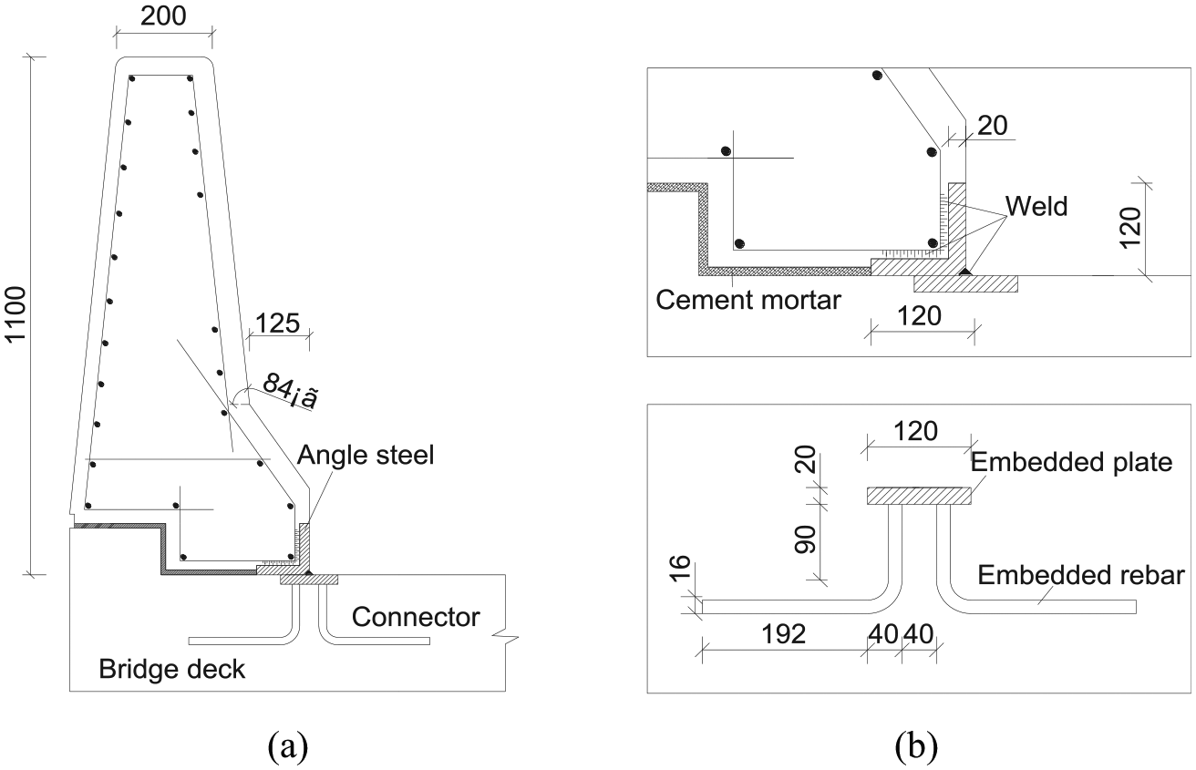
Structural drawing of prefabricated barrier in Guangzhou: (a) structure of barrier system and (b) large scale drawing of angle steel and connector.
FE modeling
Collision between a car and a barrier, which includes material damage, large deformation, and complex contact, is a strong nonlinear problem. Therefore, research on the collision problem must be based on transient, nonlinear, and contact FEA and dynamic theories. LS-DYNA is a general explicit FEA software used to analyze the nonlinear dynamic response of a 3D inelastic structure. This study combines the preprocessing function of the FEA software HyperMesh with the advantage of LS-DYNA for FEA to simulate the collision process.
The FE model of a car–barrier collision mainly includes a car, prefabricated barrier, and connector, as shown in Figure 6. According to the standard: JTG D81-2017 12 in China, for a roadside barrier of SA design level, the impact effect of a 1.5-t car running at a speed of 100 km/h can be used for the collision analysis of the barrier system. More than 80% of roadside traffic accidents have collision angles between 15° and 25°, so 20° is used as the collision angle for simulation, and the collision position is set to act on the 1/3 standard section of the barrier. This study adopts the Dodge Neon FE model provided by the Federal Highway Administration (FHWA) and the National Highway Traffic Safety Administration (NHTSA), 13 which is certified by the National Crash Analysis Center crash test for vehicle crash simulation. The mesh size is 10–30 mm, and there are 372,564 elements, including the shell, beam, and solid elements for the different parts of the FE model of a car.

FE models of different components.
The barrier part, angle steel, and connector are all modeled by eight-node solid elements (SOLID168). The element sizes of the barrier body and the angle steel are 60 and 20 mm, respectively. The connector element will undergo large deformation during the analysis process; therefore, a local mesh size of 8 mm is applied. The keyword *CONSTRAINED_SPOTWELD is used to define the weld connection between the reinforced concrete (RC) barrier and the angle steel and between the angle steel and the connector. For the boundary condition, all degrees of freedom of the nodes on the bottom of the connector and the grooves are modeled as fixed.
Material modeling and contact parameters
The material behavior of concrete in this model is represented by the concrete material model MAT_96 (brittle damage) in LS-DYNA.
14
The MAT_96 model is based on the theory of damage mechanics, which considers the integration of concrete and rebars. It can simulate the tensile cracking failure behavior of RC in a short time with a high strain rate, large deformation, and high impact under collision. The yield relationship includes the tensile stress perpendicular to the failure crack and the shear stress along the crack. Strain rate efficiency is achieved by defining the volume viscosity

Where
Material parameters of brittle damage (MAT_96).

For elastoplastic materials in high-speed-collision simulation, high strain rates can lead to dynamic hardening of materials. The piecewise linear plasticity model MAT_24 14 is suitable for FEA with large and severe deformation and a dominant strain rate. The plastic strain rate effect of MAT_24, which is a material model for angle steel and connectors, is realized by the Cowper–Symonds model, and the parameters and constitutive data refer to the literature. 14
The selection of reasonable contact parameters and friction coefficient is important for the simulation of the collision process. There are three contact issues that need to be considered: the contact between the car and the barrier, the contact of the car itself, and the contact between the car and the bridge deck. The first two types of contact problems are defined by setting the contact keywords *CONTROL_AUTOMATIC_SURFACE_TO_SURFACE and *CONTROL _AUTOMATIC_SINGLE_SURFACE, respectively. The car–bridge contact is defined by the keyword *CONTROL_RIGIDWALL, which simulates the deck ground by setting a rigid wall. According to values from the literature, 14 the dynamic and static friction coefficients between the car and the barrier are 0.2 and 0.21, respectively, and the dynamic and static friction coefficients between the tires and the bridge deck are 0.65 and 0.71, respectively.
Collision process of FEM
Figure 7 shows the collision between the car and the barrier at different time instants. The car collides with the barrier at an entry angle of 20°. After the first collision, the car climbs up the slope of the collision surface of the barrier. Then, the car begins to drive along the barrier for a period of time. A second collision occurs, and the vehicle begins to turn until it is completely out of the barrier structure.

Progression of collision during FEA simulation: (a) start of collision, (b) the car is guided along the barrier, and (c) tail collision.
Topology optimization of connector under impact load
HCA algorithm
Topology optimization is a numerical iterative procedure that finds the optimal material layout inside a fixed design domain to maximize structural performance while satisfying a set of constraints. 16 The HCA method 17 is a dynamic topology optimization method that combines CA with FEA. FEA is used for structural calculation and analysis to determine the state field of the cells, while the CA algorithm is used to update the state of the cells and obtain the material distribution in the design domain.
The CA algorithm is a mathematical model with discrete space and time. It is composed of cells, neighborhoods, cell states, and state update rules. In the solution process, the cells (elements in FEA) interact with each other and follow the same update rule, which constitutes a dynamic evolution process that changes over time. In this study, a 3D neighborhood is considered. The location information of three typical CA neighborhoods is shown in Figure 8, where

Cellular automaton neighborhoods in a 3D model: (a) Von Neumann,
In the design domain, the state of each cell

The HCA algorithm brings the structural quality to a stable state as the convergence criterion, which means the iterative optimization process converges when no further change in mass is possible.

Topology optimization problem
The definition of the field variable

Where

Where

Topology optimization model (unit: mm).
Topology optimization results
The iterative process of the topology optimization of the connector section and the mass redistribution during the process is shown in Figure 10. After 14 iterations, the topology optimization results tend to converge. The material elements at the upper ends of the design domain are gradually eliminated while the efficient bottom and middle material elements are retained. A reasonable inverted-T-shaped structure is obtained as the final topology; its volume is 35% of the design domain.

Mass redistribution and optimization iterative process.
Section size optimization
On the basis of the connector topology, specific size optimization is implemented in this section. The barrier connector is fitted with the deck through the bottom plate of the inverted-T-shaped structure. Together with the anti-pulling performance of the web, the connector provides the connection strength for the prefabricated barrier system. Therefore, four design parameters, namely, web thickness
Data of sample points.

D.O.E
Representative sample points should be selected in the establishment of the kriging metamodel, and the fitting accuracy largely depends on the DOE method. The uniform design method
19
considers the problem from the point of view of uniformity and aims to obtain the most information with the least number of trials, which is suitable for experimental conditions with a wide range of optimization variables and multiple levels. The four optimization variables are divided into five levels, and 32 sets of uniform design tests are conducted according to the uniform design table
Kriging model establishment
The kriging method 20 is a statistical prediction method that is based on a random process with a smoothing effect. It fully considers the spatial correlation of variables on the basis of certain characteristic data of several information samples inside and outside a region. The kriging method can perform a linearly unbiased minimal variance estimation to obtain prediction data of the target points. These advantages give the kriging method a superior fitting function that is widely utilized in structural optimization design, 21 reliability calculation, 22 and other fields. A kriging metamodel is composed of a regression model and a random function.


Optimization design by GA
For multi-parameter optimization problems, traditional optimization algorithms tend to fall into local optimal solutions. GA 23 efficiently searches for the global optimal solution. When the initial population (through coding) is formed, certain operations are applied to individuals in the population through fitness function evaluation. The goal is to realize the evolutionary process of survival of the fittest and thus approach the global optimal solution. SEA and the maximum principal tensile stress of the connector are regarded as the objective function and constraint, respectively. The entire optimization problem can be defined as


GA optimization process: (a) optimization process of parameters
Size optimization result
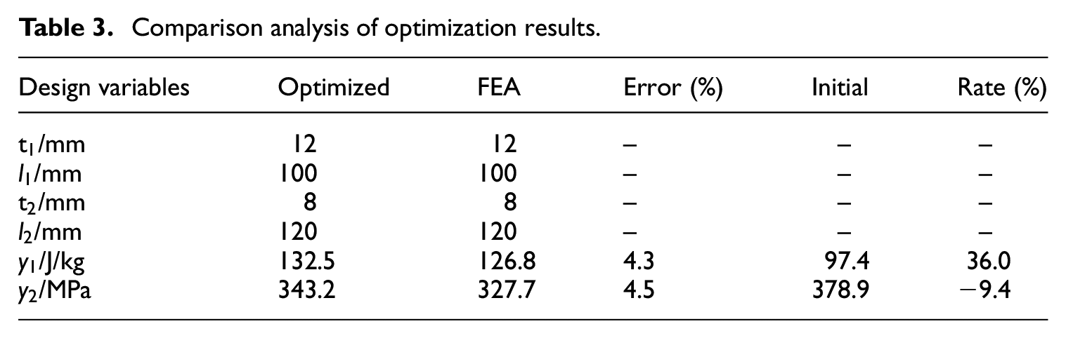
The predicted responses of the optimization variables are compared with the response values calculated by FEA to verify the fitting accuracy of the kriging metamodel. The data are shown in Table 3 The error between the optimization and FEA results is within 5%, indicating that the prediction result is reliable. Compared with their values before optimization, the steel consumption of the connector of each standard section of the barrier is reduced by 26.1%, the SEA is increased by 36.0%, and the maximum principal tensile stress is reduced by 9.4%.
Comparison analysis of optimization results.
Analysis of overall performance of barrier system
The structure before and after the optimization of the prefabricated barrier connector is shown in Figure 12. In the following, we further compare and analyze the optimization effect from three aspects: connection strength, barrier cushioning performance, and anti-overturning performance.

Comparison of connectors before and after optimization.
Connection strength
As shown in Figure 13, the stress of the horizontal section of the embedded rebars is relatively low, and the main tensile stress of the vertical section of the embedded rebars reaches the yield strength at the moment of collision, which can lead to fracture and failure of the connector. Moreover, the stress distribution of the optimized connector is evidently more uniform than initial design.

Distribution of principal tensile stress of connectors.
As shown in Figure 14, the vertical displacement of the nodes can reflect the vertical pull-out amount of the connector. The time history curve has two peaks. The connector has unrecoverable residual deformation after the collision, indicating that the material of the connector is damaged and has entered the plastic phase. The deformation of the optimized connector is much smaller than that of the original connector, which means that the connector material is still in the elastic stage, and the connection strength is still guaranteed after collision.

Time history curve of nodal vertical displacement.
Cushioning performance
As shown in Figure 15, the tensile stress mainly appears at the root of the barrier below the impact position; thus, that part of the concrete cracks, and the internal steel bars bear the impact load. Compared with the initial design, the optimized inverted-T-shaped connector structure fits firmly with the bridge deck, thereby strengthening the restraint effect on the root of the barrier. Consequently, the stress distribution of the standard section of the barrier is more uniform, and a large area of the RC helps bear the impact load caused by the vehicle collision. Furthermore, the optimized connector brings more energy absorption to the barrier system (the energy absorption values before and after optimization are 93.7 and 149.6 kJ, respectively), and the cushioning performance of the barrier is significantly enhanced.

Distribution of principal tensile stress of RC.
Anti-overturning performance
The lateral dynamic displacement value of the barrier is an important index for evaluating the stability and anti-overturning performance of the barrier system. Figure 16 shows two peaks in the time history curve, they occur at the moments of the initial collision and the tail collision, and there are residual displacements after collision. Compared with that of the initial design, the lateral dynamic displacement value of the optimized barrier system is significantly reduced during the collision process. Thus, the optimized connector gives the barrier system greater overall stiffness, thereby effectively avoiding the separation of the barrier and the bridge deck.

Lateral dynamic displacement time history graph.
Conclusions
This paper presents an efficient two-stage optimization approach to the connector design of prefabricated bridge barriers. In the first stage (conceptual design), the HCA algorithm is used to perform dynamic topology optimization to obtain the optimal topology of the connector. In the second stage (parametric design), with SEA as the objective function, a kriging metamodel and GA are combined to further optimize the size of the connector structure. The above approach was adopted to optimize the connector of a prefabricated bridge barrier in Guangzhou. The conclusions from this study are as follows.
· The proposed optimization approach can realize the function of the connector structure to the maximum extent and meet the requirements of lightweight design and assembly development. Therefore, this approach offers guiding significance for the design and construction of connectors of prefabricated components.
· Compared with initial design, the optimized connector could reduce the material consumption by 26.1%, and the SEA was increased by 36.0%. Moreover, the barrier had a more uniform tensile stress distribution at the moment of collision.
· The inverted T-shaped connector greatly improved the overall mechanical properties (connection strength, cushioning performance, anti-overturning performance) of the barrier system. Thus, it can be widely applied in the actual engineering of prefabricated bridge barriers.
· Actually, the impact of a vehicle on a barrier is a highly complex process, and the load form (car type, collision angle, collision speed, etc.) involves uncertainty. Therefore, further research on the optimization design of barrier connectors can be performed on the problem of considering the diversity and randomness of impact load.
Footnotes
Declaration of conflicting interests
The author(s) declared no potential conflicts of interest with respect to the research, authorship, and/or publication of this article.
Funding
The author(s) disclosed receipt of the following financial support for the research, authorship, and/or publication of this article: This study was financially supported by the National Natural Science Foundation of China (No. 51608207), the Natural Science Foundation of Guangdong Province (No. 2019A1515011941), and the China Scholarship Council (Nos. 201806155102 and 201906155028).