
Abstract
During the operation of subway vehicles, the vibration of air conditioning units is mainly transmitted to the vehicle body through the suspension support, which seriously affects the stability and comfort of the vehicle during operation. Therefore, the design and optimization of the suspension support of air conditioning units has become a hot topic in the research of the dynamic characteristics of subway vehicles. In this paper, the rigid and flexible coupling dynamic model of metro is firstly calculated to simulate the stress of the suspension point of air conditioning of the vehicle body when the vehicle is running. The initial structure design of the suspension support is carried out, and the stress of the air conditioning suspension point is taken as the load input to analyze the stiffness and strength of the initial structure of the suspension support. Then, the fatigue life is taken as the topology constraint, and the variable density method (SIMP) is used to optimize the topology of the suspension bracket. Finally, the optimized suspension support is validated. The results show that after topological optimization, the maximum displacement and maximum stress of the suspension support under vertical, horizontal, and vertical loads are reduced by 80%, 93%, and 99%, respectively, compared with the original structure model, and the maximum stress under vertical loads is reduced by 50%.
Keywords
Introduction
Metro vehicles plays an important role in urban social activities and has been more and more widely developed, providing cities with low-cost, low-cost, and high-quality services.1,2 Metro vehicles each rail transit USES two lines to operate independently, and the relationship with the surface traffic is completely interchange, so its operation is much safer than road traffic, and traffic accidents and traffic jams are avoided to the greatest extent. During the running process of the train, the air conditioning unit is connected with the car body through the suspension support, and the vibration generated during the operation is transmitted to the passenger room of the urban railway train through the suspension support, which becomes the main noise source of the passenger room. 3 With the continuous development of economy and science and technology, people put forward higher requirements for the comfort and stability of urban rail travel. Therefore, it is a great significance to study the suspension bracket of air conditioning unit of Metro vehicles.
The suspension bracket of the air conditioning unit of Metro vehicles is a compliant mechanism.4–7 Compliance mechanism is a mechanism that USES the elastic deformation of components to transfer or transform movement, force and energy. Compliance mechanism is widely used in precision engineering. Qian et al. 8 through the finite element analysis of spring support, the stress and deformation characteristics of spring support are calculated, and the weak link of original structure design is found. On this basis, the design is improved and the theoretical analysis is carried out. Joydeep et al. 9 created topology optimization and additive manufacturing technique. Considering both the mechanical force and the temperature load, the formula of thermal elastic topology optimization is proposed, the sensitivity analysis method is derived in detail, and the additive manufacturing of the final design is carried out by selective laser melting (SLM). Seema et al. 10 developed a composite support to replace metal forgings, and finite element method (FEM) combined with optimization module was used to design the support. Sun et al. 11 aiming at the structural optimization design of the front suspension of automobile cab, a ccfsb structure optimization design method based on HyperWorks is proposed. Hua et al. 12 using CATIA software, the three-dimensional figure of semi-trailer suspension and the stiffness and strength characteristics and models of front bracket are drawn, and the stress and deformation under load are simulated and simulated
Topology optimization is a mathematical method that enables detailed optimization of the basic material layout and significantly improves the physical performance of the target object. 13 Generally, shape optimization needs to determine the optimal spatial material distribution under given load and boundary conditions. Variable density method is a common method to perform discrete optimization in shape or topology optimization, in which the shape of mechanical elements is defined in the density domain and the material parameters given by the law of artificial materials can be used.14–16 Zhou et al. 17 introduced a new two-stage topology optimization method for grid stiffening shell, taking the maximization of critical buckling load as the goal of driving topology optimization to increase critical buckling load. Kang et al. 18 proposed a continuous iterative method (SIAD) for the analysis and design of large-scale topological optimization problems, using a set of sequential approximation vectors to gradually approximate the actual feature vectors. Liu et al. 19 proposed an adaptive output spring stiffness method to automatically adjust the value of output spring stiffness, and used weighting and method combined with adaptive weighting factor to establish multi-objective function. Takezawa et al. 20 first derived the sound absorption standard through the energy loss of acoustic materials. The proposed objective function is implemented using a solid isotropic material (SIMP) method with penalty points for topological optimization, and then the optimization problem is formulated to maximize the complex portion of the proposed complex dynamic compliance under volume constraints. Wang et al. 21 proposed a new structural topological optimization method, which represented the structure boundary by the level set model embedded in the high-dimensional scalar function. Allaire et al. 22 proposed a combination of classical shape derivative and level set method under the background of structural optimization. Some scholars proposed a new parameterization method, which can advance structural optimization by introducing a tightly supported radial basis function with good smoothness and iteratively evaluating optimization problems by using sequential convex programming scheme.23–26
Scholars at home and abroad have done extensive research on topology optimization and achieved fruitful results. Among them, in the field of aviation27,28 and automobile,29–31 there have been many scholars who have conducted in-depth studies on the topological optimization and augmentation of scaffolds. However, there are no reports on the topology optimization of the air conditioning suspension structure of Metro vehicles so far. The innovation of this paper lies in: firstly, the practical UM dynamics software is used to simulate the rigid and flexible coupling dynamics model of metro, and the stress of the air conditioning suspension support under linear and curve conditions is obtained. The obtained real stress is taken as the load input to analyze the strength and stiffness of the initial structure of the suspension support. Then, the fatigue life is used as the constraint condition to optimize the topology of the suspension support. Finally, the optimized reconstruction model was derived to verify the strength, stiffness, and fatigue life. The design and topology optimization flow of the bracket is shown in Figure 1.

Design flow of hanging bracket.
Load analysis of air conditioning suspension point
Dynamic equation and solution of rigid flexible coupling model.
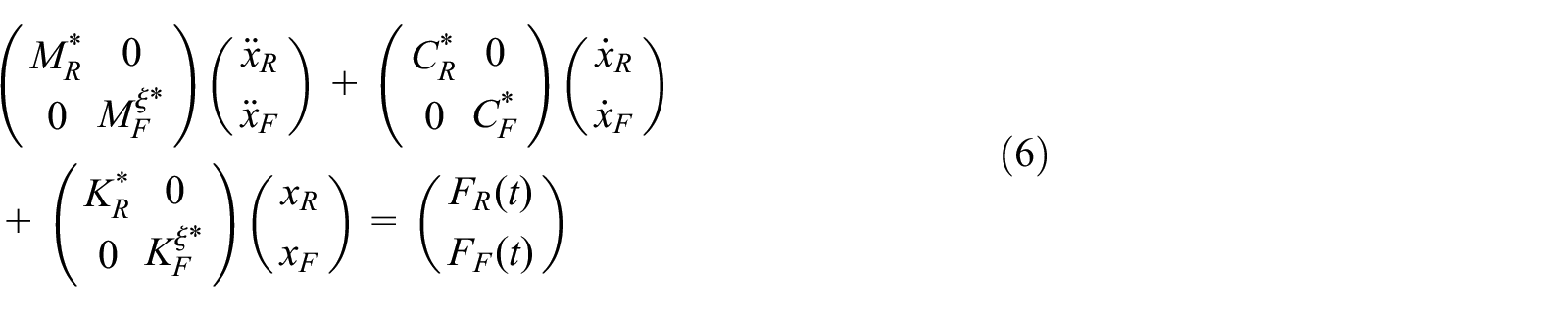
The dynamic response equation of the system is as follows:

where MR, CR, KR are the mass, damping and stiffness matrices of the Vehicle system;
For the finite element model of metro system, the influence can be ignored because of the low material damping, and its undamped free vibration equation can be expressed as

where
The local degrees of freedom of the finite element model are condensed by using the degree of freedom reduction method to generate the mass matrix and stiffness matrix with low-order generalized eigenvalues:

The reduced mass matrix and stiffness matrix are transformed by the transformation moment. The results are as follows:


where Ksm, Kss expressed s × m and s × s Stiffness matrix, s and m are the degrees of freedom of master and slave nodes in the model.
For the rigid flexible coupling model, it is also necessary to decouple the elastic part of the multi-body model, and retain the corresponding nodes and constraints. Based on the finite element model of the structure, the reduced flexible body model and other rigid body systems are assembled to regenerate the system matrix;
where
Because the damping is not considered in the original finite element model, the interface nodes are used to couple the rigid body model with large damping link. For the rigid flexible coupling model, in addition to considering the rigid body degree of freedom of the model, it is also necessary to solve the reduced degree of freedom of the main node of the model, and the modal frequency of the solution is higher than that of the rigid body model.
Longitudinal force between suspension device and vehicle body FNX, Lateral force FNY, and Vertical force FNZ are as follow:


where krX, krY, krZ are longitudinal, transverse, and vertical stiffness coefficients; crX, crY, crZ are longitudinal, transverse, and vertical damping coefficients; △Xr, △Yr, △Zr longitudinal, transverse, and vertical deflections
Load analysis under straight line conditions
Using dynamics software UM coupled dynamic model of calculation for the metro vehicle, the simulation of the vehicle when the vehicle suspension point before air conditioning A, B, C, D, simulation setting conditions for linear conditions: speed V = 160 km/s, and the simulation time t = 15 s, using UIC_good as track irregularity excitation. The maximum load and root-mean-square values of each suspension point of front and rear air conditioning are shown in Table 1. The former air conditioning is taken as an example. The position distribution of each suspension point and the load of each suspension point are shown in Figures 2 and 3, respectively. Among them, E and G are the center positions of front and rear bogies respectively; F is the center position of car body; A, B, C, and D are the suspension points of air conditioning respectively, which are distributed at 1 m on both sides of the bogie center point. The coordinates of each point are: A:(7.85, −1, 1.28), B:(7.85, 1, 1.28), C:(−7.85, 1, 1.28), D:(−7.85, −1, 1.28).
Maximum and RMS of the load at each suspension point.

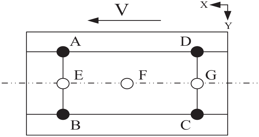
Distribution of suspension points of front and rear air conditioners.

Dynamic load of each suspension point under linear condition: (a) longitudinal dynamic load at left hanging point, (b) longitudinal dynamic load at right hanging point, (c) lateral dynamic load at left hanging point, (d) lateral dynamic load at right suspension point, (e) vertical dynamic load of left hanging, and (f) vertical dynamic load of right suspension poin.
It can be seen from the Table 1 that the maximum load in the X direction of each suspension point under the straight line condition is 251.42 N, and the maximum RMS value is 129.21 N. The maximum load in Y direction is 504.46 N, and the maximum RMS value is 164.55 N. The maximum load in the Z direction is 2599.74 N, and the maximum RMS value is 2479 N.
Load analysis under curve conditions
The simulation conditions for the curve working condition were as follows: velocity V = 160 km/s, and simulation duration t = 25s. UIC_good was adopted as the trajectory anomaly excitation. The curve radius was 1600 m, the easing curve was 170 m, the circular curve was 300 m long, and the curve was 0.13 m high. The maximum load and root-mean-square values of each suspension point of front and rear air conditioning are shown in Table 2. The load of each suspension point is shown in Figure 4.
Maximum and RMS of the load at each suspension point for the curve working condition.


Dynamic loads at each suspension point under curve conditions: (a) longitudinal dynamic load at left hanging point, (b) longitudinal dynamic load at right suspension point, (c) lateral dynamic load at left hanging point, (d) lateral dynamic load at right suspension point, (e) vertical dynamic load of left hanging point, and (f) vertical dynamic load of right suspension point.
It can be seen from the Table 2 that the maximum load in the X direction of each suspension point under linear conditions is 308.26 N, and the maximum RMS value is 148.52 N. In the Y direction, the maximum load is 665.66 N, the maximum RMS value is 234.20 N. The maximum load in the Z direction is 2697.89 N, and the maximum RMS value is 2536.96 N.
Design of suspension support
Initial design of suspension support
When the rigid connection is adopted, the air conditioner is directly connected to the car body through bolts without the need for bracket installation. The connection diagram is shown in Figure 5. For elastic suspension, additional suspension supports are required to install and secure the vibration isolation device. In order not to change the structure of the car body and air conditioning, it is necessary to design the initial structure of the suspension support and leave a certain design margin for subsequent optimization. The initial size of the suspension bracket refers to the size at the suspension point of the car body, and the 3d software SolideWorks is used for simple design.

Schematic diagram of connection between air conditioning and vehicle body suspension point.
Stiffness and strength analysis of the initial structure
After the initial structural design of the suspension support, the stiffness and strength shall be calculated to determine whether it meets the requirements. First, the 3D model of the initial structure of the suspension bracket was imported into hyperMesh, the pre-processing module of HyperWorks, to draw grids. Hexahedral grids were adopted, with a total of 20,253 cells and 22,912 nodes. For the convenience of calculation, when analyzing the stiffness and strength of the suspension support, the total longitudinal load is 400 N, the total transverse load is 800 N, and the total vertical load is 2700 N.
The material of suspension bracket is 45 steel (the steel has good toughness, plasticity, good processability, and multi-directional processing technology), the material property parameters are shown in Table 3. The boundary conditions are set as follows: the longitudinal load of bolt hole 2 and 3 are 200 N, the transverse load are 400 N, and the vertical load are 1350 N; at the same time, fix the contact place between bolt hole 1 and suspension point of the car body. The finite element model and boundary conditions are shown in Figure 6.
Material property parameter table of 45#steel.


Finite element model and boundary conditions of initial structure of suspended support.
After completing grid division, material attribute assignment and load setting, analysis, and calculation are carried out through the Optistruct solver built in HyperWorks. As shown in Figure 7, the maximum displacement of the initial structure of the suspension support under vertical load is 9.28 × 10⁻² mm, and the maximum stress is 4.6 MPa; the maximum displacement under longitudinal load is 3.5 × 10⁻² mm, and the maximum stress is 4.06 × 10⁻¹ MPa; the maximum displacement under transverse load is 4.91 × 10⁻³ mm, and the maximum stress is 6.42 × 10⁻² MPa. It can be seen that the initial structure of suspension support has a very large design margin.
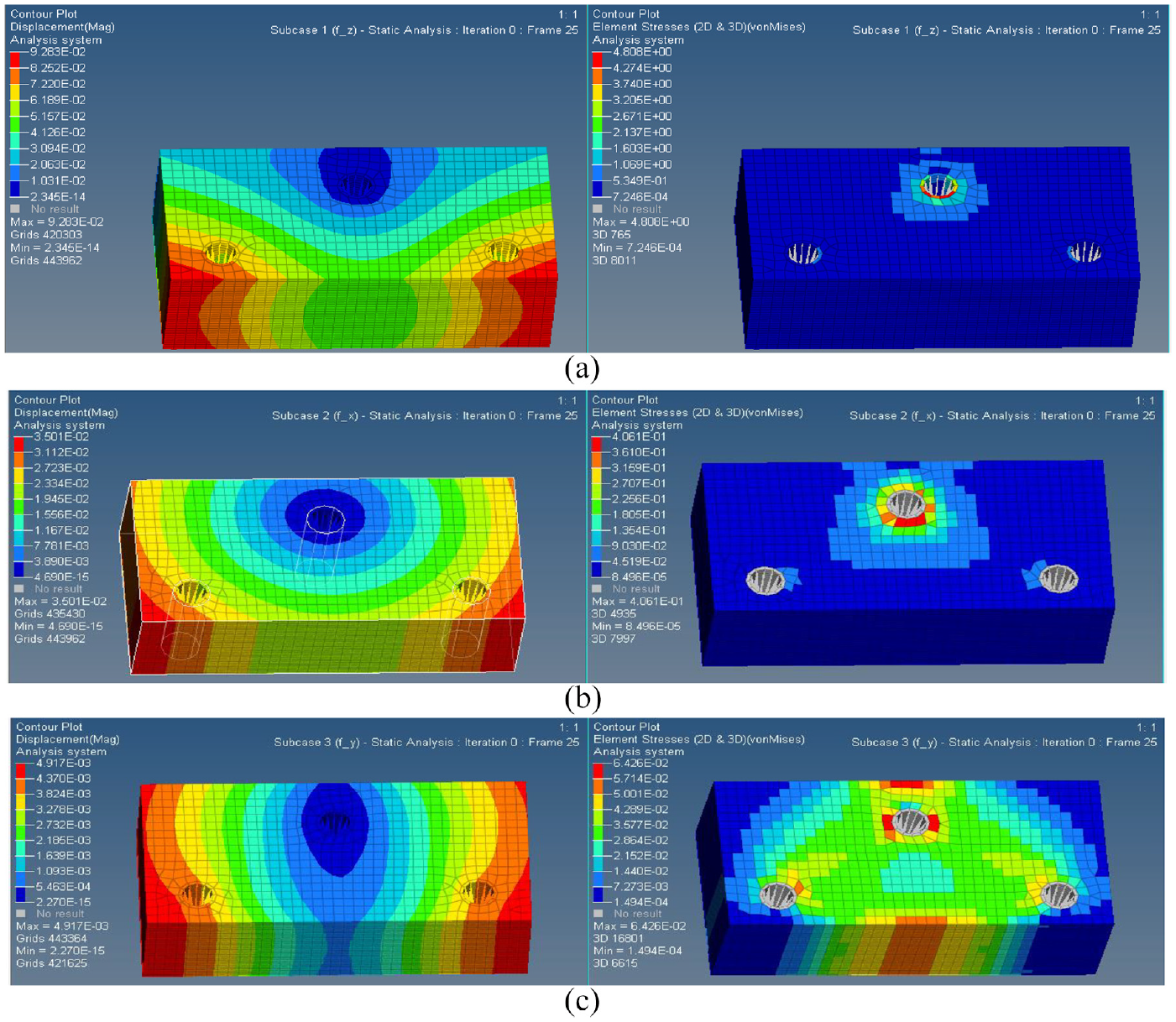
Initial structural displacement and stress diagram of suspension bracket: (a) displacement and stress under maximum vertical load, (b) displacement and stress under maximum longitudinal load, and (c) displacement and stress under maximum transverse load.
Topology optimization lightweight of suspension bracket
Through the analysis and calculation of the initial structure of the suspension support, it can be known that the initial structure of the suspension support can meet the requirements of stiffness and strength, but its overall volume and mass are not in the optimal state, which obviously violates the principle of lightweight. In order to reduce the quality of suspension support, it is necessary to optimize the initial structure of suspension support topological while ensuring its service life. When the support works for a long time, in addition to meeting the requirements of stiffness and strength under static conditions, the most important thing is to ensure the fatigue life of on-board equipment under dynamic load when the vehicle is running. According to the S-N curve of steel, if the fatigue life of the support reaches 107 stress cycles, its maximum stress is less than the fatigue limit, that is, it is in the state of theoretical infinite life.
Topology optimization lightweight related element design
The three elements of topology optimization lightweight design are constraint condition, design variable, and objective function. Constraints mean that in the process of topology optimization, the performance of the whole structure must meet certain constraints, including volume fraction, displacement, stress, life, etc. Optimization design of functions of design variables is to find a set of design variables that can make the objective function reach the best under the condition of satisfying constraints. Its mathematical model is as follows:

where x—desigvariable,
P—Number of equality constraints.
Sensitivity of structural response:

U is the displacement vector of element node; X is the design variable; G is the constraint function
Static strain energy

K is the stiffness matrix of the system; u is the node displacement vector under the load F
The variable density method is adopted in the topological optimization of the initial structure of the suspension bracket. Its essence is to give each finite element a relative density that can change between 0 and 1.1 indicates that the unit should be retained. Before topological optimization of the initial structure of the suspension bracket, its design area and non-design area shall be set. Bolt holes 1, 2, and 3 shall be set as non-design area (red area in the figure), and other units shall be set as design area, as shown in Figure 8.
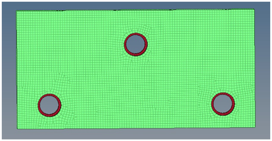
Design area and non-design area of initial structure of hanging bracket.
Topology optimization lightweight solution
In the topology optimization of the initial junction of the suspension bracket, the solid unit other than the bolt hole is taken as the optimized design space, the unit density is taken as the design variable, and the volume minimization objective function is set as follows: Since the Hyperworks software adopts the method of card management in the topology optimization calculation setting:
When setting the optimization constraints, the corresponding optimization response card must be set first. Here, the optimal response set in the topological optimization of the initial structure of the suspension support is: (1) Node displacement: the maximum displacement of the node is limited to 9.28 × 10⁻² mm, which is not more than the maximum displacement of the initial structure. It indirectly ensures that the stiffness of the optimized suspension bracket is controlled within a reasonable range; (2) Volume fraction: the ratio between the optimized volume and the volume before optimization is constrained, and is set to no more than 0.5; and (3) Fatigue life: the fatigue life of suspension support is constrained to the number of stress cycles greater than 107.
The Optistruct solver is submitted for solution after the relevant optimization setting. After 30 iterations, the model converges, and the iteration process is shown in Figure 9, as the iteration of step 1, 5, 15, 20, 25, and 30. The density threshold of the first and the fifth are 0.1, the density threshold of the fifteenth, 20, 25, and 30 are 0.3. Figure 10 shows the final optimized model under different density thresholds. It can be seen from the image that the greater the density threshold is, the less the model material will be. When the density threshold is greater than 0.6, the discontinuity of the model will appear; when the density threshold is greater than 0.7, the discontinuity of the model material will be more obvious.
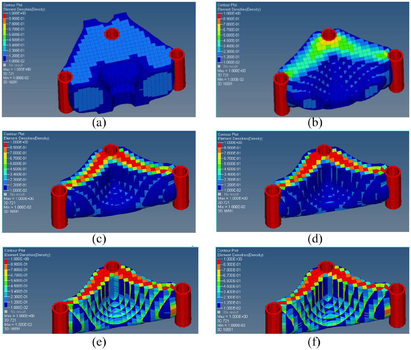
Model iteration: (a) iterative step = 1, (b) iterative step = 5, (c) iterative step = 15, (d) iterative step = 20, (e) iterative step = 25, and (f) iterative step = 30.

Final iteration model image under different density thresholds: (a) density threshold = 0, (b) density threshold = 0.1, (c) density threshold = 0.2, (d) density threshold = 0.3, (e) density threshold = 0.4, (f) density threshold = 0.5, (g) density threshold = 0.6, and (h) density threshold = 0.7.
After topological optimization of the initial structure of the suspension bracket is completed, it needs to be analyzed and calculated. First, the optimized reconstruction model is derived by using OSSmooth component of Optistruct, and the density threshold during reconstruction is 0.3, as shown in Figure 11. As can be seen from the figure, the geometry of the model is very irregular and difficult to manufacture, so the design needs to be carried out again according to the stress neutrogram and the derived reconstruction model.

Finite element structure after suspension bracket optimization.
Verification of optimization results
The 3d surface shape of the optimized irregular model is generated in the Hypermesh, as shown in Figure 12. Since there are many depressions and ridges on the surface of the optimized model, and there are discontinuations between surfaces, it is difficult to repair directly on the basis of the original model after importing into the 3D software Solideworks, and it needs to be redesigned. In order to consider the actual manufacturing, the design should reduce the protrusions and depressions on the support surface, and keep the shape as simple as possible. The redesigned bracket geometry is shown in Figure 13.

3D diagram of optimized hanging bracket structure.

3D view of the redesigned hanging bracket.
After the design of 3D structure is completed, 3D graphics are imported into HyperMesh software in IGES format, and then meshed and given material properties. The pre-processing process is basically the same as the original structure of suspension bracket. The model after preprocessing is shown in Figure 14. There are 52,550 units and 57,304 nodes in the model.

Finite element model of the redesigned suspension bracket.
After the pretreatment of the model, two conditions of dynamic analysis and static analysis were set. The fatigue characteristic data of 45 steel are shown in Figure 15. Among them, the stiffness and strength of the model were mainly analyzed in the static condition, while the fatigue life of the model was mainly analyzed in the dynamic condition, namely the fatigue condition. Submit Optist, as shown in Figure 16.

N-S diagram of fatigue characteristics of 45# steel.

Cloud diagram of stress, strain and fatigue life of suspension bracket: (a) displacement and stress under maximum longitudinal load. (b) displacement and stress under maximum transverse load, (c) displacement and stress under maximum vertical load, and (d) damage and life under dynamic load.
According to the calculation results, under the maximum longitudinal load, the maximum displacement of the support is 7.118 × 10⁻⁴ mm and the maximum stress is 0.8365 MPa. Under the maximum transverse load, the maximum displacement of the support is 3.892 × 10⁻⁴ mm and the maximum stress is 0.5673 MPa. Under the maximum vertical load, the maximum displacement of the support is 5.442 × 10⁻⁵ mm and the maximum stress is 2.41 MPa. Under dynamic load, the minimum fatigue life of the support is 5 × 10¹⁹ times of stress cycle, which is far greater than the bottom line of 107 times of infinite life, meeting the design requirements.
Conclusion
In this paper, the rigid and flexible coupling dynamic model of metro is firstly calculated, and UIC_good is used as the track unevenness excitation to simulate the stress of the suspension point of the air conditioning system of the vehicle body when the vehicle is running. The initial structure design of the suspension support is carried out. The stress of the air conditioning suspension point obtained previously is taken as the load input to analyze the stiffness and strength of the initial structure of the suspension support. Then, variable density method (SIMP) is adopted to optimize the suspension bracket topology by taking fatigue life as topology constraint. The results show that:
Under linear conditions, the maximum loads at each suspension point in the X, Y, and Z directions are 252.13 N, 517.77 N, and 2599.74 N, respectively, and the maximum RMS values are 128.66 N, 164.55 N, and 2483.87 N, respectively. Under the curve conditions, the maximum loads in the X, Y, and Z directions of each suspension point are 327.92 N, 665.666 N, and 2697.89 N, and the maximum RMS values are 155.64 N, 248.00 N, and 2504.351 N, respectively. The load and root mean square value under curve condition are larger than those under straight line condition. Therefore, when analyzing the suspension characteristics of urban rail train body, we should pay attention to the parameter characteristics of suspension parameters under curve condition.
The maximum displacement of the initial structure of the suspension bracket under longitudinal load is 3.5 × 10⁻² mm, and the maximum stress is 4.06 × 10⁻¹ MPa; the maximum displacement under transverse load is 4.91 × 10⁻³ mm, and the maximum stress is 6.42 × 10⁻² MPa; the maximum displacement under vertical load is 9.28 × 10⁻² mm, and the maximum stress is 4.6 MPa. It can be seen that the maximum displacement and maximum stress of the suspension support are 38% and 69% of the longitudinal load and 69% of the longitudinal load respectively; the maximum stress is 10% and 0.13% of the longitudinal load respectively; therefore, it can be found that the main stress and deformation direction of the suspension support is Z direction, so the stress and deformation in Z direction should be paid attention to in the design process of suspension support.
After the topological optimization of the suspension support, the maximum displacement of the support under the maximum vertical, horizontal and vertical loads was 7.118 × 10⁻⁴ mm, 3.892 × 10⁻⁴ mm, and 5.442 × 10⁻⁵ mm, respectively, which was reduced by 80%, 93%, and 99% compared with the initial structural model. The maximum stress of the support is 0.8365 MPa, 0.5673 MPa, and 2.41 MPa, respectively, and the maximum stress under vertical load is reduced by 50%. It can be seen that the topology optimization of the suspension bracket can reduce the stress in Z direction to half of the original value under the condition of satisfying the lightweight principle and satisfying the optimal mass and volume; meanwhile, under the dynamic load, the minimum fatigue life of the bracket is 5 × 10¹⁹ times of stress cycle, which is far greater than the infinite life bottom line of 107 times, It can be seen that the suspension bracket in this paper after topology optimization lightweight meet the design requirements.
Footnotes
Declaration of conflicting interests
The author(s) declared no potential conflicts of interest with respect to the research, authorship, and/or publication of this article.
Funding
The author(s) received no financial support for the research, authorship, and/or publication of this article.