
Abstract
This paper presents a new type of crawler guide rail dual drive micro feed servo system based on “crawler type” guide rail. Through the innovative design of the crawler guide rail and the change of the working mode, the table, and the crawler type movable rail are relatively static, and the influence of nonlinear friction in low-speed micro feed is eliminated, so that the system can have a lower stable speed limit and realize accurate micro feed control. The Euler-Bernoulli beam element with axial and torsional degrees of freedom is used to describe the axial and torsional vibrations of the ball screw, and the lumped parameter method is used to analyze other parts of the feed system, and the electromechanical coupling dynamic model considering the nonlinear friction is established. The transfer function block diagram is used to characterize the motion relationship of the crawler guide rail dual drive servo feed system. The response difference between the screw single drive system and the new crawler guide rail dual drive system is analyzed by simulation when feeding at constant or variable speed, and the influence of different feed speed on the dynamic performance of the system. The results show that the low speed micro feed performance of the new crawler guide rail dual drive servo system is obviously better than that of the screw single drive system under the condition of constant speed or variable speed.
Keywords
Introduction
One of the key technical bottlenecks to realize ultra-precision machining is how to obtain accurate, stable, and reliable micro displacement by the tool or work piece during machining process. 1 Although the static reverse clearance can be reduced or even eliminated by proper preloading method, 2 the nonlinear motion caused by uncertain factors such as friction cannot be eliminated, and the nonlinear influence of friction caused by linear motion is much greater than that caused by rotating parts. 3 Therefore, in CNC machine tools, the linear motion of the table relative to the guide rail has become the main factor limiting the improvement of feed accuracy. However, the traditional CNC machine tools mostly use fixed linear guideway. When the table is micro fed, the relative moving speed is very low, and the table will crawl, which will affect the positioning accuracy and processing performance.
Based on the principle of motion synthesis and modern servo drive technology, this paper innovatively proposes a new crawler guide rail dual drive micro feed servo system. By “a ball screw driven by servo motor and drive the table linear motion” and “a servo motor drive the crawler guide rail movement” of the two quasi equal (equal instantaneous speed and same direction) superposition of macroscopic movement, the crawling phenomenon caused by nonlinear friction when the traditional fixed guide rail and the table move at a relatively low speed is avoided, achieving high precision micro feed control, fundamentally eliminate the linear motion of the crawl.
The fairly mature approach for modeling the screw drive feed system is to use the lumped mass method to model the elastic screw drive system,4–10 Feng 4 constructed a preload-adjustable ball screw feed drive system based on a modified double nut structure, meanwhile, proposed a lumped dynamic model to study the preload variation of the system. Liu 5 modeled the elastic ball screw drives system through lumped mass method, and calculated the frequency response characteristic by Lagrange energy method and state space analysis. Jiang 6 built a dynamic model of linear guideway joint with ball screw by means of the linear stiffness of linear rolling guideway and the axial stiffness of ball screw and angular contact ball bearing. Mo 8 established the dynamic model for the herringbone planetary gear transmission system by the lumped parameter method based on the system dynamics and the Lagrange equation, and studied the impact of the support stiffness and the torsional stiffness on dynamic characteristics. Wu 9 proposed a hybrid field model integrating complex permeance method and lumped parameter magnetic circuit model in this paper for predicting the on-load magnetic field considering nonlinearity effect of stator lamination. Xi 10 developed a multimass model of the ball screw system and validated by experimental data, which is used to simulate the dynamic behavior of the machine axis dependent on wear. However, the above research results are all aimed at the screw single drive feed system, and the dynamic model of the dual drive feed system is not established.
There are many achievements in impact on the system caused by the nonlinear factors,11–15 such as the stiffness of the transmission system, servo control parameters, and effects on the system of the friction. Liu 11 established a comprehensive mechanical model considering friction and clearance, and studied the influence of friction and clearance nonlinearity on the output of table under the condition of low speed feed. Dong 12 used the lumped parameter method to describe the AC servo drive subsystem and other parts of the feed system, and established a flexible feed system model including friction, clearance nonlinearity, and external cutting force interference. Wu 13 established the multi degree of freedom mechanical model and mathematical model of the feed servo system, then studied the influence of various stiffness changes on the output of the table under low-speed feed. Aiming at problems of vibration, impact, and noise. Li 15 studied the nonlinear dynamic characteristics of servo hydraulic cylinder by using combination of theoretical derivation and simulation experiment methods. The above results do not study the influence of friction on the variable speed of feed system.
There are some scholars who have studied and analyzed the dual servo system through establishing mathematical model.16–19 Hsieh 16 presented a synchronous control scheme and system modeling technique for a single-axis stage driven by dual parallel ball screws/servo motors. Kim 17 presented a new design for the rotational transmission mechanism with dual four-bar linkages for the non-servo motor type automatic tool changer. Zhu 18 established the electromechanical model of the fast tool servo system by combining the piezoelectric actuator and the flexure hinge mechanism for the formulation of the control methodology. Liu 19 proposed a novel high capacity servo press system with two servo motor inputs and high ratio force amplifier mechanism for metal forming. The above results do not study the transmission performance of the crawler guide rail dual drive servo system.
In this paper, considering the influence of nonlinear friction, a multi degree of freedom mathematical model of the closed-loop control machine tool feed servo system is established, which comprehensively considers the axial and torsional stiffness of the screw, the axial stiffness of the bearing, and the transmission stiffness of crawler guide rail. The influence of nonlinear friction on the dynamic response characteristics of crawler guide rail dual drive servo system and screw single drive system in low-speed micro feed is analyzed by numerical calculation.
Configuration of the crawler guide rail dual drive system
Figure 1 shows the configuration of the crawler guide rail dual drive feed system, components as follows: 1.foundation, 2.screw servo motor “A,” 3.coupling, 4.screw fixed end mounting, 5.ball screw, 6.nut, 7.nut mounting, 8.table, 9.screw support end mounting, 10.crawler guide rail wheel, 11.crawler guide rail, 12.slider, 13.crawler guide rail servo motor “B.”

Crawler guide rail dual drive precision transmission mechanism.
In this paper, a dual drive micro feed servo system with “crawler type” guide rail is provided, which makes the table and “crawler type” movable guide rail relatively static, eliminates the influence of nonlinear friction in low-speed micro feed, and enables the system to have lower stable speed limit and realize accurate micro feed control. The screw servo motor “A” drives the ball screw and drives the straight line movement of the table. The crawler guide rail motor “B” drives the crawler type guide rail movement. According to the given motion requirements of the table, the instructions of servo motor “A” and servo motor “B” are assigned according to the specific algorithm to coordinate and control the respective movement of the screw and crawler guide rail.
The table moves along the X-axis in a straight line driven by the servo motor “A,” and the speed is represented by V1; Driven by servo motor “B” alone, the “crawler type” guide rail will also move in a straight line along the X-axis, and the speed is represented by V2. Finally, by controlling, the instantaneous velocity of the table and crawler guide rail is equal and the direction is the same, so as to ensure the instantaneous synchronization between the table and the “crawler type” movable guide rail, that is, the relative speed of the table to the crawler guide rail is “V1 − V2 = 0.” In this way, the crawling phenomenon of the table in low-speed micro feed can be eliminated, and the high-resolution micro feed motion which is difficult to obtain by the conventional screw single drive servo system can be obtained.
Dynamic model of the crawler guide rail dual drive system
Mechanical model
The crawler guide rail dual drive servo feed system is based on the principle of motion synthesis and servo drive technology, which is obtained by the differential speed of screw single drive and “crawler guide rail” single drive on the same axis. Therefore, it is necessary to establish the mathematical models of screw single drive system and crawler guide rail single drive system respectively.
When modeling the crawler guide rail drive system, the following assumptions are made: (1) the stiffness calculations are made for the center position of the table; (2) The rigid connection between the nut mounting and the table ignores the deformation of the nut mounting; (3) crawler guide rail motor and drive wheel are rigid connection, no torsion angle deviation; (4) ignore the angle deviation between the screw servo motor and the ball screw.
The configuration of the crawler guide rail dual drive feed system shown in Figure 1 is expressed as the mechanical model of elastic structure system established by lumped parameter method as shown in Figures 2 to 5.
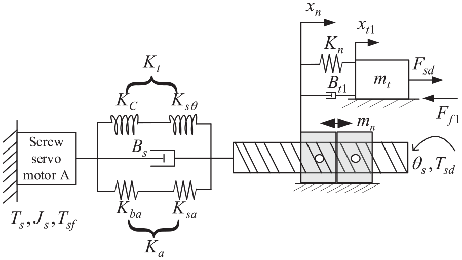
Mechanical model of screw single drive system.
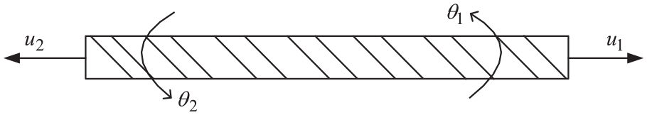
Euler Bernoulli beam element with axial and torsional degrees of freedom.

Mechanical model of crawler guide rail single drive system.
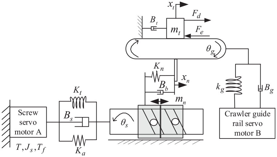
Mechanical model of crawler guide rail dual drive system.
Ball screw single drive system analysis
As shown in Figure 2, the mechanical model of the screw single drive system is shown. Under the condition of screw single drive, the screw motor “A” directly drives the screw to rotate through the coupling, which is converted into the linear motion of the table. The equations of motion for the screw single drive system are11,12:


Where
As shown in Figure 3, Euler Bernoulli beam model with axial and torsional degrees of freedom is adopted,20–23 and the degree of freedom of ball screw beam element includes axial displacement

According to the stiffness and mass matrix of the basic beam element, the mass matrix


Crawler guide rail single drive system analysis
As shown in Figure 4, the mechanical model of the crawler guide rail single drive system is shown. Under the crawler guide rail single drive condition, the servo motor “B” directly drives the “crawler type” guide rail to rotate through the transmission wheel, which is converted into the linear motion of the guide rail. The equations of motion for the crawler guide rail single drive system are:


Where
Dual drive system analysis
The new transmission system is driven by the screw motor and the crawler guide rail motor, and the instantaneous speed and displacement between the table and the “crawler type” guide rail are kept equal through control, so as to realize the high-precision micro displacement of the table, that is, the following relationship needs to be satisfied:

Figure 5 shows the mechanical model of crawler guide rail dual drive system. In the case of crawler guide rail dual drive, there is no nonlinear friction force between the table and the “crawler type” guide rail because the relative speed of the two is zero. The equations of motion for the crawler guide rail dual drive system are 14 :


Where
In order to make the table have the same motion parameters under different driving modes, the integrated transmission stiffness of the two single drive and dual drive systems should be consistent. Therefore, the comprehensive stiffness of the two single drive and dual drive systems should be equal, that is
Friction model
The main factor that affect the dynamic performance of the system is the friction nonlinear, therefore, considering the nonlinear response of the friction, the electromechanical coupling dynamic analysis of crawler guide rail dual drive system is carried out.
The equivalent coulomb friction torque of the servo motor is given by

To establish friction model between guideway and table, LuGre model proposed by Canudas 24 is used to solve friction on the table, this model can accurately describe static and dynamic characteristics of various friction, which include pre-sliding displacement, friction lag, change of static friction, creeping and Stribeck effect. It can be seen from Figure 6, the maximum static friction force to the sliding friction presents a continuous change of a negative damping characteristics.

Stribeck curve.
Supposing state quantisty


Where
When the system is in steady state, then

AC servo motor model
Servo motor has the advantages of high precision, fast response, etc., for AC servo system PMSM after appropriate simplification the command signal through the position, velocity, and current feedback gain obtain the output torque. The current equation is given by13–14

Where
The input voltage to the servo motor

Crawler guide rail dual drive system block diagram model
The mechanical equation of the crawler guide rail dual drive servo system is transformed into the transfer function block diagram as shown in Figure 7. The electromechanical coupling dynamic comprehensive model of the dual drive feed system is characterized, and the effect of the nonlinear friction on the system is considered.
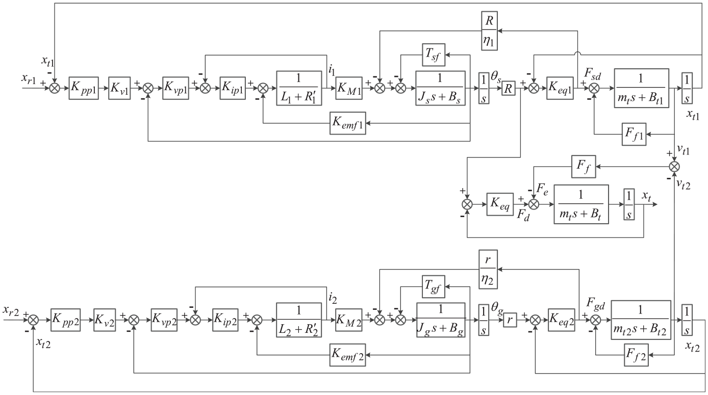
Transfer function block diagram of the crawler guide rail dual drive system.
Simulation and analysis
The parameters used in the model are obtained from manufacturers’ catalogs, approximated from prior knowledge, or calculated from computer aided design models of the drive components, as listed in Table 1.
Parameters and related values used in modeling the crawler guide rail dual drive system.

Critical creeping speed analysis
After repeated calculation on system parameters, the critical creeping speed of table with screw single drive system is obtained and its value approximate 2.5 mm/s. As shown in Figures 8 to 11, the simulation results of the screw single drive system at feed rates of 2.3, 2.4, 2.5, and 2.6 mm/s are shown respectively. When the table reaches the steady state, there is no obvious fluctuation in the minimum feed speed, that is, it is considered to reach the critical creeping speed. In order to explore the lowest steady-state feed speed of screw single drive system, the author analyzes four magnitudes (2.3, 2.4, 2.5, and 2.6 mm/s) by simulation. It can be seen from Figures 8 and 9 that when the feed speed of the table are 2.4 and 2.5 mm/s respectively, there are obvious vibration and limit cycle phenomena in the output speed curve of the screw single system. However, it can be seen from Figures 10 and 11 that when the feed speed of the table are 2.5 and 2.6 mm/s respectively, the output speed curve of the screw single system reaches the steady state after about 2 s of adjustment. It can be considered that the critical crawling speed of the screw single drive system is 2.5 mm/s.

Screw single drive feed speed (2.3 mm/s).

Screw single drive feed speed (2.4 mm/s).

Screw single drive feed speed (2.5 mm/s).
Screw single drive feed speed (2.6 mm/s).
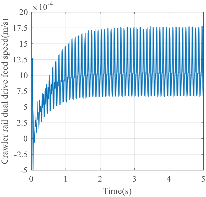
To find the critical creeping speed of the crawler guide rail dual drive system, two constant rates are input to screw motor and crawler guide rail motor respectively, through the control system to ensure the table and “crawler type” guide rail instantaneous synchronization. Many simulations are carried under the same parameters, the critical creeping speed of crawler guide rail dual drive system approximately reaches to 1.2 mm/s. As shown in Figures 12 to 15, the simulation results of the crawler guide rail dual drive system at feed rates of 1.1, 1.2, 1.3, and 1.4 mm/s are shown respectively.
Crawler rail dual drive feed speed (1.1 mm/s).
Crawler rail dual drive feed speed (1.2 mm/s).

Crawler rail dual drive feed speed (1.3 mm/s).

Crawler rail dual drive feed speed (1.4 mm/s).
As shown in Figure 12, when the feed speed of the table is lower than the critical creeping speed, the feed characteristics of the system show oscillation and limit cycle phenomenon. However, as shown in Figure 13, when the feed speed of the table is greater than the critical creeping speed, the system can reach the steady state after a certain period of adjustment (as the feed speed is 1.2 mm/s, the adjustment time is about 2.5 s), and the crawler guide rail dual drive system shows superior feed characteristics at low speed.
It can be seen from Figure 12 that when the feed speed of the crawler guide rail dual drive system is 1.1 mm/s, there is obvious vibration and limit cycle phenomena in the output speed curve of the system. However, it can be seen from Figures 13 to 15 that when the feed speed of the crawler guide rail dual drive system are 1.2, 1.3, and 1.4 mm/s respectively, the output speed curve of the system reaches the steady state after adjustment. It can be considered that the critical crawling speed of the crawler guide rail dual drive system is 1.2 mm/s. After repeated calculation on system parameters, it is found that the above four magnitudes (1.1, 1.2, 1.3, and 1.4 mm/s) are the closest to the critical creeping speed, so the author chooses the above four magnitudes to explore the critical creeping speed of the crawler guide rail dual drive system.
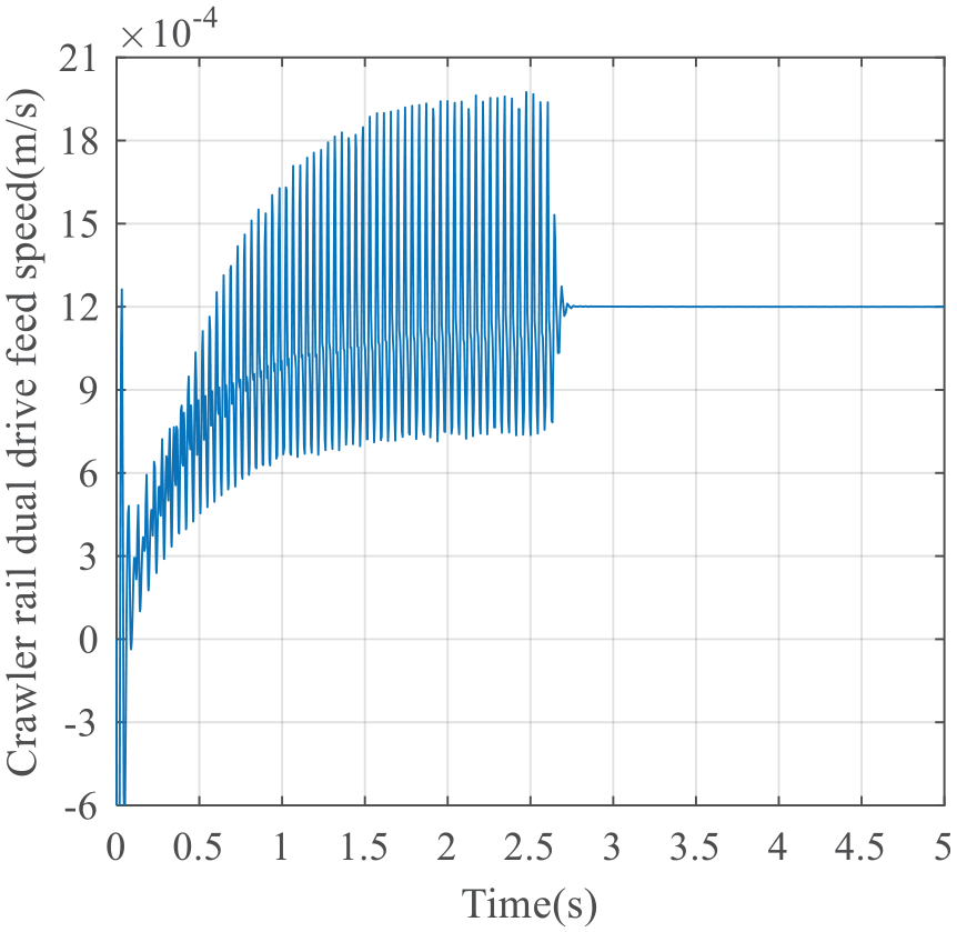
It can be seen from Figures 8 to 15 that under the same parameters, the critical creeping speed of crawler guide rail dual drive system is lower than that of screw single drive system. Further study the output result of table speed when the constant speed feed of crawler guide rail dual drive system is 2.5 mm/s, and the simulation result is shown in Figure 16.

Crawler rail dual drive feed speed (2.5 mm/s).
From the Figures 8 to 16, it is can be found that the crawler guide rail dual drive system shares a smaller critical creeping speed, so it can offer a relatively stable and normal working condition to the table when the screw single drive system has reached its critical state. In addition, The dynamic response characteristics of crawler guide rail dual drive system is better than that of the screw single drive system. Therefore, the low-speed stability of crawler guide rail dual drive system is better than that of screw single drive system.
Constant speed analysis
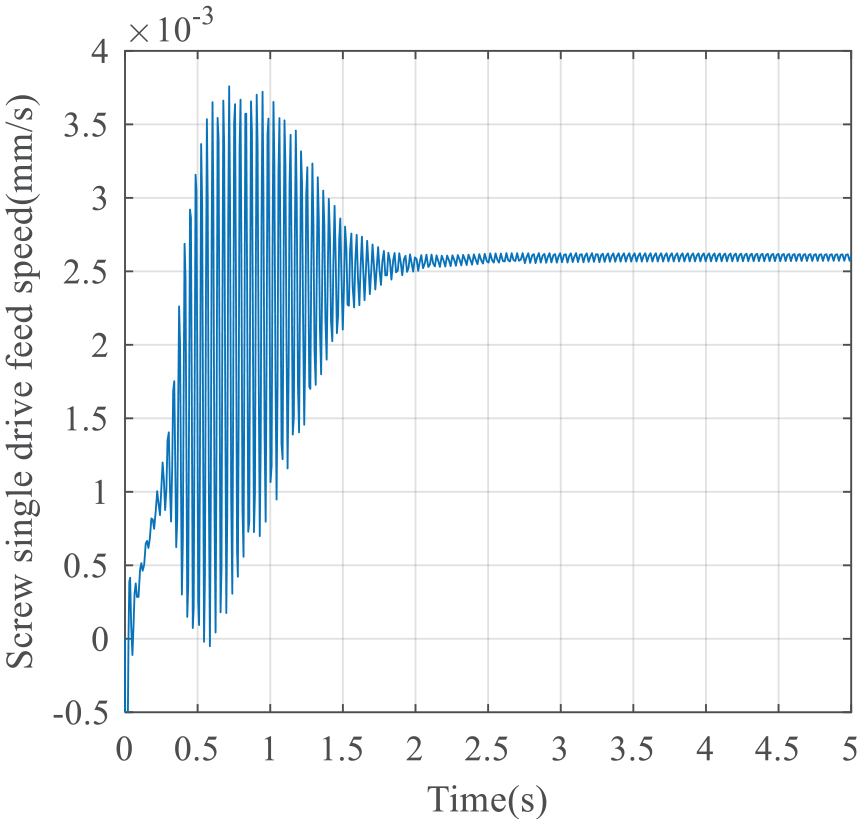
Through analysis, it is found that the critical creeping speed of the table with crawler guide rail dual drive system is close to 1.2 mm/s, while that of screw single drive system with the same parameters is 2.5 mm/s, further study that what constant feed rate is maintained, the output speed of the table will not be over modulation under the two driving conditions. After many times of simulation calculation, as shown in Figure 17, when the feed rate of crawler guide rail dual drive system is 1.8 mm/s, the output speed of the table will not produce obvious over modulation. As shown in Figure 18, when the feed rate of the screw single drive system is 3.8 mm/s, the output speed of the table will not be over modulation.
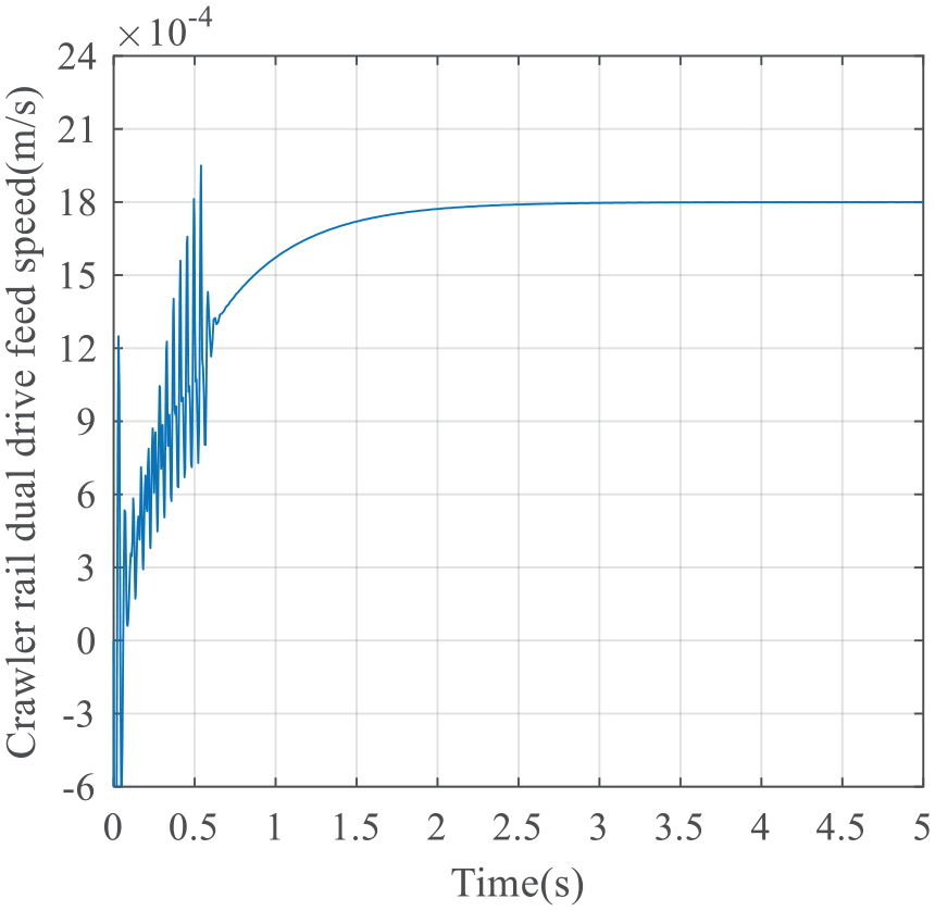
Crawler rail dual drive feed speed (1.8 mm/s).
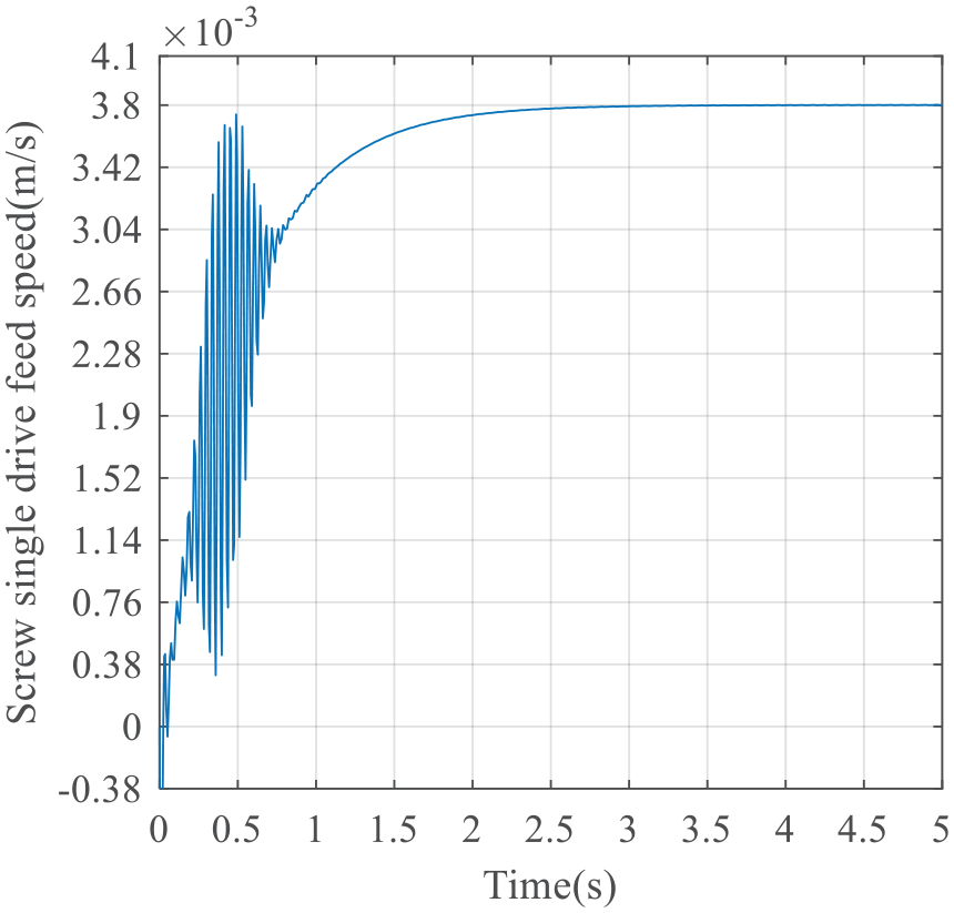
Screw single drive feed speed (3.8 mm/s).
When the feed rate of the crawler guide rail dual drive system is 3.8 mm/s, the difference of the output speed fluctuation of the table under two driving conditions is analyzed. As shown in Figure 19, the simulation result when the feed speed of the crawler guide rail dual drive system is 3.8 mm/s.

Crawler rail dual drive feed speed (3.8 mm/s).
From Figures 17 to 19, the conclusion is that crawler guide rail dual drive system has a relatively small fluctuation than screw single drive system when both of them are under low speed. Furthermore, from the point of view of dynamics, the crawler guide rail dual drive system has better low-speed micro feed performance and fast response than the screw single drive system. At the same time, it can be concluded from Figures 17 to 19 that with the increase of the command speed, the feed characteristics of the crawler guide rail dual drive system and the screw single drive system tend to be consistent at high speed.
Variable speed analysis
The above analysis is carried out when the speed is constant, now this paper studies the difference of the output speed of the table between the crawler guide rail dual drive system and the screw single drive system when the speed is variable. When the crawler guide rail dual drive, the sinusoidal speeds are input to the screw motor and the crawler guide rail motor respectively, so as to ensure the instantaneous synchronization of the table and the “crawler type” guide rail through the control system.
When the table of crawler guide rail dual drive system feeds at the sinusoidal speeds with maximum amplitude of 2.5 and 3.8 mm/s, the simulation results of system response are shown in Figures 20 and 21 respectively. When the table of screw single drive system feeds at the sinusoidal speeds with maximum amplitude of 2.5 and 3.8 mm/s, the simulation results of system response are shown in Figures 22 and 23 respectively.

Dual drive sinusoidal feed (Am 2.5 mm/s).

Dual drive sinusoidal feed (Am 3.8 mm/s).

Single drive sinusoidal feed (Am 2.5 mm/s).

Single drive sinusoidal feed (Am 3.8 mm/s).
Comparing Figures 20 and 22, as well as Figures 21 and 23, it can be seen that the crawler guide rail dual drive system has a relatively small fluctuation than the screw single drive system when both of them set a low sinusoidal speed, which shows the crawler guide rail dual drive system has better variable speed micro-feed performance than that of the screw single drive system. It can also be seen from Figures 20 to 23 that when the speed crosses zero point, obvious speed fluctuation occurs in both the crawler guide rail dual drive system and the screw single drive system, but the speed fluctuation of the former is obviously smaller than that of the latter.
Conclusions
This new type of the crawler guide rail dual drive micro feed mechanism can overcome the disadvantages for the current CNC machine tool unit axis, which is difficult to achieve accurate and uniform micro-feed motion, because of the nonlinear creeping influence. Meanwhile, compared with those micro-feed mechanisms commonly used currently based on the piezoelectric effect, the electric (magnetic) effect, and the thermoelastic effect methods, this new crawler guide rail dual drive system also has the advantages of large stroke, high rigidity, high precision, high load, and easy to control. Therefore, the research obviously has a far-reaching significance on CNC equipment new concept design, processing performance enhancement, and ultra-precision machining technology development.
This paper designs a new type of crawler guide rail dual drive system and establishes the electromechanical coupling dynamic model of the system with lumped parameter method. Besides, considering instantaneous synchronous control, it also establishes the transfer function block diagram for the simulation of system models including mechanical model, friction model, and motor model.
According to the results of numerical simulation, it can be found the crawler guide rail dual drive system has a lower critical creeping speed in comparison with screw single drive system. By analyzing the output speed of the table under the constant speed condition and the variable speed condition of two types of drive, the conclusions are that the crawler guide rail dual drive system has better micro-feed performance at low speed and quicker responsiveness than screw single drive system.
The results of theoretical calculation and numerical analysis are basically consistent with the actual engineering phenomenon, which shows that the established models are reasonable. The establishing of the system model lays the foundation of the research in the design of controller.
The potential applications of the crawler guide rail dual drive servo system and the results of numerical analysis can be applied to advanced technology fields such as robotics, suspensions, powertrain, national defense, integrated electronics, optoelectronics, medicine, and genetic engineering, so that the new system can have a lower stable speed limit and achieve precise micro-feed control.
Footnotes
Declaration of conflicting interests
The author(s) declared no potential conflicts of interest with respect to the research, authorship, and/or publication of this article.
Funding
The author(s) disclosed receipt of the following financial support for the research, authorship, and/or publication of this article: This study is supported by the Natural Science Foundation of Shandong Province, China (Grant No. ZR2019PEE006).