
Abstract
This article presents a new micro-feed mechanism, whose main transmission component is the nut–rotary ball screw pair. The screw and nut are driven by two motors, and they rotate in the same direction, with their movements enabling micro-feeding. The main contribution of the micro-feed mechanism is to avoid the inevitable low-speed nonlinear creeping phenomenon caused by the inherent properties of traditional electromechanical servo system structure, thus realizing high precision micro-feed. In this study, the motion state of the working ball is analyzed using the principle of differential geometry, the friction at the contact points is calculated, the balance equation for force and moment is established, the influences of the screw and nut on the kinematic parameters of the ball at different velocities and the differences in the motion states of the ball in different drive modes are studied, and the mechanical efficiency of the dual-driven ball screw mechanism is calculated. The potential applications of the new micro-feed mechanism and the results of numerical analysis can be applied to advanced technology fields such as robotics, suspensions, powertrain, national defense, integrated electronics, optoelectronics, medicine, and genetic engineering, so that the new system can have a lower stable speed limit and achieve precise micro-feed control.
Keywords
Introduction
In this article, we propose a dual-servo micro-feed mechanism based on the motion synthesis principle. The motor-driven ball screw and motor-driven ball nut of two quasi-equal areas can realize a micro-feed mechanism. The rotary nut and ball screw pair is the key component of movement and force transmission, and their dynamic performance directly determines the precision of the micro-feed mechanism; therefore, the kinematic characteristics of the dual-driven ball screw mechanism should be investigated.
Significant progress has been made in the research on the kinematics of single-driven ball screw feed mechanisms. The kinematic behaviors of ball screws and ball bearings are similar; thus, the analysis method applied to ball bearings can be used to study the kinematic characteristics of a dual-driven ball screw mechanism. Harris1,2 analyzed the sliding characteristics between the ball and the inner ring roller, derived the contact stress on the rolling surface, and analyzed the failure mode of the bearing. Lin et al. 3 presented a theoretical analysis method to analyze the kinematic characteristics of a ball screw mechanism to explain the movement and contact patterns of the ball with the contacting elements using the established equations, and they found that a sliding phenomenon always existed in the elliptical contact area of the balls and screw or nut. Lin et al. 4 employed three methods to calculate the mechanical transmission efficiency of a system and derived an approximate closed-form solution for the mechanical efficiency of ball screw kinematics, and this solution was used to optimize the mechanism. Huang and Ravani 5 presented an algorithm using a medial axis transformation to analyze the contact stresses in the ball–nut and ball–screw contact areas. Wei and Lin 6 analyzed the kinematic characteristics of a single-driven ball screw mechanism by considering the change in the elastic deformation and contact angle. Wei et al. 7 analyzed the kinematics of the ball screw mechanism with pre-tightening force when the oil lubrication is considered, and the calculation results of the theoretical mechanical transmission efficiency were verified by experimental data. Wei and Lai 8 analyzed the kinematic state of the ball screw mechanism with pre-tightening force of the single screw nut and double roller operating at high rotational velocities. Wei et al. 9 proposed a novel two-body wear model combined with motion theory to describe the variation in the axial wear depth with respect to the operating level. On the basis of Jones’ channel control theory, 10 Yoshida et al. 11 established an analysis method to determine the movement state and load distribution of the ball and studied the effect of the ball screw geometry and different conditions on the ball movement state. Hu et al. 12 used a homogeneous transformation matrix to establish a kinematic model for a basic single-driven ball screw mechanism and analyzed the kinematic characteristics and slide–roll ratios at the contact points of the raceways. Nakashima et al. 13 analyzed the influence of the ball screw pair of a double nut on the elastic deformation of the screw in an ultra-precision positioning test table when the preload was changed. Mu and Feng 14 analyzed the kinematic parameters of a nut-driven ball screw mechanism, studied the problem of isothermal elastohydrodynamic lubrication in elliptical contacts, and used a multigrid solver to derive the numerical solution for the parameters. Xu et al. 15 presented a crawling analysis model based on rolling contact theory to obtain the frictional force of a ball screw mechanism and studied the effects of crawling parameters on the distribution of friction resistance in a ball screw mechanism. Considering the influence of frictional force and wear during operation, Zou and Wang 16 studied the change in the contact stiffness of linear rolling guides and established the initial and final models for contact stiffness. Wei Li and Jorge Angeles 17 developed a ball screw driving system of 2 DoF; the kinematic analysis, undertaken with a geometrical method based on screw theory, leads to two Jacobian matrices, whose singularity conditions are investigated.
All the aforementioned studies focus on single-driven ball screw mechanisms. In this study, in order to overcome the disadvantage that the current typical single-drive servo system of screw has difficulty in achieving precise micro-feed because of the low-speed creeping phenomenon, a new type of differential micro-feed mechanism based on nut rotating ball screw pair is proposed. The change in drive mode leads to a change in the kinematic state of the ball and consequently affects the transmission precision. In this study, a kinematic analysis of the dual-driven ball screw mechanism is performed, and the movement track of the ball and the relative velocity at the contact point are obtained. Given that friction is the main factor affecting the positioning accuracy of the mechanism, the balance equations for force and torque are established by calculating the frictional force at the contact point. Numerical analysis is employed to solve for the kinematic and dynamic parameters of the dual-driven system and establish the expressions for mechanical efficiency and other performance parameters. In this article, the object to be analyzed is the rotary ball screw pair of the right-hand screw nut.
Configuration of the dual-driven mechanism
Figure 1 shows the mechanical components of the dual ball screw mechanism.

Mechanical components of the dual ball screw mechanism.
The dual-driven system is composed of a nut and rotary ball screw pair, which is connected to the screw motor shaft and is restricted in the axial and radial directions by the angular contact ball bearing on the motor side. The nut and rotary ball screw pair are each supported by a radial ball bearing to provide axial freedom. The rotations of the nut and the rotary ball screw pair are converted into the linear motion of the table, which is braced by two parallel rolling guides.
Theoretical analysis of the dual-driven ball
For the investigation on the kinematic characteristics of the dual-driven ball screw mechanism, four coordinate frames (Figure 2) are established to describe the movement of the ball. Given that the angular velocities of the spin and revolution of the ball change with variation in the contact point, the right-hand screw threads and a single nut are analyzed. The rotation direction is clockwise from the

The position coordinate of the ball center.
Relationship between coordinate frames
The relationship between the world coordinate frame

where
Similarly, the relationship between the world coordinate

where
The relationship between the screw rotating coordinate
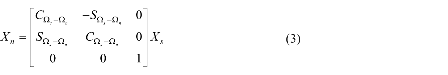
where
As the ball moves along the helical groove of the screw, the angular displacements of the ball are
The relationship between the Frenet coordinate frame

where
Velocity analysis at the contact point
In this article, when the rotational velocities of the micro-feed mechanism are very low, many parameters can be disregarded. On the basis of the analysis results of Wei et al.,
7
the assumptions used in this article are based on four hypotheses: (1) the friction coefficients in the ball–nut and ball–screw contact areas are equal,
The working ball is confined along the helical groove in directions parallel to the normal plane of the trajectory of the ball center; therefore, the ball can only move relative to the screw in the tangential direction of the Frenet frame of the ball center trajectory. 3 Figure 3 shows the position coordinates of the contact points.
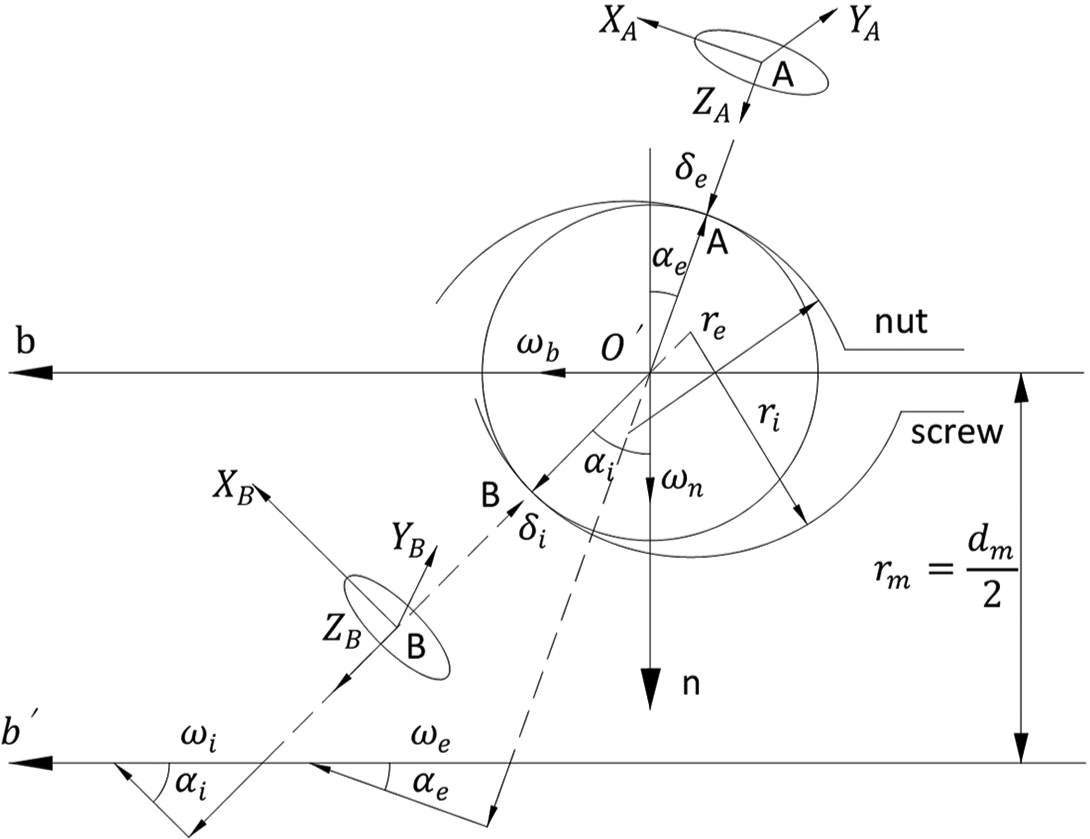
Position coordinates of contact points.
The contact point coordinate system

where
Given that the elliptical contact area is significantly smaller than the ball radius, the contact angles are equal in the contact ellipse, that is,
The ball center’s position vector,

The ball center’s position vector,

where
The ball center’s velocity relative to the screw rotating coordinate can be calculated by differentiating equation (6) with respect to time

where
The ball center’s velocity relative to the world coordinate can be calculated by

Let


The velocity coordinate of the contact point.
The instantaneous velocity of the ball’s point A, which is coincident with the contact point between the nut and the ball, can be expressed as

where
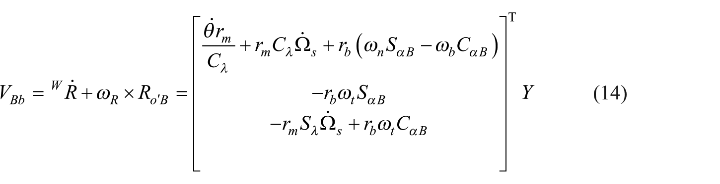
The instantaneous velocity of the point B on the ball, which is coincident with the contact point between the screw and the ball, can be expressed as
The instantaneous velocity of the point A on the nut can be expressed as

where
The instantaneous velocity of the point B on the screw can be expressed as

where
The slip velocity at the point A between the nut and the ball is given by

The slip velocity at the point B between the screw and the ball is given by
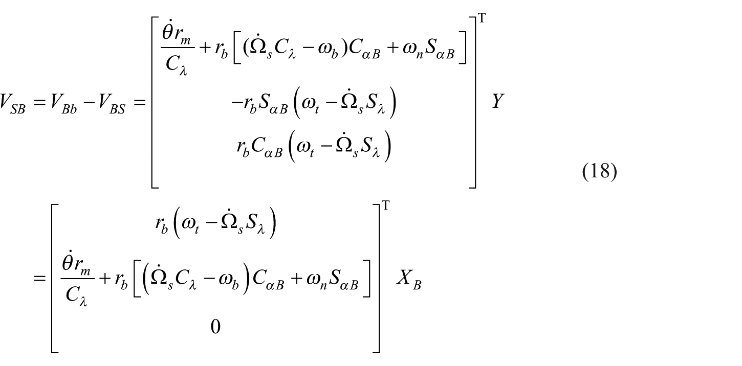
Figure 3 also shows the contact conditions of the ball–nut and ball–screw interfaces. In the figure,

where
Similarly, a point of pure rolling is assumed in the ball screw elliptical contact area, and this point is approximate to point B at the center of the contact ellipse. Equating the linear velocities of the ball and the screw at this pure rolling point is given by

where
Substituting equations (11) and (12) into equation (19) gives the rearranged form as
Similarly, substituting equations (11) and (12) into equation (20) gives the rearranged form as

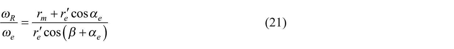
In practical applications, the nut moves in the axial direction as it rotates; therefore, the relationship between the angular velocity of the nut or screw and the angular velocity of the ball can be written as


where
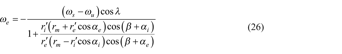
Similarly, substituting equations (21) and (22) into equations (23) and (24) obtains the screw’s relative angular velocity with respect to the ball, as follows

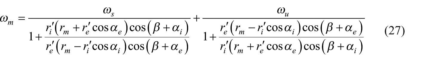
The nut’s relative angular velocity with respect to the ball is given by
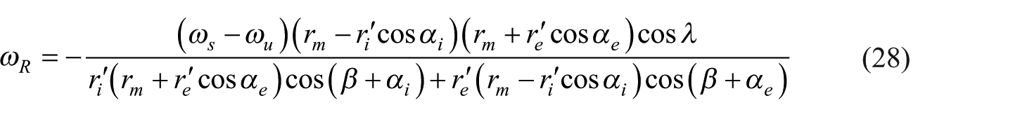
The ball’s revolution around the screw axis is given as
The ball’s spinning velocity is obtained as
The elastic deformation of the contact point is significantly smaller than the ball radius, and the pure rolling point is significantly close to the center of the contact ellipse; therefore,

Analysis of the deformation geometric relationship
Figure 5 shows the deformation geometric relationship. In the figure,

where

Deformation geometric relationship.
Geometric analyses for Figure 5 give


where
Using the Pythagorean theorem in Figure 5, it can be obtained that


According to the above geometric deformation equations, the contact angles of the ball–nut and the ball–screw,
Analysis of the force balance
Figure 6 shows the stress analysis on the nut at the ball–nut contact point parallel to the
Force balance analysis of the nut at the contact point of ball–nut.
The balance equation for the stress in the nut can be written as

where
In the static state, the relation between normal force

Figure 7 shows that all forces are acting on a ball.

Force balance analysis of a ball.
The force balance equation for the ball in the t direction, which is actually parallel to the

The force balance in the n-direction, as Figure 7 shows, is given as

The force balance in the b-direction is given by

where
The hydrodynamic pressure distributions are difficult to obtain by elastohydrodynamic lubrication analysis in the contact areas. Therefore, the Hertz contact stress is used to obtain the approximate solution for the hydrodynamic pressure. Thus, the pressure distribution is

where
They are expressed as

where
The normal force is applied and accompanied by an elastic deformation arising in the contact area. The relationship is defined as
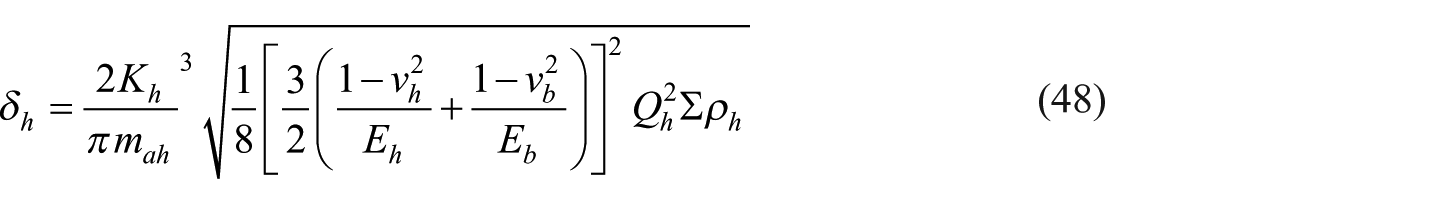
where 2K h / πm ah is the coefficient of the elastic modulus.
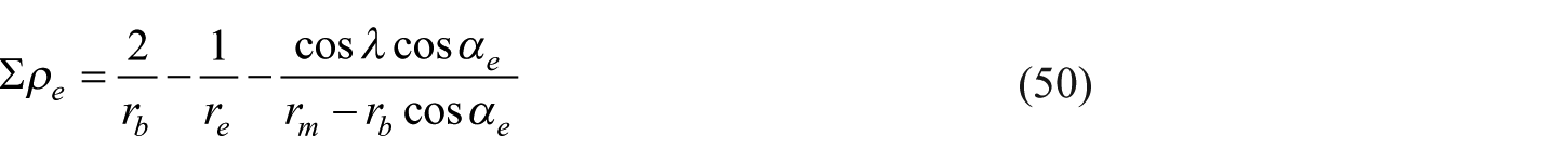
The curvature sum of the screw and ball is defined as

The curvature sum of the nut and ball is defined as
From the principal curvature function,
2
the values of coefficients
Calculation of the frictional force
The frictional force in the ball screw mechanism is used to resist torsional moment, which can reduce mechanical efficiency, produce thermal deformation, and consequently degrade positioning accuracy. The kinematic characteristics of the ball screw pair were studied by Wei and Lin 6 and Wei et al., 7 who calculated the friction between the ball and the roller using the Coulomb friction model. To obtain the exact value of friction, Olaru et al. 20 proposed an improved Coulomb friction model. In general, the demands of engineering practice in the low-precision level can be met using the Coulomb friction model. However, this model has some limitations under high-precision and low-velocity conditions; thus, the Coulomb friction model is not a good predictor of the value of friction. By contrast, the LuGre friction model, 21 which was proposed by Canudas de Wit et al. to solve the friction on a table, can accurately describe the static and kinematic characteristics of friction, including pre-slip displacement, friction hysteresis, variable static friction, crawling, and Stribeck effect.
The LuGre friction model visualizes contact surfaces as two rigid bodies that establish contact through bristles, as shown in Figure 8. The stiffness of the lower surface material is greater than that of the upper surface material. When an external force is exerted, the bristles deform like springs, thereby generating the frictional force. State quantity


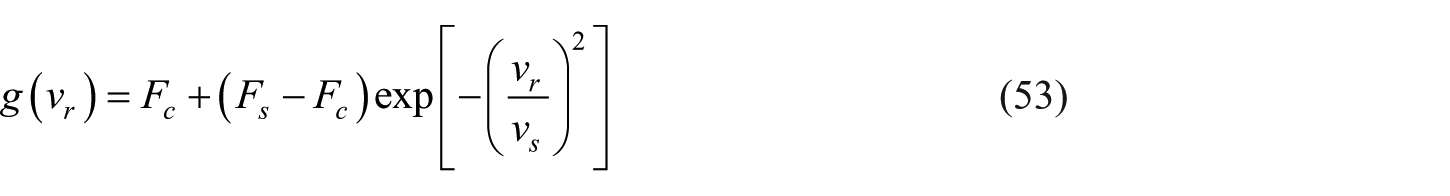
where

LuGre frictional model between guideway and table.
When the system is in steady state, then

The friction simulation model between the guideway and the table is shown in Figure 9, and the model is completed through Simulink.

Simulink subprogram of friction model.
The Coulomb frictions of ball–nut contact area in


where µ
e
represents the friction coefficient produced at contact area of ball–nut.

where
The Coulomb frictions of ball–nut contact area in


where µ
i
denotes the friction coefficient produced at contact area of ball–screw.

where
Calculation of the mechanical transmission efficiency
The mechanical transmission efficiency of the dual-driven ball screw mechanism is equal to the ratio of output power to input power. Taking a single ball as research object, the output power can be written as

where
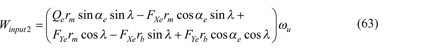
The input power of the dual-driven ball screw mechanism is equal to the sum of the input power of the screw motor and the input power of the nut motor. With a single ball as the research object, the expression of the input power of the screw motor is written as

Similarly, the expression of the input power of the nut motor is written as
The total input power associated with frictions generated at the contact areas of ball–nut and ball–screw is given by

The mechanical transmission efficiency of the dual-driven ball screw mechanism is defined as

Simulation and analysis
In this study, the parameters of the geometric and operating conditions of the dual-driven ball screw mechanism are shown in Table 1. The dual-driven ball screw mechanism realizes micro-feeding; therefore, the velocities of the screw and nut are low, and the difference between these velocities is minimal.
Geometric parameters and operating conditions.

Flowchart of numerical analysis
Figure 10 shows the flowchart illustrating how all the parameters related to the kinematic behavior of the dual-driven ball screw mechanism are obtained sequentially by numerical analyses from the satisfaction of the convergence criterion. Given the parameters of the geometric and operating conditions of the dual-driven ball screw mechanism in Table 1, the study assumes an initial value for the angular displacement

Flowchart of the numerical analysis.
Analysis of the velocity
Figure 11(a) shows the rotational velocity of a single-driven ball screw mechanism when the screw speed is 1 rad/s and the nut does not rotate. Figure 11(b) shows the rotational velocity of the synthesized dual-driven mechanism, whose screw and nut angular velocities are 11 and 10 rad/s, respectively.

(a) Rotary velocity of single-driven mechanism and (b) rotary velocity of dual-driven mechanism.
The foremost characteristic of the dual-driven micro-feed mechanism is its capability to demonstrate a stable velocity under a minimal speed difference, without being influenced by the nonlinear friction. Yu and Feng 22 studied the micro-feed feature of a dual-motor servo system by considering the impact of friction. This study focuses on the low-speed characteristics of the dual-driven ball screw mechanism, and it finds that the speed of the screw demonstrates a noticeable crawling phenomenon when the speed of the screw motor is 1 rad/s under the single-driven condition, according to the repeated simulated system parameters. However, the composite speed of the screw and nut is very stable when this speed is equal to 1 rad/s under the dual-driven condition. As shown in Figure 11, the dual-driven mechanism can output a lower stable velocity and a better low-speed micro-feeding performance than the single-driven mechanism.
Analysis of the frictional force
Figure 12(a) and (b) show that the frictional forces at the nut–ball and screw–ball contact points change with a change in the screw rotational velocity under the single-driven condition. Figure 13(a) and (b) display that the frictional forces change at the nut–ball and screw–ball contact points with a change in the composite rate under the dual-driven condition and when the axial force is 500 N.

(a) Frictional force of single-driven at ball–nut contact point and (b) frictional force of single-driven at ball–screw contact point.

(a) Frictional force of dual-driven at ball–nut contact point and (b) frictional force of dual-driven at ball–screw contact point.
As shown in Figures 12 and 13, the frictional forces at the two contact points change continuously in the form of negative damping when the screw rotational velocity is lower than 4 rad/s under the single-driven condition; this phenomenon is known as the Stribeck effect. By contrast, the frictional forces at the two contact points increase linearly and slowly when the nut rotational velocity is higher than 2 rad/s and the rotational velocity difference is greater than 0 rad/s
Analysis of the angular velocity for the revolution of the ball
Two angular velocities are produced in a ball when the ball screw mechanism operates under single-driven or dual-driven conditions. These two angular velocities are expressed in absolute values. Figure 14(a) and (b) show the change in the angular velocity for the revolution of the ball when single-driven and dual-driven, respectively.

(a) Ball’s revolution angular velocity with single-driven and (b) ball’s revolution angular velocity with dual-driven.
As shown in Figure 14(a) and (b), the angular velocity for the revolution of the ball increases linearly as the angular velocities for the rotations of the screw and nut increase but does not change with a change in axial force. In addition, the angular velocity for the revolution of the ball is higher under the dual-driven condition than that under the single-driven condition. Therefore, the dual-driven mechanism has a higher speed and responds more quickly at the same feed rate.
Analysis of the mechanical transmission efficiency
The changes in the mechanical transmission efficiency of the dual-driven mechanism as the speed differences between the screw and nut change are shown in Figure 15. When the nut rotational velocity is constant, the mechanical transmission efficiency initially increases and subsequently decreases as the rotational velocities of the screw and nut increase. The linear growth rate of the output power is greater than that of the input power at a low speed; as a result, the mechanical transmission efficiency presents an increasing trend at a low speed. When the speed difference continues to increase, the proportion of consumed power resulting from increased friction increases; thus, when the speed difference is greater than a certain value, the mechanical transmission efficiency is reduced as the speed difference increases.

Mechanical transmission efficiency of the dual-driven ball screw mechanism.
As shown in Figure 15, when the nut rotational velocity is equal to zero, the mechanical transmission efficiency of the single-driven mechanism is higher than that of the dual-driven mechanism. The dual-driven micro-feed mechanism obtains high accuracy by sacrificing mechanical transmission efficiency; thus, high micro-feed accuracy and transmission efficiency are contradictory.
Conclusion
In this study, a new dual-driven ball screw micro-feed mechanism is designed. By studying the working ball in the helical raceway and using the principle of differential geometry to analyze the motion of the ball under the dual-driven condition, we find that the stable output velocity under the dual-driven condition is lower than that under the single-driven condition; therefore, the dual-driven mechanism is more suitable for micro-machining.
Comparing the frictional forces at the ball and raceway contact points under the dual-driven condition and under the single-driven condition, we find that the friction changes continuously and demonstrates negative damping, that is, the Stribeck effect, under the single-driven condition. However, the friction at the two contact points increases linearly and slowly as the speed difference increases in the dual-driven mechanism; consequently, the influence of the low-speed nonlinear crawling phenomenon caused by friction in traditional electromechanical servo systems can be avoided.
The revolution velocity of the ball increases linearly as the angular velocities of the screw and nut increase, and the angular velocity under the dual-driven condition is higher than that under the single-driven condition. Therefore, the dual-driven mechanism has a higher speed and responds more quickly at the same feed rate.
When the nut angular velocity is constant, the mechanical transmission efficiency initially increases and subsequently decreases as the angular velocities of the screw and nut increase. The mechanical transmission efficiency of the single-driven mechanism is higher than that of the dual-driven mechanism. However, the dual-driven micro-feed mechanism obtains high accuracy by sacrificing mechanical transmission efficiency, indicating that high micro-feed accuracy and transmission efficiency are contradictory.
Footnotes
Appendix 1
Authors’ note
The authors would like to declare that the work described was original research that has not been published previously and is not under consideration for publication elsewhere, in whole or in part.
Declaration of conflicting interests
The author(s) declared no potential conflicts of interest with respect to the research, authorship, and/or publication of this article.
Funding
The author(s) disclosed receipt of the following financial support for the research, authorship, and/or publication of this article: This study was supported by the Natural Science Foundation of Shandong Province, China (grant no. ZR2019PEE006); National Natural Science Foundation of China (grant no. 51375266); Special Fund Plan for Local Science and Technology Development led by Central Authority in China; and the Shandong Province Higher Institution Science and Technology Plan Project (grant no. J17KA028).