
Abstract
The thread connection’s root fillet radius of 0.038″ size is the greatest weakness of the API NC type joints and thread. During the slimehole drilling, especially in the deep and ultra-deep gas well, its stress concentration factor and notch sensitivity factor are very high A novel thread connection design (TM) of a drilling tool is proposed to decrease the fatigue failure of the slimehole drilling tool in the deep and the ultra-deep gas well in the Tarim oilfield China. The novelty in the TM thread structure is, reducing the threads per inch, extending the distance from the last engaged thread to the external shoulder of the pin and adding three threads to the conventional connection. The novel thread connection will improve the slimehole drilling tool’s anti-fatigue life due to its improved elasticity and rigidity. Furthermore, the TM can transfer the maximum stress at the connection root to the loaded surface, which can effectively lower the fatigue notch’s sensitivity coefficient. In this paper, the finite element method (FEM) is applied to carry out the detailed comparative analysis of the TM with existing thread connection NC38, TX60 and TH90. The TM has the lowest stress concentration factor and fatigue notch sensitivity coefficient, so its anti-fatigue life is the highest. In addition, TM is manufactured and is tested at Tarim oilfield in China.
Keywords
Introduction
The thread connection’s root fillet radius of 0.038″ size is the greatest weakness of the API NC type joints and thread. During the slimehole drilling, especially in the deep and ultra-deep gas well, its stress concentration factor and notch sensitivity factor are very high.1,2 API stress-relief grooves cannot solve the fatigue fracture problem.3–5 Sometimes, fatigue crack is initiated and is propagated in the joint’s last engaged threads, which may lead to piercing or fracture of the joint.6–9 Some manufacturers have recognized the previously mentioned problem.10,11 Based on the existing joint thread design, they changed the API connection root’s fillet radius to a double circular arc with 0.052″+ 0.060″ radius. The Grant has also changed the TT type connection root’s fillet radius to a double circular arc with 0.060″+ 0.065″ radius, which considerably reduces the stress concentration factor and the notch sensitivity factor. The joint alloy material can be improved by adding steel, which increases the fatigue life of the joint thread by 8–9 times, compared with the API NC type connection. Many researchers published work on improving joints of drilling tools anti-fatigue life. They mainly focused on the issue of drilling tools material itself,12–14 and modifying the thread structure or investigating on how the stress concentration factor and the notch sensitivity factor changing with different thread structures,15–17 which provides a theoretical basis for the modification of the joint of drilling tools to improve their anti-fatigue life.
In order to improve the anti-fatigue life on a thread connection of slimehole drilling tools in deep or ultra-deep gas well in Tarim oilfield of China, a novel premium connection structure of slimehole drilling tools with 120.62 mm (43/4″) joint diameter has been designed and developed in this paper. This premium connection satisfies the requirements of the exploratory development of Tarim oilfield of China in deep and ultra-deep gas wells. The premium connection is called TM. The TM thread connection profile is shown in Figure 1, where R1 and R2 represent the double circular arc radius of the thread root bottom. Similarly, Ra and Rb are the double circular arc radius of the thread root top. The loaded surface bears torque and axial force, so the flank angle on this side is designed 30°. While, the guiding surface suffers no stress, and the flank angle on this side is 45°. The innovation features of TM are: three threads per inch, the tapper is 1:16, and the flank angles of the loaded and guiding surfaces are 30° and 45°, respectively. Meanwhile, the TM extends the distance from the last engaged threads to the external shoulder of the pin connection, and adding three more threads than a conventional box. With decreased rigidity and increased elasticity, this thread structure will improve anti-fatigue life.

TM thread connection profile.
Finite element mechanical model
Based on the novel design of the TM type thread, a finite element mechanical model is established in this paper, as is shown in Figure 2(a). The TM has are more threads on the back of the box thread’s base plane that belongs to a non-intermeshing thread structure. This feature will decrease the last engaged thread rigidity and will improve the stress concentration. Figure 2(a) shows that the distance from the last engaged pin threads to the external ledge of the pin thread is L. The length of L is two to four times longer than conventional screwed joints. In the model, contact pressure after screwing on is applied on the external shoulder AB plane and inner shoulder CD plane. Their contact pressure is P1 and P2, respectively. Their value can be calculated by the Farr formula, given by (1), which is recommended by API RP7G standards. 1

Where, P is the contact pressure between the shoulders, kN. Tn is making-up torque, kN·m. h is the thread pitch, mm. Rt is the average radius of thread, mm. f is the friction coefficient among the connection shoulders. Rs is the connection shoulder average radius, mm. θ is the thread half-angle, °.

Finite element mechanical model of TM lengthened thread: (a) solid model and (b) mesh model.
The finite element model is axial symmetry and its boundary conditions are that, at the bottom of the pin is applied axial fixed constraint, and at the top of the box is applied pressure T. Contact surface is defined between the external thread and the internal thread. Under axial loads, the model can be simplified as an axisymmetric model. An axil compressive force, T, is applied on the pin thread. The joint bottom is constrained. The FE mesh near the thread teeth is more refined than in other regions. The meshed model is shown in Figure 2(b). A pair of active force and reactive force P1 is applied on the external shoulder AB plane, which is the contact surface between the top of the pin thread and the external shoulder of the box. And a pair of active force and reactive force P2 is also applied on the internal shoulder CD plane which is the contact surface between the pin and the box as well. As is shown in Figure 2(a). When the bit pressure T = 0, that means the axial force is 0, stress in the connection is all generated from the making-up torque.
Simulation results
TM FE simulation results are shown in Figures 3 and 4. In Figure 3(a), the maximum Von-Mises stress is mainly in the two ends of the threads. The new feature of three more threads can improve the distribution of stress in the threads. The maximum principal stress is transferred from connection root to the loaded surface.

Distribution of stress and flank pressure of TM: (a) Von Mises stress and (b) pressure distribution.
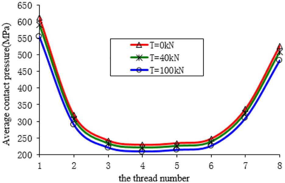
Average contact pressure curves on TM thread loaded surface.
The distribution of contact pressure on the thread-loaded surface in the model is shown in the Figure 3(b). There are eight loaded surfaces in the TM connection, and the value of contact pressure is shown in the Figure 4. Figure 4 shows the distribution of the contact pressure on the different position of screw. In the Figure 4, the 1st and 8th threads are both the end of the connection position and subjected to the biggest average contact pressure. In addition, contact pressure on the middle of connection from the third thread to the sixth thread is much smaller than that of the 1st and 8th threads, and tend to be equal. The contact pressure on the second thread and seventh thread is medium compared by the whole contact pressure on the connection. Therefore, the thread failure and damage occurred on the both ends of the connection. Three contact curves were given in the Figure 4 when axial pressure T is 0, 40, 100 kN, respectively. The contact pressure on the connection decreases with increasing axial compression force T from 0 to 100 kN. That means some part of the contact pressure generated by the making-up torque was balanced out. This is the reason why drilling tools should be applied a certain making-up torque during the process of drilling operation.
Finite element models
FE models of connection root
In order to make a further study for the TM connection in this paper, finite element analysis on the four types TM, TX60, NC38, and TH90 connections was carried out. The stress distribution of their connection root, stress concentration factor Kt, and notch fatigue sensitivity coefficient Kf are systematically investigated.
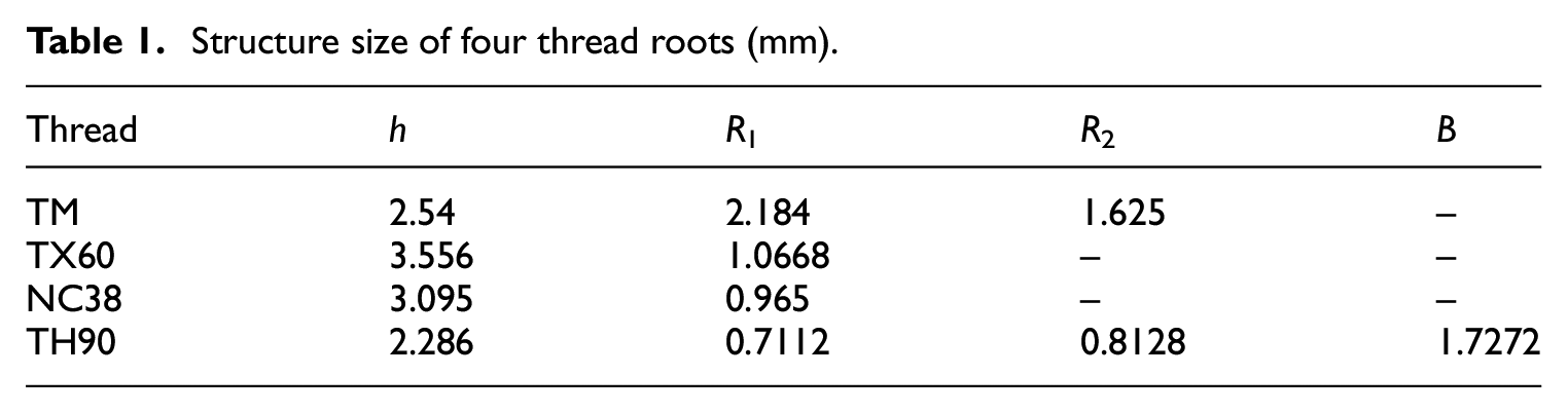
The four finite element models of the connection root are shown in Figure 5(a)–(c). The magnification models of their connection root structures are shown as in Figure 6, and the basic structure parameters of their connection roots are shown in Table 1. In the Figure 5, the boundary conditions for the four finite element models are; EF is fixed, and CD is under tensile stress σ0. The maximum elastic stress

Finite element mechanical models of four connection roots: (a) TM, (b) TX60 and NC38, and (c) TH90.

Magnification of connection root structures: (a) TM, (b) TX60 and NC38, and (c) TH90.
Structure size of four thread roots (mm).
Stress analysis of connection root
The Von-Mises stresses near the connection root are shown in Figure 7(a)–(d), under the tension force σ0 of 400 MPa. The stresses in the four models reached the plastic deformation near the connection root of point A. Red region in the Figure 7 represents the connection root material’s plastic zone. The plastic zone mainly appears up to distance 0.5 mm from the connection root of point A, while elastic stresses dominate the rest of the domain.
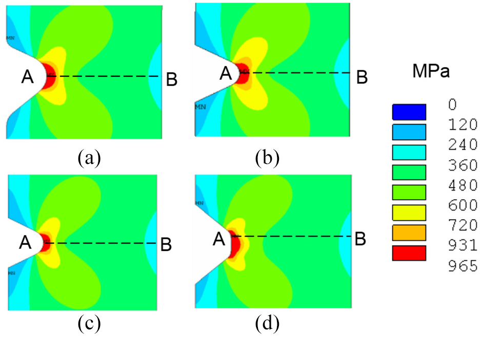
Stress distribution of connection roots (σ0 = 400 MPa, red zone represents plastic zone): (a) TM, (b) TX60, (c) NC38, and (d) TH90.
The stress concentration factor, Kt, is the ratio between the maximum elastic stress and the nominal stress in the elastic range, which is shown as:

Where,
Therefore, the tension force σ0, applied on the mechanic models in Figure 5(a)–(c), is reduced from 400 to 150 MPa. And the curves of four types of connection roots stress distribution along with path AB are shown in Figure 8. The maximum stresses in the curves are all less than the yield stress of S135 drilling tool 931 MPa. As shown in Figure 8, the connection root stress of TM connection is 559 MPa, which is the smallest among the four types of connections. However, the connection root stress of the TX60 thread is 727 MPa, which is higher than the rest. Therefore, the structure of the TM premium connection is more practical than the other three types. TM achieves the purpose of improving the distribution of stress and reducing the stress concentration.

Stress distribution curves along path AB.
The tension force σ0 is incrementally increased from 50 to 500 MPa to investigate the maximum stress at the connection root for the four types of thread structure. The four maximum stresses at the connection roots versus tension force σ0 is shown in Figure 9. Figure 9 shows that the connection root stress of the TX60 thread is the highest, and the next one is the TH90 thread. The lowest stress at the connection root is for connection TM. Therefore, the TM mechanical design is the most practical one.
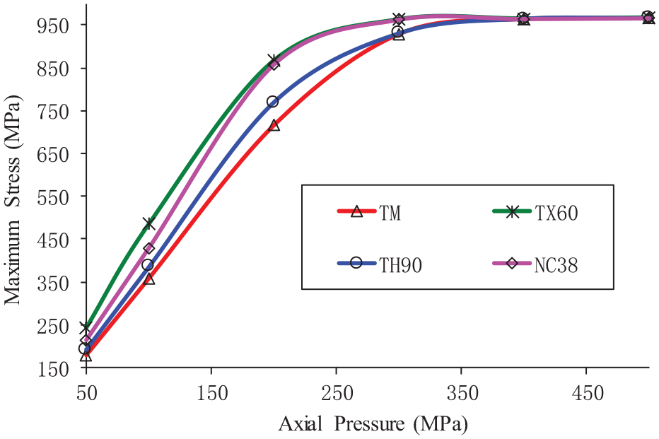
Relationship between σmax and σ0.
Stress concentration factor and fatigue sensitivity coefficient analysis
For a simple thread structure, the stress concentration factor, Kt 16

where, Kt is the stress concentration factor, t is the depth of tooth, ρ is the fillet radius of the connection root. However, for some complicated thread structure, Kt must be calculated using equation (2), where

Where, Se is the fatigue strength of the smooth sample, Sw is the fatigue strength of the notch sample.
Experimental studies 18 show that material plasticity is one of the main factors affecting fatigue notch sensitivity coefficient Kf. Ductile material has Kf that is much lower than Kt. This means the fatigue strength is insensitive to notch. However, for brittle materials, Kf is close to Kt, which means fatigue strength is sensitive to notch. 16 Basing on the model of the stress concentration factor, the fatigue notch sensitivity coefficient Kf is proposed by Peterson. It is assumed that the stress decreases linearly from the notch root toward the interior, as is shown in Figure 10. The fatigue damage is expected when the mean stress at the position of notch root reaches to or larger than the material’s fatigue strength. So the relationship between Kf and Kt is. 16

Where, ρ is the notch root radius, a is a material constant, for quenched and tempered steel a = 0.635 mm, and for normalizing steels a = 0.254 mm.

Sketch map of notch.
The stress concentration coefficient in a simple thread structure can be obtained by equation (3). However, the thread structure of drilling tools joint is very complicated in the petroleum industry and it is not recommended to calculate it using equation (3). So, initially, the maximum stress of threads notch σmax is obtained by the finite element method. Then, the stress concentration coefficient is obtained using equation (2). Finally, its fatigue notch sensitive coefficient is calculated using equation (5).
Using the finite element models in Figure 6(a)–(c), the maximum stress in the elastic region can be estimated. Combining equation (2)–(5), stress concentration coefficient Kt and notch fatigue stress concentration coefficient Kf for the three types of threads, TM, TX60 and NC38, can be obtained, and shown in Table 2. However, the stress concentration coefficient Kt and notch fatigue sensitive coefficient Kf of TH90 type thread cannot be estimated using equation (3) and (5). Since the bottom of the TH90 thread is a trapezoid, and the fillet radius ρ is uncertain. In this situation, the stress concentration coefficient Kt can be obtained only by the method of finite element analysis. Firstly, the finite element method is employed to calculate the maximum local elastic stress. And then, combining with equation (2), the stress concentration Kt will be obtained. Moreover, the stress concentration coefficient, which is calculated using finite element analysis, is more reasonable than the one is calculated using the theoretical formula. Since, the theoretical formula is derived from the theory of a thick-walled cylinder, while, the finite element method is applied to the real design. From the Table 2, the stress concentration coefficient of TM premium connection is 3.59, which is the lowest stress concentration coefficient among the four threads types. In addition, the stress concentration coefficient of TX60 is 4.85, which is the highest one. The TX60 mechanical designs are the worst. Based on the above results, the TM is the best structure design in comparison to the others. In addition, this structure can improve the anti-fatigue life of the thread joint effectively in the deep and ultra-deep gas well drilling. Meanwhile, the fatigue’s notch sensitivity coefficient of TX60 is the highest one.
Computed results of stress concentration coefficient and fatigue notch sensitive coefficient.

Manufacture and application of TM
The TM thread profile sketch is shown in Figure 1, and the manufactured part is shown in Figure 11. The slimehole drilling tool with the TM thread has been applied in more than 20 deep and ultra-deep gas wells in the Tarim oilfield, China, which is recorded by the drilling tools company. And the TM thread has validated that its anti-fatigue life is much longer than the other thread joint existing used in the Tarim oilfield. Compared to conventional API joint and drilling tools joint manufacture, the TM thread profile changed the parameters of thread structure design, which can decrease the stress concentration and notch sensitive coefficients, which improves its anti-fatigue life. Now, slimehole-drilling tools with the TM thread joint are successful in Tarim Oilfield, in China. In addition, it is suitable for the other deep and ultra-deep gas wells in the world.

Manufacture of TM.
Conclusion
The basic weakness of the API NC thread joint is that the fillet radius of its connection root is 0.038″. In an inevitable working condition of rotating and bending, its stress concentration and notch sensitivity coefficients are high. Moreover, API stress-relief grooves cannot solve the fatigue fracture problem.
The TM thread structure is designed with reduced tooth per inch; extending the distance from the last engaged pin threads to the external shoulder of the box and three more threads than a conventional box connection. With decreased rigidity and increased elasticity, this thread structure will improve anti-fatigue life.
The TM thread structure can transfer the maximum stress of the connection root to the thread guiding surface, which can effectively lower the fatigue’s notch sensitivity coefficient.
Through comparative analysis of TM, NC38, TX60 and TH90 thread structure, the stress concentration and fatigue notch sensitivity coefficients of the TM thread are the lowest, and it has the longest anti-fatigue life. Therefore, the slimehole drilling tools with TM thread joint can meet the requirements of severe conditions in the deep or ultra-deep gas well drilling in the world.
Footnotes
Declaration of conflicting interests
The author(s) declared no potential conflicts of interest with respect to the research, authorship, and/or publication of this article.
Funding
The author(s) disclosed receipt of the following financial support for the research, authorship, and/or publication of this article: This research was financially supported by the National Natural Science Foundation of China (No. 51974271), Key Research and Development Plan of Sichuan Province (No. 2020YFSY0038), Open Fund of State Key Laboratory of Oil and Gas Reservoir Geology and Exploitation Southwest Petroleum University (No. PLN201911).