
Abstract
The sealing performance will directly affect the operation of downhole robot under HTHP condition. Traditional analysis methods of sealing performance are that the temperature and pressure is loaded respectively. This can not really evaluate the sealing performance. Besides, the simulation process is: Step 1: pre-compress O-ring to produce contact force. According to the contact pressure, select the compression ratio to calculate the displacement of the slip ring. Step 2: load fluid pressure on the O-ring. This simulation method is to directly load pressure on the undeformed O-ring. However, the O-ring will deform after pre-compression. Therefore, this simulation method is not accurate. In order to make the simulation data more accurate, calculate the data of shape, stress, and strain of O-ring caused by pre-compression caused by assembly. Then, import the deformation body containing the real data of shape, stress, and strain into a new model. On the basis, establish the numerical simulation model of piston, piston guide rod, O-ring, and FTS-ring with HTHP loads is. Finally, calculate and analyze. When the compression ratio of the O-ring is about 14%, the sealing performance is good. What’s more, the distribution of contact stress and Von Mises of the O-ring at 8.3 mm/s of motion speed are analyzed. The results show that the foot shaped combined sealing structure can keep a good dynamic sealing performance under HTHP condition. This paper provides a theoretical basis for the analysis of the dynamic sealing performance by using HTHP coupling method. In the analysis of sealing performance: the hydraulic pressure is loaded to the real model with the real shape, stress, and strain produced by the O-ring assembly. This can more accurately evaluate the sealing performance under HTHP condition. It also provides a reference for the dynamic sealing structure design of downhole tools.
Keywords
Introduction
Coiled tubing drilling technology has many advantages, such as lower cost, less pollution, 1 easier to be automation and intelligence, etc. than the conventional drilling. 2 Due to the axial friction force, the coiled tubing is prone to buckle and “lock up” in horizontal wells. 3 In view of this situation, many scholars have studied the technical bottleneck of “locking up” caused by the coiled tubing buckling. Among them, friction force reducing tools and friction force reducing chemicals are the focuses of the investigation.4,5 Both of the friction force reduction technologies can increase the extension length of the coiled tubing in horizontal wells. However, the extension length of the coiled tubing is still limited.
In order to solve the problem of the coiled tubing buckling, Jørgen 6 proposed a concept of using downhole robots to carry out downhole operations in 1987 for the first time. So far, all the downhole robots can carry out simple operations, such as transportation of logging tool, milling operation of bridge plug, etc. There is not a report about the drilling operation using the downhole robot. It is found that, among the downhole robots, only telescopic downhole robots can meet the drilling requirements. 7 However, the telescopic type of downhole robot is still in the development stage. The high temperature and high pressure resistance of the sealing structure is one of the main reasons restricting the application of telescopic type of downhole robot.
In the aspect of the influence of temperature and pressure on the sealing performance research, Li et al. 8 analyzed the deformation and force condition of the O-ring under different oil pressure conditions range from 0 to10 MPa. Yamabe et al. 9 presented the effects of hydrogen pressure, ambient temperature, and pressure cycle pattern on fracture behavior of O-rings. Zhou et al. 10 analyzed the effects of wedge-ring, hydrogen pressure, and swelling on the sealing performance. Kömmling et al. 11 studied the sealing performance of the casks designed for the storage or transportation. The test temperature was 60°C–150°C. Troufflard et al. 12 simulated the thermo-mechanical behavior of O-ring during the temperature cycle ranging from 20°C to 34°C. As the above researches show, most researchers studied the effect of temperature and pressure, respectively. However, the downhole working condition can always reach to high temperature of 150°C and high differential pressure of 20 MPa. Therefore, it is necessary to analyze the sealing performance of O-ring with HTHP coupling method. In the aspect of dynamic sealing performance research, Huang et al. 13 studied the dynamic sealing performance of the O-ring in the pressure self-adaptive equalizer. Zhang and Xie 14 studied the effects of pre-compression amount, fluid pressure, and friction coefficient on the static and dynamic sealing performances of the O-ring when the pressure is 5 MPa. Tadayoshi and Koji 15 proposed a model of viscoelastic behaviors of the material with Maxwell- hyperelasticity.
In conclusion, current researches on the sealing performance of the O-ring main focus on the effect of working temperature or working pressure respectively, and the studies on the dynamic sealing performance of the O-ring did not be considered. So, there are few researches on the effect of HTHP coupling on the sealing performance of the O-ring. Usually, the downhole temperature can reach to 150°C and the downhole differential pressure of the downhole robot can reach to 20 MPa. Aimed at the sealing structure under the downhole operation condition of the oil and gas drilling, the analysis of the sealing performance with HTHP coupling method is carried out. Furthermore, the dynamic sealing performance with the HTHP coupling method is studied.
Model of combination O-ring under HTHP condition
Constitutive model of rubber material
It can be seen from Figure 1 that the telescopic type of downhole robot consists of left motion unit and right motion unit. Among them, one motion unit consists of telescopic hydraulic cylinder, gripping block, and gripping hydraulic cylinder. The sealing structure is on the hydraulic cylinder. Considering the requirements of dust prevention and sealing, the foot shaped combined sealing structure (FSCSS) is selected as the sliding sealing structure of the telescopic type of downhole robot. FSCSSs are assembled on the gripping hydraulic cylinder and telescopic hydraulic cylinder (Figure 2).

Structure of telescopic type of downhole robot.

FSCSS on telescopic type of downhole robot.
The O-ring in FSCSS is made of oil resistant fluororubber with a diameter of 3.5 mm, which is a high elastic polymer material. The material’s biggest characteristics are incompressibility, high elasticity and high nonlinearity, namely geometric nonlinearity, material nonlinearity, and contact nonlinearity.
The constitutive models of rubber models can be mainly divided into two types: phenomenological model of strain energy and statistical model of molecular chain network. Because the polynomial model of phenomenological theory has high precision, the Mooney Rivlin constitutive model of phenomenological theory is used to describe the mechanical properties of Hyper-elastic Materials under the large deformation conditions. 16 The second parameter function expression is as followed:

where W is strain energy density. C10, C01 are Mooney Rivlin model coefficients of material. I1, I2 are the first and second strain tensor invariants.
Mooney-Rivlin model material coefficient of fluororubber at different temperatures can be obtained, as shown in Table 1 and the friction coefficient is 0.2. 17
Material coefficient of fluororubber at different temperatures.

Material properties
As the structure of FSCSS is consistent in its circumferential direction. The 2D axisymmetric model is selected and the two-dimensional finite element model of piston guide rod, piston, O-ring, and foot type slip ring (FTS-ring) is established. The structure and size of the model refer to FSCSS in the sealing manual. 18 The diameter of the O-ring is 3.5 mm, and the size of the FTS-ring matches the size of the O- ring. PTFE is selected for the FTS-ring. By consulting the literature and material experimental standards, the elastic modulus is 1000 MPa and Poisson’s ratio is 0.29. According to the analysis of heat transfer, the thermodynamic related coefficient of the combined sealing material is obtained, as is shown in Table 2. 19
Thermodynamic related coefficients of the combined sealing material.

Comparing with the O-ring of FSCSS, the elastic modulus of piston and piston guide rod in the model is far greater than that of the O-ring. Therefore, the analytical rigid body is used and the grid division is shown in Table 3. In Table 3, the Unit type of CAX4R is a meshing method for circles. And, the Unit type of CAX3 is for meshing the irregular shape.
Grid division of FSCSS.

Pre-compression simulation model of FSCSS
The conventional simulation method has two steps: Step 1: pre-compress FSCSS to make the O-ring produce contact force. Then, apply radical displacement to the piston guide rod as the compression ratio of the O-ring range from 10% to 25%. Step 2: load pressure on the surface of O-ring and FSCSS, so as to simulate the pressure of the fluid on the O-ring (Figure 3).

Simulation model after pre-compression.
Actually, when the O-ring is assembled, only a part of the O-ring is in contact with the fluid, and the other part of the O-ring is in contact with the piston guide rod and FTS-ring. Because the pressure load of the fluid can only be loaded at the position where the fluid contacts the O-ring. However, in the conventional numerical simulation method, the selection of the contact position between fluid and O-ring is strictly dependent on experience or estimation. Usually, the O-ring is divided into two semicircles, one of which is in contact with the fluid, and the pressure load of the fluid is only one semicircle. In other words, the pressure load of the fluid may not cover the contact area between the fluid and the O-ring completely, or the pressure load of the fluid may exceed the maximum contact area of the fluid. Therefore, the conventional analysis methods do not accurately simulate the real contact state between O-ring and fluid.
In order to make the simulation data more accurate, in this paper, the data of shape, stress, and strain of O-ring caused by pre-compression caused by assembly is calculated before the analysis of the dynamic sealing. Then, import the deformation body containing the real data of shape. This simulation method can accurately calculate the contact position between fluid and O-ring. The pressure load of the fluid can also be accurately loaded on the O-ring (Figure 4). Based on the simulation model, the calculated results are closer to the real state of O-ring. Therefore, the simulation method proposed in this paper is more accurate.

Loading pressure on the model after deformation.
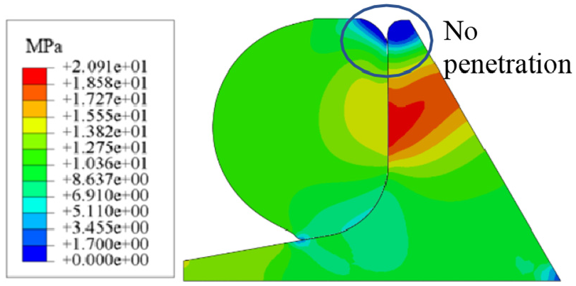
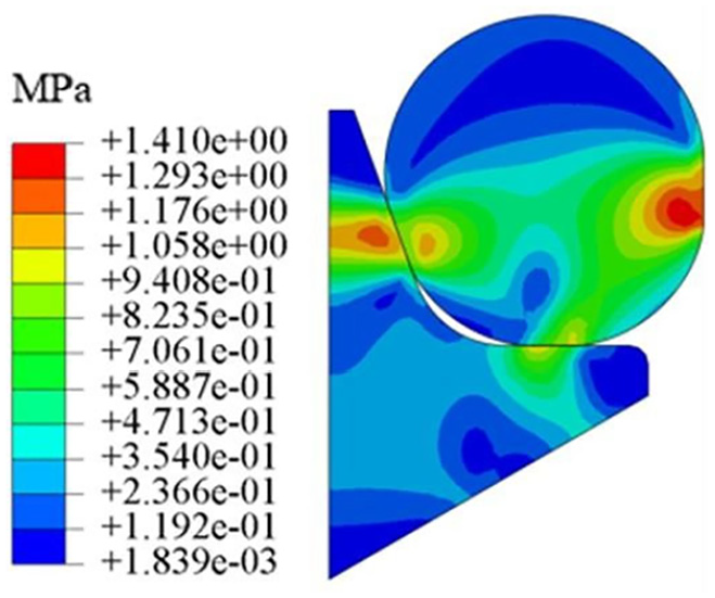
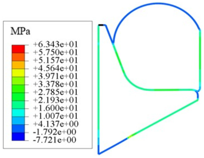
Under the condition of compression ratio of 10% and medium pressure of 10 MPa, the Mises stress distribution of O-ring and FTS-ring was obtained, as shown in Figures 5 and 6. It can be seen from the figure that the shape of O-ring in the conventional simulation model is very irregular and does not effectively contact with FTS-ring. The O-ring has penetrated into the gap between FTS-ring and the piston guide rod. It shows that the O-ring has been seriously damaged, which is not consistent with the actual use of O-ring. In the pre-compression simulation model, the O-ring is in good contact with FTS- ring, and the O-ring is not damaged. Therefore, the pre-compression simulation model can more truly reflect the working state of O-ring. Then the calculation results will be more accurate.

Stress distribution under the condition of conventional simulation model.
Stress distribution under the condition of pre- compression simulation model.
Effect of pre-compression ratio of O-ring on sealing performance
The initial compression ratio is related to the section size and compression height, which can be expressed as follows:

where Δd0 is compression height of sealing ring. d0 is section diameter of sealing ring in natural state. According to the working condition of radial sealing, the pre-compression ratio is generally 10%–25%.
When the pre-compression ratio is large, the contact stress of the O-ring is larger and the sealing performance of FSCSS is better. But the wear will be more serious. When the pre-compression ratio is small, the contact stress is small and the sealing performance of FSCSS is relatively poor. But the wear is less. In this paper, the effect of pre-compression ratio at 10%, 14%, 18%, 22% on the sealing performance is studied.
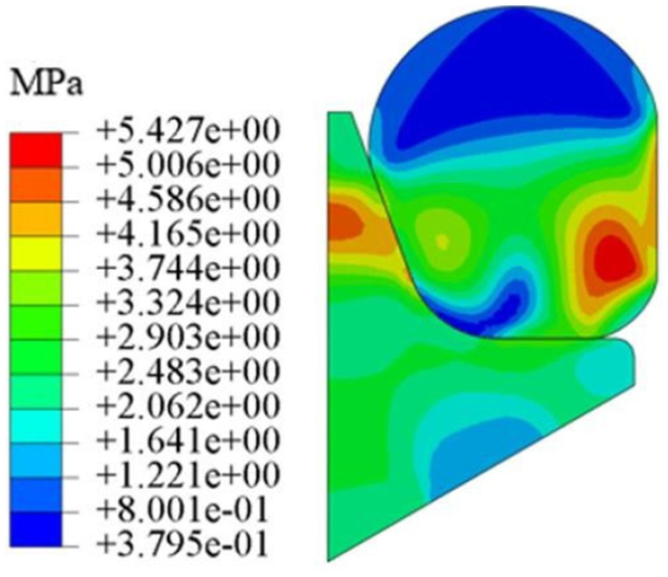
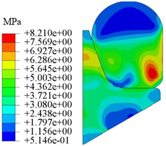
Figures 7 to 14 show the maximum Von Mises of FTS-ring and O-ring with different pre- compression ratios at 20°C and 150°C. It can be seen from Figures 5 to 12 that:
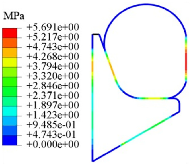
The contact stress of O-ring at 150°C is smaller than that at 20°C. Under different temperatures and pre-compression ratios, the stress of O-ring is mostly concentrated on the left and right sides, and two stress concentrations are formed. The two stress concentrations forms the sealing surface after pre- compression of O-ring.
The maximum Von Mises of O-ring at 150°C is smaller than that at 20°C, and the difference is about 1 MPa. That is to say that the temperature has a great influence on the maximum Von Mises of O- ring. It shows that the damage effect of stress on O-ring is reduced at 150°C, which is conducive to the extension of O-ring life in FSCSS.
Von Mises (compression ratio of 10%, 150°C).

Von Mises (compression ratio of 10%, 20°C).

Von Mises (compression ratio of 14%, 150°C).

Von Mises (compression ratio of 14%, 20°C).

Von Mises (compression ratio of 18%, 150°C).
Von Mises (compression ratio of 18%, 20°C).

Von Mises (compression ratio of 22%, 150°C).
Von Mises (compression ratio of 10%, 20°C).
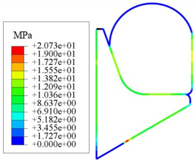
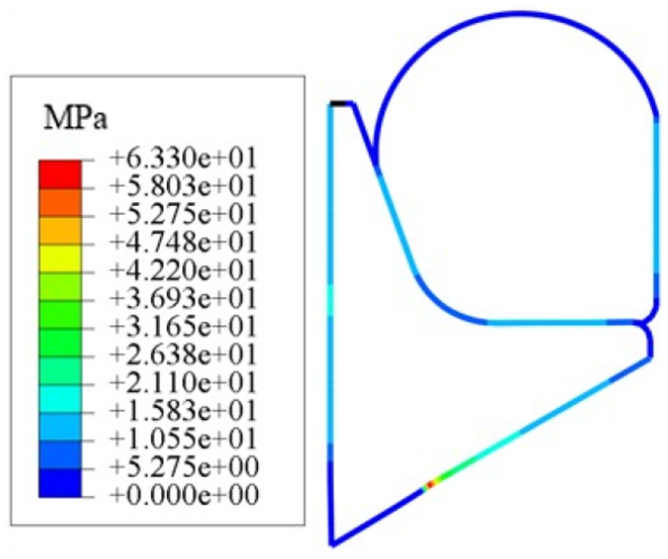
Figures 15 to 22 show the contact stress of FTS-ring and O-ring with different pre-compression ratio at 20°C and 150°C. It can be seen from Figures 15 to 20 that:
When the O-ring is pre-compressed, there is a closed contact surface in FSCSS. It can ensure the sealing performance in the early stage of FSCSS under the pressure of the working medium. With the increase of the pre-compression ratio, the contact surface become larger, and the contact stress increases. The sealing performance will be better.
The contact stress at 150°C is larger than that at 20°C. So, the sealing performance at high temperature of FSCSS is better than that at room temperature.

Contact stress (of 10%, 150°C).

Contact stress (10%, 20°C).

Contact stress (14%, 150°C).

Contact stress (18%, 20°C).
Contact stress (18%, 150°C).

Contact stress (18%, 20°C).

Contact stress (22%, 150°C).

Contact stress (10%, 20°C).
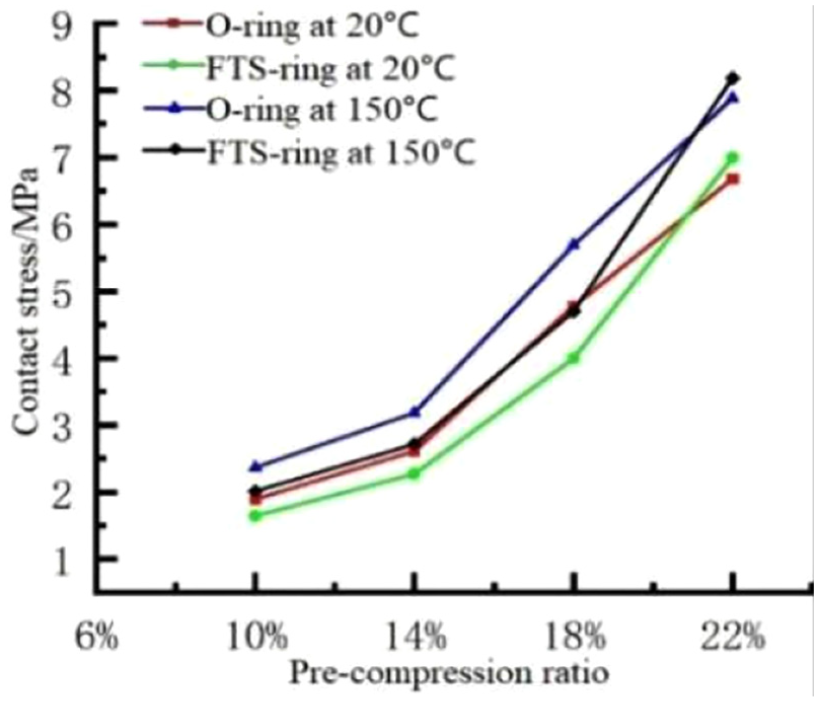
Figures 23 and 24 show the maximum Von Mises and maximum contact stress variation curves under different compression ratios of the O-ring. It can be seen from Figures 23 and 24 that:

Variation of Maximum Von Mises with pre- compression ratio of O-ring.
Variation of Contact stress with pre compression ratio of O-ring.

Contact surfaces of FSCSS.
It can be seen from Figure 26 that contact surface I, contact surface II, contact surface III, and contact surface IV interact to form contact stress. Next, the four contact surfaces are analyzed respectively.
The maximum Von Mises and the maximum contact stress of FSCSS increase with the increase of the pre-compression ratio, which shows a positive correlation.
When the pre-compression ratio is larger than 14%, the maximum Von Mises of FSCSS increases, and the damage effect of the combined seal on the O-ring seal increases rapidly. However, the contact stress increases slowly.

Distribution of contact stress of contact surface I.
On the basis, the O-ring with pre-compression ratio of 14% is selected as the research object to analyze the sealing performance of FSCSS with HTHP coupling method.
Discussion
Static sealing performance
Because there is a hydraulic balance mechanism, the differential pressure between inside and outside the telescopic type of downhole robot is not larger than 20 MPa. Besides, the temperature is about 150°C. So, when the temperature is 150°C, the influence of different pressure (0, 15, 20, 25, 30 MPa) on the sealing performance is analyzed.
Figures 26 to 29 show the distribution of contact stress in each contact surface under different pressure. Figure 26 shows the distribution of the contact stress of contact surface I. It can be seen from the figure that:
The length of the contact surface I is about 5 mm. With the increase of pressure, the contact stress increases.
It can be seen from the figure that all the curves have a trough. The reason for the trough may be that the contact stress is small, resulting in the decrease of the contact stress.
The distribution of the contact stress between 1 and 4 mm is stable, which indicates that the position between 1 and 4 mm is the sealing area. What’s more, the maximum contact stress is larger than the pressure. It is proved that the sealing performance between FTS-ring and piston is good.

Distribution of contact stress of contact surface II.

Distribution of contact stress of contact surface III.

Distribution of contact stress of contact surface IV.
Figure 27 shows the distribution of the contact stress of contact surface II. It can be seen from the figure that:
The length of the contact surface II is about 6.5 mm. The lower position of the O-ring fluctuates more than the upper position. This is because the FTS-ring has a fillet at the lower part of the O-ring, which makes the deformation of the lower O-ring larger than that of the upper part, and further leads to the fluctuation of the contact stress distribution. Therefore, when the O-ring is pre-compressed, the fillet position of the FTS-ring should be closely fitted with the piston guide rod to avoid excessive deformation of the O-ring.
The distribution of contact stress between O-ring and piston guide rod is stable and fluctuates little. The maximum contact stress is larger than the pressure. It shows that the sealing performance between O-ring and piston guide rod is good and there is not a leakage problem.
Figure 28 shows the distribution of the contact stress of contact surface III. It can be seen from the figure that:
The length of the contact surface III is smaller than 3 mm. The distribution of contact stress between FTS-ring and piston guide rod decreases gradually from right to left. This is because the interaction between O-ring and FTS ring decreases with the change of contact position.
The contact stress of contact surface III is larger than the pressure, which indicates that the sealing performance between FTS-ring and piston guide rod is good.
Figure 29 shows the distribution of the contact stress of contact surface IV. It can be seen from the figure that:
The length of the contact surface III is smaller than 5.5 mm. The distribution of the contact stress increases gradually with the increase of the pressure. It can be seen that the deformation of O-ring is gradually increasing, and the contact area at the upper left position has gradually decreased with the deformation of O-ring.
There are two peaks in the contact stress, which correspond to the two sides of the contact between FTS-ring and O-ring, respectively. A trough corresponds to the fillet of the FTS-ring in contact with the O-ring. It can also be seen from Figures 15 to 22 that the fillet position is the last contact part of O- ring and foot type slip ring, so the contact stress is the minimum. The contact stress of the trough is greater than the pressure, which indicates that the sealing effect between O-ring and FTS-ring is good.
From the above analysis, it can be seen that under the conditions of pre-compression ratio of 14%, high temperature of 150°C and high pressure of 10–30 MPa, FSCSS can keep good static sealing performance, thus ensuring the operation reliability of the telescopic type of downhole robot.
Dynamic sealing performance
Assuming that the penetration rate of the telescopic type of downhole robot is 30 m/h, the movement speed of the piston of the downhole robot is about 8.3 mm/s. The up stroke is the extension state of the telescopic hydraulic cylinder, and the down stroke is the retraction state of the telescopic hydraulic cylinder, as shown in Figure 1.
Figures 30 to 39 show the contact stress of FSCSS under different pressure when the piston of the hydraulic system reciprocates.
FSCSS forms a closed contact surface because of the pre-compression O-ring, which ensures the sealing performance of FSCSS when the pressure is low. With the increase of the pre-compression ratio, the contact stress also increases, which can ensure the sealing performance.
At high temperature, the contact stress is greater than that at the normal temperature, which is caused by the expansion and contraction of the sealing materials. It also shows that the sealing performance of FSCSS at high temperature is better than that at normal temperature.
Change of contact stress in up stroke at 10 MPa.
Change of contact stress in down stroke at 10 MPa.

Change of contact stress in up stroke at 15 MPa.

Change of contact stress in down stroke at 15 MPa.
Change of contact stress in up stroke at 20 MPa.

Change of contact stress in down stroke at 20 MPa.

Change of contact stress in up stroke at 25 MPa.

Change of contact stress in down stroke at 25 MPa.

Change of contact stress in up stroke at 30 MPa.

Change of contact stress in down stroke at 30 MPa.
Figures 40 to 43 show the maximum contact stress of the O-ring when the piston moves reciprocally.
It can be seen from Figures 40 and 41 that the maximum contact stress of the contact surface I, contact surface III varies greatly when the piston reciprocally moves. The maximum contact stress between FTS-ring and piston in up strokes is larger than that in down strokes. The maximum contact stress between FTS-ring and piston guide rod in up strokes is smaller than in down strokes. The reason is that when the piston is in up strokes, the FTS-ring is subjected to upward friction. The maximum contact stress between FTS-ring and piston increases. However, the maximum contact stress between FTS-ring and piston guide rod decreases. When the piston is in down strokes, the maximum contact stress between FTS-ring and piston decreases. Also, the maximum contact stress between FTS-ring and the piston guide rod increases. It can be seen from the figure that the maximum contact stress is larger than the pressure when the piston reciprocates, which indicates that there is not a leakage phenomenon. The sealing performance is good.
It can be seen from Figures 42 and 43 that the maximum contact stress of contact surface II and contact surface IV change little when the piston reciprocates. It indicates that the maximum contact stress of the O-ring is little affected by the reciprocating motion of the piston. What’s more, the maximum contact stress on O-ring is larger than the pressure. Therefore, there is not leakage phenomenon on the contact surface. The sealing performance is good.

Maximum contact stress of contact surface I.

Maximum contact stress of contact surface II.

Maximum contact stress of contact surface III.

Maximum contact stress of contact surface IV.
In order to explore the influence of the velocity of the combined sealing structure of telescopic type of downhole on sealing performance, the variation of maximum contact stress of O-ring with velocity under 20 MPa, 150°C and pre-compression ratio of 14% was analyzed. It can be seen from Figure 44 that the maximum contact stress drops sharply from 0 to 2.5 mm/s, and the static seal pressure is far greater than the dynamic seal under the same working conditions. The seal pressure of dynamic seal decreases with the increase of velocity, but the change range is small.

Influence of velocity on contact stress.
From the above analysis, it can be seen that FSCSS can keep good dynamic sealing performance when the piston moves at the reciprocating speed of 8.3 mm/s under the condition of pre-compression ratio of 14%, high temperature of 150°C, and high pressure of 10–30 MPa.
Conclusion
Considering the requirements of dust prevention and sealing of the telescopic type of downhole robot, FSCSS is selected. In order to make the simulation data more accurate, HTHP coupling numerical simulation model of piston, piston sleeve, O-ring, and FTS-ring is established, which introduces the real data of shape, stress, and strain of O-ring caused by pre-compression caused by assembly. It is found that the sealing performance is very excellent when the compression ratio of the O-ring is about 14%. What’s more, according to the limit motion law of the downhole robot, the distribution of contact stress, and Von Mises of the O-ring at 8.3 mm/s of motion speed are analyzed. The results show that FSCSS can keep a good dynamic sealing performance under HTHP condition. At the same time, it is found that under the same pressure, the sealing performance of the telescopic type of the downhole robot under high temperature is better than that under low temperature. This is due to the expansion and contraction of the material. This paper provides a theoretical basis for the analysis of the dynamic sealing performance by using HTHP coupling method. What’s more, it also provides a reference for the dynamic sealing structure design of downhole tools under HTHP condition.
Footnotes
Author contributions
J.G. Zhao put forward the idea of numerical simulation research on the sealing performance of drilling tools under the condition of HTHP coupling. H.X. Peng, S. Han, S.J. Fang, and K.P. Wang calculate the numerical model based on the drilling condition. S. Han and Y. Zhang analyze the sealing performance. Z.X. Zhu and C. Tu are responsible for literature research and text collation.
Declaration of conflicting interests
The author(s) declared no potential conflicts of interest with respect to the research, authorship, and/or publication of this article.
Funding
The author(s) disclosed receipt of the following financial support for the research, authorship, and/or publication of this article: This work was supported by the National Natural Science Foundation of China (No. 52004232, U19A200380), Sichuan Science and Technology Program (No. 2021YJ0403, 2019105), Sichuan Provincial Key Lab of Process Equipment and Control (GK202006) and Research Project of Sinopec Research Institute of Petroleum Engineering (No. 35800000-20-FW1907-0012).