
Abstract
This paper focuses on the effects of the off-design operation of CAES on the dynamic characteristics of the triple-gear-rotor system. A finite element model of the system is set up with unbalanced excitations, torque load excitations, and backlash which lead to variations of tooth contact status. An experiment is carried out to verify the accuracy of the mathematical model. The results show that when the system is subjected to large-scale torque load lifting at a high rotating speed, it has two stages of relatively strong periodicity when the torque load is light, and of chaotic when the torque load is heavy, with the transition between the two states being relatively quick and violent. The analysis of the three-dimensional acceleration spectrum and the meshing force shows that the variation in the meshing state and the fluctuation of the meshing force is the basic reasons for the variation in the system response with the torque load. In addition, the three rotors in the triple-gear-rotor system studied show a strong similarity in the meshing states and meshing force fluctuations, which result in the similarity in the dynamic responses of the three rotors.
Keywords
Introduction
Compressed Air Energy Storage (CAES) has a wide range of potential applications for the generation, transmission, and utilization of electricity. 1 The CAES works is that air is first compressed by a compressor, when there is excess electrical power, which can be stored as the internal energy of high-pressure air. The high-pressure air is subsequently released through an expander to generate electrical power when needed. Due to the energy storage and release processes, the CAES exhibit frequently the characteristics of off-design operation. In order to adapt to the fixed frequency of power grid, during the process of energy release the multi-stage expander of CAES raises the rotating speed to the rated speed at no load, which is relatively high, and then performs a wide range of variable power operations at the rated speed. Therefore, as the key equipment of the multi-stage expander in CAES, the triple-gear-rotor system often operates under variable torque load at a high speed. This imposes higher requirements for the safety and reliability of the triple-gear-rotor system, and the dynamic characteristics of the system need to be studied in detail.
A substantial amount of research has been carried out to reveal the dynamic behavior of the gear-rotor systems, with many studies involving mathematical modeling. Kahraman et al.2,3 studied the nonlinear dynamic characteristics of a spur gear system with the harmonic balance method (HBM) using a single degree of freedom model with backlash and time-varying mesh stiffness. Li et al., 4 established a gear pair model with internal and external periodic excitations. Tamminana et al., 5 developed a finite-element-based deformable-body model and a simplified discrete model to predict dynamic behavior of spur gear pairs. Baguet et al., 6 established a gear-rotor model using the finite element method considering the time-varying meshing stiffness and oil film force. Omar et al., 7 presented a dynamic model taking into account gear size, errors, and faults. Wang et al., 8 proposed a method to determine the gear mesh stiffness, loaded transmission error, and tooth contact stress with tooth profile error. Liu et al., 9 proposed a 2-degree-of-freedom nonlinear dynamic model of helical gears considering lubrication.
The dynamic analysis of the gear-rotor systems has become a significant research focus in rotary machines. Nakagawa et al., 10 established a new torsional coupled vibration model based on bond graph method to research the motion and modal behavior of planetary gear train. Motahar et al., 11 studied the nonlinear vibration of bevel gear with tooth profile modification. Hou and Cao, 12 analyzed the nonlinear characteristics of a GTF planetary gear-rotor system. Samani et al., 13 studied the nonlinear vibration of spiral bevel gears with an innovative method of tooth surface modification. Yoon and Kim, 14 proposed a new smoothening function which is applicable to simulating gear impact phenomena with limiting conditions. Yang et al.15–17 studied the nonlinear dynamic response of a spur gear pair. Kim et al., 18 studied the bifurcation of a heavily loaded rotor with five-pad tilting pad bearings.
As for the research on the torque load in the gear-rotor systems, which is the key parameter of the triple-gear-rotor system in CAES, Guo et al., 19 established a three-dimensional multibody dynamic model of wind turbine gearboxes, investigated the combined effects of gravity, bending moment, bearing clearance, and input torque load on the resulting planet load sharing. Zhou et al.20,21 studied the effects of input torque load on the vibration characteristics of gear-rotor system, and showed that an increase in the input torque load can restrain the chaotic motion when input torque is small, but and the inhibition effect disappears when the input torque becomes large. Mihailidis and Nerantzis, 22 described a novel system capable of applying the test torque and speed according to a given load pattern during gear testing.
Although the above studies have discussed the effects of the torque load on the response of the gear-rotor systems, the variation range of rotating speed and torque load were significantly less than those of the triple-gear-rotor systems in CAES. For the highly promising CAES with power levels of 10,000 kW, the vibration characteristics of their triple-gear-rotor system operation under a large range of variable torque loads at a high rotating speed have not yet been adequately explored, and the dynamic response of the system is poorly understood. The purpose of this paper is to propose a dynamic model suitable for the triple-gear-rotor system in CAES which involves three gear rotors with unbalance excitation, torque load excitation and backlash that lead to variations of tooth contact status. An experiment is carried out to verify the accuracy of the model, and then the responses of the system under a wide range of variable torque loads at a high rotating speed are studied in detail.
Mathematical model
Integral model of triple-gear-rotor system
A finite element model of a triple-gear-rotor system is formulated according to the typical structure of multi-stage expressor in CAES, which is shown in Figure 1. The model consists of 38 nodes, where
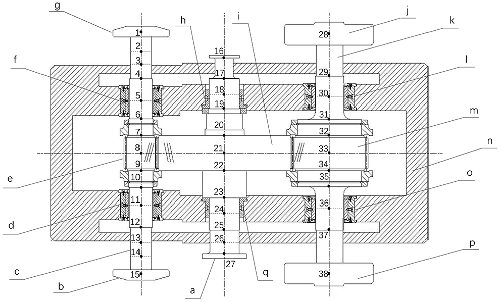
Finite element model of triple-gear-rotor system: (a) rotor 3, (b) disk 1, (c) rotor 1, (d) bearing 1, (e) gear 1, (f) bearing 2, (g) disk 2, (h) bearing 6, (i) gear 3, (j) disk 4, (k) rotor 2, (l) bearing 4, (m) gear 2, (n) gearbox, (o) bearing 3, (p) disk 3, and (q) bearing 5.
Support stiffness and damping of triple-gear-rotor system.

The mathematical model of the triple-gear-rotor system obtained as follows:

where
Model of nonlinear factors of triple-gear-rotor system
The triple-gear-rotor system has two gear pairs, which are modeled as shown Figure 2. The degrees of freedom of the gear pairs are

where

Model of the helical gear pair.
Denote the constant backlash of each gear pair along meshing direction as

where

where
The equations (3) and (4) show the gear tooth are in direct contact when
The International Organization for Standardization (ISO) proposed a method to calculate the meshing stiffness and damping, 24 which allows expressing the meshing stiffness of a single pair of gear teeth as follows:

where
For helical gears with the helix angle of no more than

where
Considering the periodic fluctuation of meshing stiffness, Kahraman et al., 3 proposed to expand the time-varying meshing stiffness of gear pair into a Fourier series. Keeping only the first harmonic, it can be expressed as follows:

where
Meshing damping of the gear teeth can be calculated by method of damping ratio, which is expressed as follows:

where
The calculation results of meshing stiffness and damping are shown in Figure 3.

Meshing stiffness and damping: (a) meshing stiffness of gear pair 1, (b) meshing damping of gear pair 1, (c) meshing stiffness of gear pair 2, and (d) meshing damping of gear pair 2.
The power load of CAES acting on the triple-gear-rotor system in the form of torque load, which can be expressed as


Where
The excitation forces at the nodes of the gear pairs is defined as

where
Unbalanced excitation should be applied to every node of the model because unbalance excitation is in every part of the system. The expression for the unbalance excitation is as follows:

where
Table 2 shows some key parameters of the helical gear pair model.
Parameters of helical gear pairs.

Numerical solution
This paper uses the software of MATLAB to solve the mathematic model by Newmark step-by-step integration method.
Experiment
Structure of triple-gear-rotor test bench
A triple-gear-rotor test bench was built according to the structure and size of the triple-gear-rotor system in CAES, which is shown in Figure 4, and the physical picture of the gearbox for experiment is shown in Figure 5. A variable-frequency motor with rated power of 315 kW and rated speed of 3500 rpm is used to drive the speed-increasing gear box, and its growth ratio is 2.7. The speed increasing gearbox has no critical speed in the rated speed range of the variable frequency motor. The speed-increasing gearbox is used to drive rotor 3, and rotor 3 is used to drive rotor 1 and 2. The load is transmitted through a flexible coupling among the power system, speed-increasing system and experimental system to achieve the effect of vibration filtering. A radial displacement sensor connected to a computer is used to measure and store the lateral vibration displacement of the rotors. In this paper, the positions of the vibration observation points in mathematical model are consistent with the installation position of the sensors in the test bench.

Triple-gear-rotor test bench.

Experimental gearbox.
Verification of mathematical model
Rotor 1 has disks on its both ends and its rotating speed is much higher than that of rotor 2 and 3, therefore, the experimental results and the simulated results of rotor 1 are selected to verify the accuracy of the mathematical model. Figure 6 shows the first-order critical speed of rotor 1 obtained numerically is about 14,000 rpm, and the experimental result is about 14,500 rpm. The difference between the numerical and experimental result is about 3.3%, therefore the mathematical model is relatively accurate.
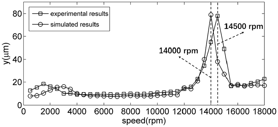
Comparison of experimental and numerical results.
Results
In this section, the responses of rotor 1, 2, and 3 are analyzed. The motion states are analyzed using bifurcation diagrams of the lateral vibration, the distribution of acceleration in frequency domain is analyzed using 3-D acceleration spectrum, the meshing states are analyzed using time domain diagrams of meshing force. The specific parameters used in this study are those of a triple-gear-rotor system in CAES with power level of 10,000
Response of rotor 1 under effects of variable torque load at rated speed
Figure 7 shows the bifurcation diagram of rotor 1 with the torque load as the control parameter in the range of 0-4775

Bifurcation diagram of rotor 1.
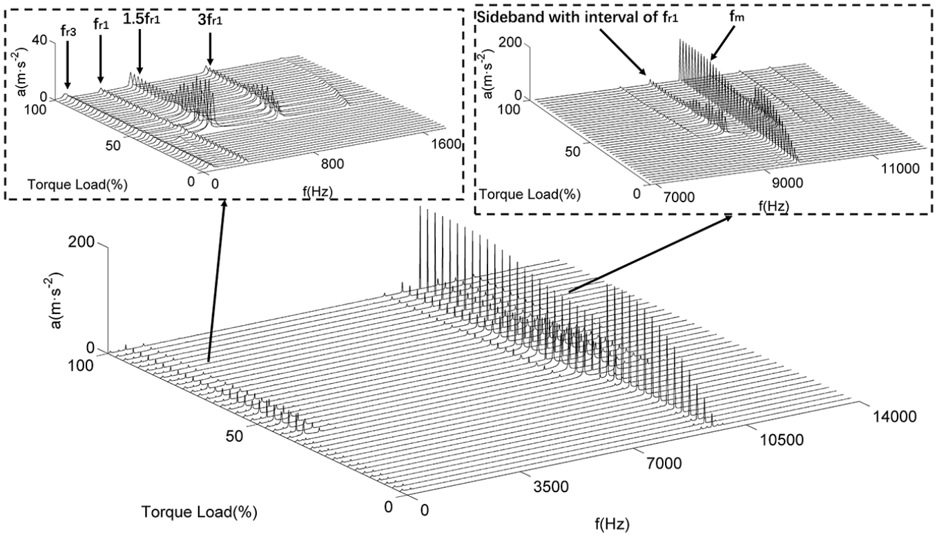
To further analyze the applied force of rotor 1 in the frequency domain, a 3-D acceleration spectrum with the torque load as the control parameter in the range of 0–4775

3-D acceleration spectrum of rotor 1.
Figure 9 shows rotor 1 exhibits tooth separation in the whole range of torque load, and the meshing force fluctuation is not obvious when the torque load is light, the meshing force fluctuates violently when the torque load is heavy. In addition, the amplitude of meshing force increased in the whole range of torque load. Because the unbalanced excitation is independent of variable torque load according to equation (12), the meshing force can reflect the variation of the applied force of rotor 1. Therefore the violent fluctuations of meshing force and the increasing amplitude of meshing force can explain the variable trend of 3-D acceleration spectrum, then the reason for the response of rotor 1 tending to chaotic above 40% of the torque load is thoroughly explained.
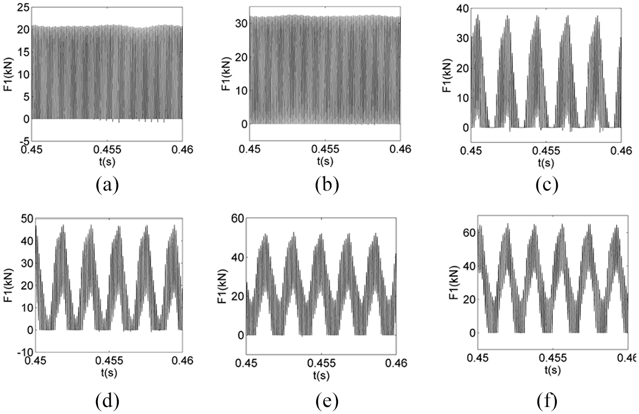
Meshing force of rotor 1 at: (a) 15% torque load, (b) 30% torque load, (c) 45% torque load, (d) 60% torque load, (e) 75% torque load, and (f) 90% torque load.
Response of rotor 2 under effects of variable torque load at rated speed
In Figure 10, the bifurcation diagram of rotor 2 with the torque load as the control parameter in the range of 0–11,525

Bifurcation diagram of rotor 2.
Figure 11 shows the acceleration at

3-D acceleration spectrum of rotor 2.
Figure 12 shows the meshing force fluctuation is not obvious when the torque load is light, but it fluctuates violently when the torque load is heavy. Similarly, the meshing state of rotor 2 is tooth separation when the torque load is light, but separation disappears when the torque load is heavy. In addition, the amplitude of meshing force increases in the whole range of torque load, which is similar to rotor 1. Also similar to the analysis of rotor 1, the periodic weakening of the response of rotor 2 after 40% of the torque load is thoroughly explained by the violent fluctuation of meshing force and the increasing amplitude of meshing force.

Meshing force of rotor 2 at: (a) 15% torque load, (b) 30% torque load, (c) 45% torque load, (d) 60% torque load, (e) 75% torque load, and (f) 90% torque load.
Responses of rotor 3 under effects of variable torque load at rated speed
Figure 13 presents the bifurcation diagram of rotor 3 with the torque load as the control parameter in the range of 0–21,240

Bifurcation diagram of rotor 3.
The applied force of rotor 3 is analyzed using the same method as for rotor 1. From the enlarged view of Figure 14, one can find that the acceleration at
3-D acceleration spectrum of rotor 3.
Figure 15 shows the meshing force fluctuation is not obvious when the torque load is light, but it fluctuates violently when the torque load is heavy, and the amplitude of meshing force increases in the whole range of torque load. Because the meshing force of rotor 3 is the sum of the meshing force of rotor 1 and 2, it cannot reflect the meshing state of rotor 3, and the meshing state of rotor 3 is the superposition of the meshing states of rotor 1 and 2. Because the unbalanced excitation is independent of the variable torque load according to equation (12), the meshing force can reflect the changes of the applied force of rotor 3. Therefore the periodic weakening of the response of rotor 3 after 40% of the torque load is thoroughly explained by the violent fluctuations of the meshing force and the increasing amplitude of meshing force.

Meshing force of rotor 3 at: (a) 15% torque load, (b) 30% torque load, (c) 45% torque load, (d) 60% torque load, (e) 75% torque load, and (f) 90% torque load.
From the above analysis, one can conclude that the responses of rotor 1, 2, and 3 are generally similar. Because the acceleration distribution in the frequency domain can reflect the distribution of applied force in the frequency domain, the similarity in the response of the three rotors can be explained by the similarity in their acceleration distributions in the frequency domain. equation (12) shows unbalanced excitation does not change with the varying torque load, therefore the similarity in the meshing force of rotor 1, 2, and 3 can explain the similarity in the acceleration distribution of the rotors in the frequency domain. The similarity of the meshing force and meshing state of rotor 1, 2, and 3 is considered as the basic reason for the similarity of the responses of the three rotors, which reflects the coupling effects of the gear pairs making the responses of multiple rotors similar.
Conclusion
A finite element model for the key equipment of CAES – the typical triple-gear-rotor system was established, and an experiment was carried out to verify the accuracy of the mathematical model. The dynamic characteristics of the system operated under a wide range of variable torque loads at a high rotating speed were studied in detail. The most notable results can be summarized as follows:
The dynamic response of the triple-gear-rotor system in CAES has two stages when the system is subjected to large-scale torque load lifting at a high rotating speed: the system response is relatively strongly periodic when the torque load is light, but tends to be chaotic when the torque load is heavy. Transition between the two states is relatively short and violent. The variation in the dynamic characteristics of triple-gear-rotor system with torque load may be used for the selection of operation range of the multi-gear-rotor systems for CAES.
The frequency components of the system acceleration also appears in two stages when the system is subjected to large-scale torque load lifting at a high rotating speed: The system acceleration in the frequency domain is mainly composed of rotation frequency and meshing frequency when the torque load is light, and then the side-band-frequencies around the meshing frequency and the multiples of the rotating frequency are generated at high torque loads. The distribution of the system acceleration in frequency domain can explain the variation in the system response with torque load.
The analysis of meshing force shows that when the frequency-domain components of system acceleration become complex, the meshing state of the gear pair will change, or the meshing force will fluctuate violently, which is considered as the basic reasons for the variation of system response with the torque load.
The three rotors in the triple-gear-rotor system studied show a strong similarity in the meshing state and meshing force fluctuation, which result in the similarity in the dynamic responses of the three rotors. This is considered to be the confirmation of the dynamic coupling effect of the gear pairs. The similarity in the dynamic response of the three rotors in triple-gear-rotor system may help to simplify the process of judging the overall dynamic characteristics of the engineering multi-gear rotor system.
Footnotes
Declaration of conflicting interests
The author(s) declared no potential conflicts of interest with respect to the research, authorship, and/or publication of this article.
Funding
The author(s) disclosed receipt of the following financial support for the research, authorship, and/or publication of this article: This study was funded by the National Key R&D Plan (Grant No. 2017YFB0903605), the National Natural Science Foundation of China (Grant No. 51976218), the International Partnership Program, Bureau of International Cooperation of Chinese Academy of Sciences (Grant No. 182211KYSB20170029), Guizhou Province Large Scale Physical Energy Storage Engineering & Technology Research Center program ([2017]07), and Guizhou Province Large Scale Physical Energy Storage Engineering Research Center program ([2017]951).