
Abstract
During the construction and assembling stages of shield tunnels, the ellipticity of segment assembly, and the angle between segments are the main reasons for joint leakage of shield tunnel. In this paper, taking Chengdu Metro shield tunnel as the research background, the relationship between assembling ellipticity and segment opening angle is obtained by geometric calculation, and the waterproof effect of gasket under different segment joint angle is studied by finite element analysis method. Results of the nonlinear numerical analyses, there is a linear positive relationship between the opening angle of segments and the ellipticity degree. Meanwhile, the different side joint opening angles of the segments have different effects on the waterproof effect of the gasket, which is manifested as the external angle is greater than the internal. Based on the above research results, this article can provide some references for the design, production, processing, and quality inspection of shield tunnel gasket in the future.
Introduction
The shield has been extensively applied to construct underground tunnels due to its various advantages such as high flexibility, low resource consumption, high tunneling efficiency, and minimal environmental disturbance. And the lining structure of the shield tunnel consists of the multitudinous segmental rings in the longitudinal direction of the shield tunnel. Longitudinal adjacent segment rings of shield tunnel and the segment joint in the circumferential direction are permanently connected by the longitudinal and the circumferential bolts, form the longitudinal and annular joint.1–8 However, there is discontinuous interface called the segmental joint1,2,9–12 between the adjacent segments. Segmental joints are greatly fragile parts of the lining structure in shield tunnels, 13 including the structural (lower stiffness compared to main segments) and non-structural (potential water leakage points) subordinates.14,15 After assembly, there are often open angles between the segments, and most of the time, the segments assembled into rings are not standard circles but ellipses. Once both the opening angle and the ellipticity degree of segments are not properly controlled, the segment of shield tunnel will suffer from water leakage,13,14,16–18 which threatens the operation safety. 19 Therefore, it is very important to control the ellipticity of segment assembly and the assembling accuracy of segment angle.
Previous works mainly focused on the structural behavior of segmental joints,1–3,7,20–23 rather than the sealant behavior by the ellipticity of segment assembly and the assembling accuracy of segment opening angle. In the current tunnel engineering, EPDM rubber gaskets are often installed at the joints of the pipe segments. Its porous design can reduce the compressive stress during assembly, and has good compressive stress relaxation resistance, which can extend the service life. The sealing effect can be achieved by squeezing two gaskets. If the waterproof resistance produced by squeezing the two gaskets is less than the external water pressure, the waterproofing can be considered as invalid. During the assembling process of shield segments, the attitude of shield machine, the position of the top block segment and the degree of construction specification all affect the segment assembly accuracy, cause the staggering, opening, and angle opening conditions at the joints, which will affect the contact state between the gaskets, the size of the waterproof resistance, and then affect the waterproof performance of the gasket. The waterproof failure of the gasket causes water leakage in the tunnel, which to a large extent leads to changes in the internal force of the tunnel, resulting in ground settlement, threatening the safety of operation.1,2 In this paper, the non-linear numerical simulation method is used to analyze the sealing effect of segment joint under the conditions of opening and staggering.3–5 On this basis, the waterproof pressure of opening and staggering gasket joints was studied through experiments.9,10 Beam element model was used to analyze the opening angle of segment joint under different segment assembly ellipticity.20,21,23
Summarizing the above literature, it is found that there are few studies on the waterproof performance of gaskets in the case of opening angle. In previous analysis models, only the upper and lower gaskets and the groove part of the segment were considered, did not consider the influence of the thickness of the segment and the groove position on the waterproof performance, and the influence of the two was manifested by the opening angle of the inside and outside. In this study, the waterproof performance of sealing gasket is studied from the ellipticity of segment assembly and the assembly precision of segment opening angle. In the analysis, the predecessor’s model is consistent with the actual project when the operating conditions are opened and staggered. However, in the analysis of the opening angle, the above model can only set a specific opening angle value, ignoring the influence of the groove position on the waterproof, which is not in accordance with the actual project. Based on the previous models, this study added the internal and external opening angles to the waterproof evaluation of gaskets. Taking Chengdu metro shield tunnel as an example, this paper analyzes the relationship between assembly ellipticity and segment opening, and obtains the range of segment connection angle under different ellipticity. The waterproof effect of gaskets with different joint openings was studied by finite element analysis.
Project overview
Chengdu area has the geological characteristics of water-rich sandy cobbles. As the research object of this article, the Chengdu Metro Line 18 project has the characteristics of high groundwater level and strong stratum permeability. The longitudinal slope of the interval tunnel is 2‰–24‰. The maximum buried depth of the line is about 38 m, and the minimum plane curve radius is 500m. The maximum possible water head height of this project is 33.37 m, design the safety factor is 2, and the fortification pressure is 0.7 MPa. The lining is made of reinforced concrete segments with a ring width of 1500 mm, with an inner diameter of 7500 mm and an outer diameter of 8300 mm. The segment structure diagram is shown in Figure 1. For the convenience of research, the number of segments is shown in Figure 2. The segment assembly method adopts “4 + 2 + 1” staggered assembly, 19 segment assembly points are also shown in Figure 2. The distance between the gasket groove and the outer ring of the segment is 57.5 mm, and the groove area is 550.312 mm2. The gasket is located in the segment groove shown in Figure 3. The gasket is made of elastic rubber material, and the dimensions are shown in Figure 4. The blue hole of the gasket shown in Figure 4 is a closed hole, and the red hole is an open hole. The net area of the gasket is 533.33 mm2, the opening ratio is 0.398, and the average Shore hardness is 65. The data of washer groove and washer are provided by manufacturer.

Segment structure.

Segment number and assembly points.

Segment groove (mm).

Sealing gasket dimensions (mm).
The relationship between ellipticity and opening angle
Calculation method
Generally, the assembly work of the segments is carried out under the protection of the shield shell, so only the gravity of the segments acts on the segments after the assembling. When the segments are not closed into a ring, it can be assumed that no bending moment is transmitted between the segments. Especially for staggered assembly, the concave–convex tenon between the rings has a great restraining force on the segments in this time, it can be assumed that the bolts between the segments at this time are only tightened in accordance with the assembly trend of the upper ring segments. From this point of view, it can be assumed that there is no bending moment transfer between the segments during the segment assembly to the shield tail ejection, which is equivalent to assuming that the segments are hinged. Considering the geometric dimensions of the segments and the contact relationship between the segments, two types of opening angles are inevitably produced during assembly, namely, the inner and outer opening angles emphatically studied in this paper. Assuming that there is no dislocation deformation between the segments when the opening angle of the segment joints occurs, the opening angle generated at the segment joints at this time must take one end of the seam as the fulcrum, then the fulcrum can be set as a “hinge” connection. When the outer opening angle is generated, the joints of the inner arc surface of the tunnel are hinged; when the inner opening angle is generated, the joints of the outer arc surface of the tunnel are hinged, and the hinge point setting is shown in Figure 5.

Opening angle calculation model.
The horizontal and vertical ellipse are simulated by the forced displacement direction in the horizontal and vertical directions, and the ellipticity of the assembly is simulated by the displacement magnitude. When simulating a horizontal ellipse, the Y direction converges toward the inside of the tunnel, and the X direction converges toward the outside of the tunnel; when simulating a vertical ellipse, the reverse is true, and the horizontal and vertical ellipses are shown in Figure 6. The forced displacement parameters are calculated from the ellipse direction, ellipticity, and tube size. As shown in Figure 7, by reading the coordinates of the three points on the two sides of the deformed joint, the joint opening angle can be directly calculated using the geometric relationship.

Horizontal and vertical ellipse conditions.

Inner and outer opening angle.
As shown in Figure 2, this project includes 19 assembly points, the 1st and 18th points are often used on site, and this article only uses these two points as working conditions. Regarding the assembly ellipticity, the national standard requires less than 5±‰D. Five ellipticity calculation models of segment as shown in Figure 5 are set up to analyzed the relationship between the segments ellipticity and the opening angle: 2‰D, 4‰D, 6‰D, 8‰D, 10‰D.
Calculation results
The calculation result of the relationship between the joint opening angle and the ellipticity is shown in Figure 8, where (A) point is 1 vertical ellipse condition (B) point is 1 horizontal ellipse condition (C) point is 18 vertical ellipse condition (D) point is 18 horizontal ellipse condition. In Figure 8, L1–L2 represents the joint between the segments, and other numbering forms are similarly deduced. In Figure 8, below the red discontinuous line is the inner opening angle (the inner side of the segment ring is opened), and above the red discontinuous line is the outer opening angle (the outer side of the segment ring is opened).

The relationship between joint opening angle and ellipticity. (a) Vertical ellipse condition of Point 1, (b) horizontal ellipse condition of Point 1, (c) vertical ellipse condition of Point 1, (d) horizontal ellipse condition of Point 18.
When the assembly point and the deformation are the same, the opening angle between the joints of the specific segments has a linear relationship with the ellipticity, which is equivalent to the value (absolute value) of the opening angle increases as the ellipticity increases. The opening angle attributes (vertical ellipse, horizontal ellipse) of the segment joints do not change with the ellipticity, and the attributes of the opening angle are opposite in the case of horizontal and vertical ellipse. The range of the opening angle under various ellipticity conditions of 0.0166°–0.3467° (2‰), 0.0771°–0.6884° (4‰), 0.1248°–1.0523° (6‰), 0.1816°–1.4106° (8‰) ), 0.2414°–1.7736° (10‰), respectively. Figure 9 show the maximum and minimum opening angle values under the above ellipticity values. It can be found from Figure 9 that the maximum and minimum opening angle are positively correlated with the opening angle, and the increase rate of the maximum value is greater than the minimum. According to analysis, in the same ellipticity, the smaller the radius of curvature of the joint of a segment, the larger the opening angle. With the increase of ellipticity, the radius of the joints of the segments with small curvature radius will be further reduced, while the radius of the joints of the segments with large curvature radius will not change significantly, causing the difference between the maximum value and the minimum value to become larger and larger.

The maximum and minimum opening angle value changes with ellipticity of segments.
Evaluation of waterproof effect under different opening angles
Calculation method of gasket waterproof effect
Material model
The research object of this article is EPDM rubber gasket, Which is a kind of hyperelastic material with strong deformation ability, Mooney–Rivlin model can well simulate the constitutive relationship of this kind of special rubber, a large number of simulation results and test comparisons prove that it can meet the actual requirements, so the Mooney–Rivlin model is used for the rubber constitutive from Figure 10. Figure 10 shows the contact state of two gaskets at the joint between the segments after assembly. Among them, the values of the parameters C10 and C01 required in the numerical analysis are determined by the rubber hardness (HA). Investigation of the currently successfully operated subway shield tunnels and large cross-river tunnels, the results are listed in Table 1. It can be seen that the hardness index of the gasket is mostly between 60° and 70°, and the fluctuation is mostly 5°. In this paper, the gasket hardness takes the intermediate value of 65°, and the values of parameters C10 and C01 are calculated by referring to the method introduced by Gong et al. 3 It is calculated that C10 is 0.592 and C01 is 0.148. The dimensions of the sealing groove and gasket have been marked in Figures 3 and 4. Figure 11 shows the opening angle analysis model. Two reference points in the inner opening angle analysis model are set at the outer end of the segment, as shown in Figure 11(a). Two reference points in the external opening angle analysis model are set at the inner end of the segment, as shown in Figure 11(b). When analyzing each working condition, the two gaskets and segments of the model are rotated in opposite directions, that is, the upper and lower gaskets and segments rotate half the opening angle around the reference point, so as to reduce the influence of the initial assembly of the model on the analysis results.

Numerical analysis model of sealing gasket.
Hardness of gaskets in domestic projects.


Opening angle analysis model: (a) analysis model of internal opening angle and (b) analysis model of external opening angle.
Model meshing
The triangular meshing method is used as the meshing method of the gasket in this study. This study contains a large number of analysis conditions. Using this method can not only reduce the influence of grid size and grid distribution on the calculation, but also greatly reduce the numerical analysis time. A single gasket is divided into 1918 grid elements, and the size of each grid cell is about 0.278mm2.
Boundary states and loading steps
In Figure 11, there are two kinds of nonlinear boundary state problems, one is the contact between flexible body and rigid body, the other is the contact between flexible body and flexible body. For the gasket in the groove of the tube segment, it will produce a larger displacement after being compressed. Not only the contact problem of the coupling surface between the tube segment and the contact wall, but also the contact of the upper and lower gaskets and the gasket itself must be considered. Since the groove is in concrete, its stiffness is much greater than that of the rubber gasket, hence, a rigid-flexible contact is set between the segments and the sealing gasket, and a flexible–flexible contact is set between the sealing gaskets. The compression problem of the gasket is simplified as a plane strain problem. In order to improve the calculation efficiency, the groove is used as an analytical rigid body to simulate its constraint on the gasket.
Two loading steps are considered in the model, including the initial contact phase and the segment assembly phase (setting the external and internal opening angles). According to the calculation and analysis in Section 3, the opening angle corresponding to 6‰D ellipticity ranges from 0.1248° to 1.0523°. In order to study the waterproof effect under different opening angles, this paper sets up 6 kinds of opening angle values: 0.2°, 0.4°, 0.6°, 0.8°, 1.0°, and 1.2° working conditions. In addition, two working conditions of the inner opening angle and the outer opening angle are also set.
Calculation results and analysis
The values of the opening angle are shown in Figure 12. It can be seen that the distribution trend of the contact pressure between the gaskets in the six working conditions with an external opening angle of 0.2° to an external opening angle of 1.2° is highly consistent with the completely closed state, and all the contact pressure distribution presents a double “W” shape. It can be analyzed from Figure 12 that the fewer holes in the vertical direction of the contact surface with the gasket, the higher the “wave crest” (the greater the contact pressure). Furthermore, it can also be seen from Figure 12 that with the increase of the external opening angle in the “wave crest” area, the peak value of the “wave crest” gradually decreases, that is, a negative correlation; in the “trough” area, with the external opening angle increasing, the peak of the “trough” is gradually rising, that is, showing a positive correlation.
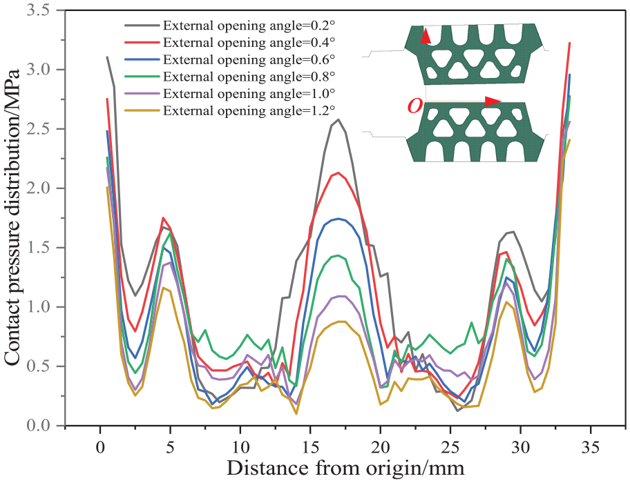
Contact pressure distribution between external opening angle gaskets.
As it can be seen from Figure 13, the “peak” and “valley” change characteristics of the contact pressure distribution curve of the inner opening angle as same as the outer. Note that although the “wave crest” and “trough” of the curve change with the inner opening angle, the inner opening angle curve is relatively tight, and the change range of “wave crest” and “trough” is smaller than that of the outer opening angle. The inner opening angle has little effect on the closing compression force of the gasket, and the possible reason is that the gaskets is close to the rotation origin of the inner opening angle, and the change of the opening angle has little effect on the opening between the gaskets (relative to the fully compressed state).

Contact pressure distribution between inner opening angle gaskets.
In order to analyze the waterproof ability of the rubber gasket under different expansion states and six working conditions with an opening angle of 0.2°–1.2°, use the average contact pressure between the gaskets evaluate the influence of the opening angle on the waterproof ability of the rubber gasket. In the two cases of the external opening angle and the internal opening angle, the average contact pressure of the different opening angles between the gaskets is calculated, and then visualized the result to obtain Figures 14 and 15. The red broken line in the Figures 14 and 15 is the design waterproof pressure of 0.7MPa.
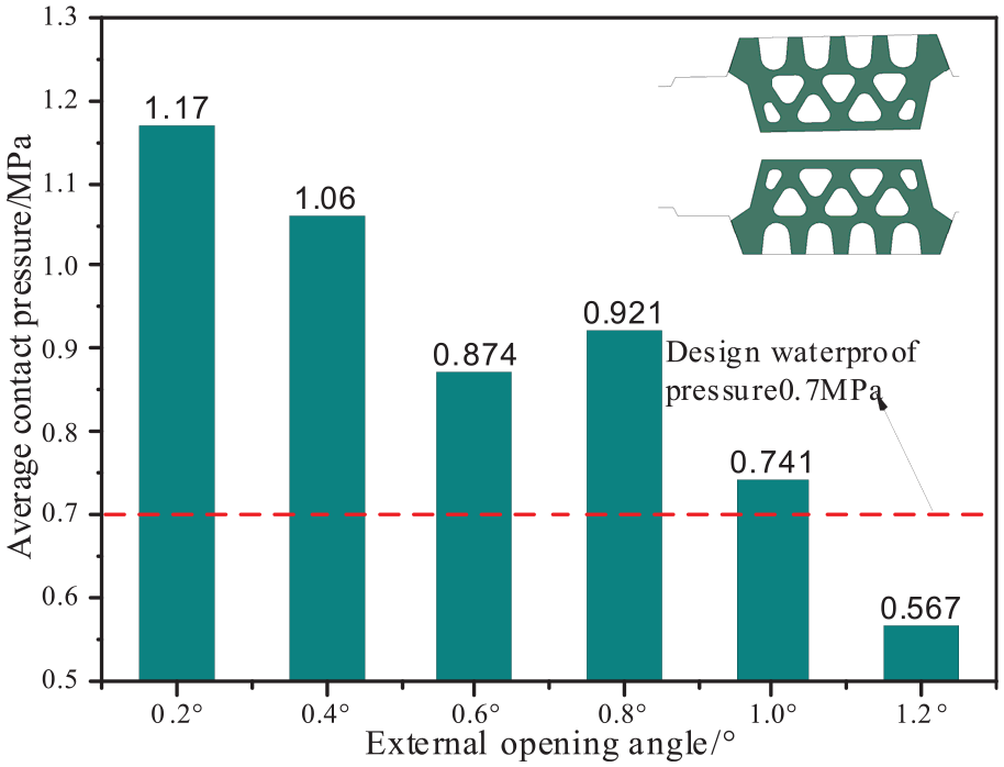
Average contact pressure distribution between external opening angle gaskets.

Average contact pressure distribution between inner opening angle gaskets.
It can be seen from Figure 14 that in the case of the external opening angle, the maximum average contact pressure between the gaskets is 1.17MPa at 0.2°; the minimum is 0.567MPa at 1.2°. According to the national standard requirement of the assembly ellipticity of 5‰D, the corresponding opening angle is less than 1.0°, so the assembled ellipticity of 5‰D meets the design waterproof pressure. At the same time, it is noted that the pressure value corresponding to the opening angle of 0.8° is not stable. The reason is that with the increase of the opening angle, the originally closed hole in the gasket suddenly opens, which leads to the close contact of the gasket again and generates a large pressure value. However, when the opening angle continues to increase, the effect will disappear and the pressure will continue to decrease.
It can be seen from Figure 15 that at the internal opening angle of 0.2°–1.2°, the maximum average contact pressure between the gaskets is 1.45MPa and the minimum is 1.17MPa, which meets the design waterproof pressure within the range of the set angles. At the same time, it is noted that the average contact pressure also shows an increasing trend at the angle of 1.2° (compared with the increase at the angle of 1.0°). The reason is that when the model rotates between 1.0° and 1.2°, the gasket close to the inside is gradually separated, and the gasket close to the outside is gradually compressed, and the influence of compression is greater than that of separation, causing the pressure to rise.
In summary, the average contact pressure between the gaskets decreases with the expansion of the opening angle. However, when the external opening angle is 1.2°, the design requirements are not met from Figure 14. According to the change trend of the average contact pressure between the gaskets and the linear change law of the opening angle in the previous section, the maximum and minimum opening angles are linear with the increase of the opening angle. The corresponding opening angle of assembly ellipticity 5‰D required by the national standard is 0.870°, combined with Figure 15, it is found that the assembled ellipticity of 5‰D meets the design waterproof pressure.
Conclusion
In this paper, a subway shield tunnel in Chengdu is taken as the research background, the relationship between assembly ellipticity and segment opening angles is analyzed, and then the waterproof effect of the gasket under different opening angles is analyzed. The main conclusions are as follows:
There is a linear positive correlation between the opening angle of the segment joints and the ellipticity; the opening angle attribute of the segment joint does not change with the ellipticity, and in the case of horizontal and vertical ellipse, the attributes of the opening angle are opposite. The maximum and minimum values of opening angle range increase linearly with the increase of opening angle under each ellipticity condition. The reason is that in the same ellipticity, the smaller the radius of curvature of the joint of a segment, the larger the opening angle. With the increase of ellipticity, the radius of the joints of the segments with small curvature radius will be further reduced, while the radius of the joints of the segments with large curvature radius will not change significantly, causing the difference between the maximum value and the minimum value to become larger and larger;
According to the distribution of contact pressure and the average contact pressure, the influence of the opening angle on the waterproof effect of the gasket is that the external angle is greater than the inner angle. The inner opening angle has little effect on the closing compression force of the gasket, and the possible reason is that the gaskets is close to the rotation origin of the inner opening angle, and the change of the opening angle has little effect on the opening between the gaskets (relative to the fully compressed state). It is also found that when the ellipticity is greater than 5‰D, the gasket of this project will not meet the waterproof design requirements, so the assembly ellipticity must be strictly controlled during construction.
Although the relationship between ellipticity and opening angle is summarized in this paper, there is no numerical quantitative analysis. In order to better guide the design and construction, we hope that readers can do further research from the numerical quantification.
Footnotes
Author’s contribution
ZJ proposed the original idea for the Mechanical behavior of sealed waterproof for shield tunnel segment joint under different assembling ellipticity. GS wrote the main manuscript text and accomplished the numerical simulation. CY prepared all the tables and all the figures. All authors reviewed the manuscript.
Author’s note
The corresponding author is responsible for submitting a competing interest statement on behalf of all authors of the paper. This statement must be included in the submitted article file.
Declaration of conflicting interests
The author(s) declared no potential conflicts of interest with respect to the research, authorship, and/or publication of this article.
Funding
The author(s) disclosed receipt of the following financial support for the research, authorship, and/or publication of this article: This paper was supported by the Basic Applied Research Projects of Sichuan Science and Technology Department, No. 2019YJ0349.
Data availability
The data used to support the findings of this study are included within the article.