
Abstract
In aircraft manufacturing, the vertical accuracy of connection holes is important indicator of the quality of holes making. Aircraft products have high requirements for the vertical accuracy of holes positions. When drilling and riveting are performed by an automatic robotic system, assembly errors, bumps, offsets and other adverse conditions, can affects the accuracy of manufacturing and detection, and in turn the fatigue performance of the entire structure. To solve this problem, we proposed a technology for detecting the normal-direction based on the adaptive alignment method, built a mathematical model for posture alignment, and studied the calibration method and mechanism of the detection device. Additionally, we investigated techniques for error compensation using an electronic theodolite and other devices when the adaptive method is used for detection. In verification experiments of the method, multiple sets of results demonstrated that the key technical indicators are as follows: normal accuracy <0.5°, average deviation after correction =0.0667°. This method can effectively compensate the errors affecting hole making work in automated manufacturing, and further improve the positioning accuracy and normal-direction detection accuracy of the robot.
Keywords
Introduction
With the development of large domestic aircraft projects, there is an urgent need for research on automatic drilling and riveting technology and independent research and development of equipment. 1 The developed countries in the aviation industry have mature automatic drilling and riveting technology, and have companies that can manufacture the requisite equipment, such as the U.S.A.’s GEMCOR (C type automatic drilling and riveting system) and Germany’s BROETJE-AUTOMATION (C type and D type automatic drilling and riveting systems). 2 BROETJE-AUTOMATION conducts research on robotic drilling and riveting technology, 3 and its RACE automatic drilling and riveting system has performed well in applications by improving the positioning accuracy using the surface-normal detection method and the reference plane detection method. In 2019, FILL of Germany unveiled the ACCUBOT automatic drilling and riveting robot, a computerized numerical control (CNC) 7-axis robot that moves the end effector to the drilling position provided by the post-processor, and can be readjusted if necessary. Aircraft factories, research institutes, and universities in China have cooperated vigorously in recent years.4–10 For example, Chengdu Aircraft Group, Xi’an Aircraft Group, Northwestern Polytechnical University, Nanjing University of Aeronautics and Astronautics, and others have carried out research on automatic drilling and riveting systems. The Maozhen Gong’s team of Beijing University of Aeronautics and Astronautics used a laser ranging sensor to adjust the robot’s hole-making posture to intelligently adjust the verticality of the end of an aerial hole-making robot. 11 The laser ranging sensor is based on three-dimensional (3D) laser scanning detection, in which the laser scanning data are compared to point cloud data determined by the surface-normal method to ensure high detection accuracy. However, the 3D laser scanning method is limited by the sampling speed, which makes it difficult to use for real-time monitoring of high-speed riveting work, and can only be used as an offline detection method. Elsewhere, Qiang Zhan and Shusheng Bi’s team developed a set of hand–eye calibration and positioning methods for robotic hole-making in aircraft wall panels. 12 The methods use the relationship between the camera coordinate system and the scene coordinate system to indirectly obtain the hand–eye relationship. The robots use the calibrated hand–eye relationship for positioning, describing the position of the target point in the robot coordinate system, and providing navigation information for the robotic hole-making system. Shenyang Aircraft Industry (Group) Co., Ltd. has developed a robotic hole-making system for automatic hole-making in aircraft components. 13 Through the visual inspection system, the required hole-making position information can be provided to the host computer and the robot controller. At the same time, the weld can be detected and the positional relationship between it and the required hole-making can be measured. The working component of the vision system is a workpiece with a regular plane. Based on this, a hand–eye calibration algorithm based on a two-dimensional plane work was formulated.
In such systems, the detection accuracy of the normal direction and the calibration accuracy of the sensor determine the verticality of the hole-making, which is one of the most important indicators of the hole-making performance. 14 However, when the robot is equipped with sensors and works online in-situ, there will inevitably be installation errors, bumps, and offsets. These problems seriously affect the accuracy of hole positioning, which in turn compromises the accuracy of assembly and the fatigue performance of the entire structure. Therefore, how to improve the detection accuracy of the normal direction in an automatic drilling and riveting system through online methods for error compensation, and thus enhance the positioning accuracy of the connection hole, has become an important research direction.15–18
Materials and methods
At present, before drilling and riveting procedures for aircraft assembly, it is first necessary to measure, in real time, with the help of displacement sensors and other equipment, the actual normal direction of the small local area to be drilled, and then adjust the corresponding joint angle of the robot to change the axis direction of the end effector spindle. 19 To accomplish the above tasks, in this paper an adaptive method is proposed to correct the normal direction, which can effectively compensate for a series of errors that occur in the sensor assembly, therefore improving the positioning accuracy, and allowing the requirements on the vertical accuracy of the connecting hole to be met.
Geometric model
A normal-direction positioning system for robot drilling and riveting is established. The purpose is to convert the known information detected by the laser sensor into a mathematical model for the robot to accurately adjust the posture (a′, b′, c′). Through mathematical models, the system converts the detected distance information into the angle data (θ1, θ2, 0) of the indenter axis and the normal of the point to be tested in the tool coordinate system, then converts the angle data into the precise posture coordinates of the robot (a′, b′, c′), thus achieving high-accuracy object-normal calibration to improve the accuracy of normal detection.
The ultimate goal of robot posture alignment is to ensure that the position of the virtual tool tip point remains unchanged; the axis of the indenter must be consistent with the outward normal direction of the point to be tested on the surface of the cover. 20 As shown in Figure 1(a), to find a positive model for the posture, the geometric measurement zero points of the four laser sensors are P1, P2, P3, and P4. The projection points of the four laser sensors on the surface of the cover are Q1, Q2, Q3, and Q4. In this model, the plane P1Q1P2Q2 and the plane P3Q3P4Q4 are required to be perpendicular to each other. If the vertical condition is not met, the precise angle between the two planes should be measured; the intersection of plane P1Q1P2Q2 and plane P3Q3P4Q4 should be the indenter axis, denoted OT. Let the external normal vector of the local tiny plane Q1Q2Q3Q4 at the test point T be TH, where point H is a point on the plane P1P2P3P4, while the angle between the axis of the indenter and the normal direction from the point to be tested on the surface of the cover is θ. When performing normal detection, let the four displacement sensors measure the distances between P1 and Q1, P2 and Q2, P3 and Q3, and P4 and Q4, namely P1Q1 = h1, P2Q2 = h2, P3Q3 = h3, P4Q4 = h4. The installation dimensions are set to P1P2 = l12 and P3P4 = l34. After the sensor reading is completed, the serial port server is used to input the values h1, h2, h3, and h4 into the system control software for subsequent calculations. In the plane P1P2P3P4, the straight line HN is made parallel to the Z′ axis of T–x′y′z′ and intersects the straight line P3P4 at point N. Meanwhile, the straight line HM is parallel to the Y′ axis of T–x′y′z′ and intersects the straight line P1P2 at point M. Then, line segment TN is the projection of line segment TO on the X′TY′ coordinate plane of T-x′y′z′, and line segment TM is the projection of line segment TO in the X′TZ′ coordinate plane of T-x′y′z′. Let the angle from TO to TN be θ1, the angle from TO to TM be θ2, and the angle from TM to TN be t1. The spatial relationship between θ and θ1, θ2, t1 can be seen in Figure 1(a). θ is the angle between the straight lines TO and TH, whose value is constant, and θ1, θ2, t1 are all angles between the vectors, with positive and negative values. The rotation direction θ1 around the T–x′y′z′ axis is specified as the positive direction, the direction of rotation around the T–x′y′z′ axis is θ2 in the negative direction, and the sign of t1 is consistent with θ1.The projection relationship in the X′TZ′ coordinate plane under the tool coordinate system is shown in Figure 1(b). AQ1 and BQ2 are perpendicular to P1P2, so the angle between AQ1 and P1Q1 is λ, and the angle between BQ2 and P2Q2 is also λ. The following equation can be derived:


Similarly available:


(a) Geometric model for posture alignment and (b) the relationship between θ1 and h1, h2 in the X′TZ′ coordinate plane.
Adaptive alignment method and mathematical model
When using the robot, there will inevitably be collisions or errors in the assembly process. The core idea of the adaptive normal-alignment method is that by calibrating the calibration block in advance, the error parameters can be fed back to the control system, and used to compensate for the accumulated errors in the CNC program. At the same time, for the compensated robot, the calibration verification of the calibration block in question (e.g. the 0° calibration block) is performed again. The robot then resumes work after confirming that the error has been accurately compensated to ensure the accuracy of the hole-making position. In this way, the adaptive correction of the robot is accomplished online.
Derived from the mathematical principles in the above section, the model of the adaptive correction method needs to establish the relationships between θ, t1 and θ1, θ2. First, the perpendicularity error (i.e. the angle between the axis of the spindle and the normal-direction vector of the local tiny plane of the cover to be processed) in the loading direction of the indenter is decomposed into the orthogonal coordinate planes X′TY′ and X′TZ′, forming two declination angles. From the instantaneous measured value of the displacement laser sensor, it is possible to solve these two declination angles. Now, a normal-detection mathematical model can be established between the normal declination angles θ1, θ2 and the distance (h1, h2, h3, h4) measured by the laser sensor, with the follsowing formula:


Through the above model, the two normal declination angles can be used to retroactively solve the robot posture adapted to the normal surface of the actual product processing surface.
Based on the adaptive normal alignment method and mathematical model, the specific calibration method is as follows, and as shown in Figure 2(a). The working surface of the flange is adjusted to be parallel to the plane of the test bench. A 5° calibration block is placed at an appropriate location, and the P1, P2 sensors are turned on. The line of the two laser points emitted by the sensors coincides with the longitudinal direction of the location crosshair on the calibration block. At the same time, the working surface of the flange is adjusted to an appropriate height, so that the laser projection point exists within the range of the sensor, and the sensor reading (h1, h2) is recorded at this time. (b) The 5° calibration block is rotated by 90°, and the working surface of the flange is adjusted to be parallel to the plane of the test bench. The P3, P4 sensors are turned on. The line of the two laser points emitted by these sensors coincides with the longitudinal direction of the location crosshair on the calibration block. At the same time, the working surface of the flange is adjusted to an appropriate height, so that the laser projection point exists within the range of the sensor, and the sensor reading (h3, h4) is recorded at this time. (c) The 5° calibration block is replaced with the 10°, 15°, and 20° calibration blocks, the above steps are repeated, and the sensor readings (h1′, h2′, h3′, h4′) and other relevant data are recorded at this time. (d) The values of (h1, h2), (h1′, h2′), and other data are substituted into Equation (4), which is solved to get Angle1, Angle2, and l12. In the same way, (h3, h4), (h3′, h4′), and other data are substituted into Equation (5), which is solved to get Angle3, Angle4, and l34. (e) The calculated relevant parameters are substituted into the equations (4) and (5) and the updated calculation formula is obtained after calibration. (f) The 0° calibration surface is placed under the flange plane; the purpose is to test the robot after the calibration by the previous adaptive method. The plane height of the flange is adjusted, the sensors P1, P2, P3, and P4 are turned on, and the data h1, h2, h3, and h4 are read and recorded. The values of h1 and h2 are substituted into equation (2) to obtain θ1; then h3 and h4 are substituted into equation (3) to obtain θ2; then θ1 and θ2 are substituted into equation (4) to obtain θ. Because the measured surface is a known 0° plane, as long as the obtained θ is compared with the 90° normal of the 0° plane, its accuracy can be verified. The specific calibration process is shown in Figure 3.

Experimental chart of the adaptive calibration method: (a) laser displacement sensor detection equipment and (b and c) the calibration blocks.

The calibration flow chart.
Error analysis and compensation scheme
Error analysis of adaptive alignment
In principle, the adaptive method of normal detection and posture correction can easily and efficiently realize the precise posture determination of the robot online. However, in the actual processing and assembly process, due to the manufacture and assembly of flanges and other parts, and the installation error of the laser displacement sensor, the conditions assumed in theory are difficult to meet simultaneously. 21 To ensure the final posture accuracy of the robot, the above errors need to be controlled and compensated. The detailed sources of errors are as follows.
Out-of-plane errors occur between the tool axis and the laser displacement sensor emitting the light beam. 22 As shown in Figure 4, two main factors may cause this error: first, the rotation angle error generated when the installation disk is fastened to the end effector by a threaded connection, and second, the left and right deviation errors of the sensor in the mounting groove caused by the position deviation of the positioning hole of the mounting disk.
An error term may occur in the measurement plane formed by the beams emitted by the corresponding two laser sensors and the tool axis. As shown in Figure 4, the main sources of this error include the deviation of the front and rear of the sensor in the installation slot due to the position deviation of the positioning hole of the installation disk; the manufacturing angle error and flatness error of the reference bottom surface of the sensor mounting plate, and two sets of relevant sensors; and the measurement error of the distance between zero points.
The sensor generates different types of errors between the beam and the tool axis: (a) installation disc rotation angle error, (b) error of the reference angle of the mounting groove, and (c) the error of the zero distance measurement relative to the sensor.
In the actual calibration process, it was found that the flange inevitably experienced errors during manufacturing. There were two main sources of such errors. First, the theoretical value of the installation angle of the sensor mounting surface and the bottom surface of the flange is 45°, but there will be errors in actual processing. Second, the relative positions l12 and l34 of the sensor mounting surface should theoretically be bisected perpendicularly to each other, but errors will also occur during the actual processing, which are the measurement errors of the distance between zero points as mentioned above.
Error compensation model of adaptive alignment
The errors that may occur due to the above two sources can be compensated by adaptive calibration. The specific steps are as follows. First, the correct posture and position are taken by an established NC program robot, and establish the tool coordinate system T-xyz on the robot. After the robot reaches TCP, we record the position and posture of the robot in the current state (x, y, z, a, b, c). Second, the calibration blocks with different angles are placed below the T point. After posture adjustment, the plane P1P2P3P4 is parallel to the table, and the normal-direction of the calibration block is the same as the normal-direction of the target plane to be measured. The normal-direction of the target plane and h1, h2, h3 and h4 are known quantities, while in the presence of errors, Angle1, Angle2, Angle3, Angle4 and l12, l34 are all unknown quantities, for the above relationship, a ternary linear function formula for h, Angle, l, and θ can be derived. To solve the formula, we must measure at least three groups of h1, h2, h3, h4 data in the given θ1, θ2. Substituting them into the formula, the values of Angle1, Angle2, Angle3, Angle4 and l12, l34 can be calculated with higher accuracy. Finally, the accuracy of the requested data needs to be proven whether that meet the requirements. Now, the 0° calibration block below the T point is replaced to verify the entire inspection system. After verifying that the relevant detection parameters of the robot are satisfactory, that is, after completing the adaptive adjustment, then, the normal-direction of the detected surface is detected, for the purpose of error compensation. In view of the above two considerations, for each single error form, a revised mathematical model is established, and we can find the corresponding relationship between the measured value and the real value. The normal declination detection formula after calibration can be modified as follows.


In actual calibration, after using the model for compensation, the installation base of the four displacement sensors and the tool coordinate system can be measured with a laser tracker, and find the relative positional relationship between the two. Thus, the actual launch angle of the four sensors can be measured. Next, the distances l12, l34 between two sets of measured zero points from the relevant sensors are also calibrated. The distance between the zero points l12 and 134 measured by the acceleration from the relevant sensor.
Considering that the values of h1 and h2 determine θ1, whereas the values of h3 and h4 determine θ2, the two angles are relatively independent, so the two distance values can be calibrated separately. By fine-tuning the robot’s movement, the emission beams of the sensors P1 and P2 can be made to converge on the same straight line. Now, the readings of the two sensors are recorded, and the values are taken multiple times to find their averages. Because the actual installation angle of the sensor has been measured in the previous step, the triangular cosine theorem can be used to calcuate the actual distance between the zero points measured by the relative sensor. Then, using the same method, the distance between the measurement zero points of sensors P3 and P4 can also be calculated.
During the process of positioning the system to the final normal position, there are multiple steps through which errors can be transmitted. In other words, the higher positioning accuracy of the detection system does not necessarily guarantee the final accuracy of the hole-making position. Therefore, it is necessary to compensate for the accuracy of hole-making. Generally, aircraft products have some curvature, and the theoretical derivation and models of the adaptive alignment method are based on the assumption that the measured surface is curved. However, a theodolite can only be used for benchmarking on a plane, because the normal of the experimental planar surface and the normal measured by the theodolite are in one-to-one correspondence, enabling one to compare the corresponding normal positions to verify the accuracy of normal calibration. In the preliminary research phase of this study, the product’s spatial angles and the normal position of the plane were tested using an electronic theodolite in preparation for the current work. The detection results reached the requirements of experimental accuracy.
In this study, the industrial electronic theodolite TM6100A (Leica) is selected to detect the normal angle determined by the proposed method. With a measurement accuracy of 0.5″, this theodolite is much more accurate than the detection of the normal position in this study, making it suitable to verify the accuracy of error compensation in the experiment. In this experiment, the relevant data from the detection system after calibration are used to measure the normal variation of the field in the system. Because the normal angle of the cube mirror in the same coordinate system changes dynamically, the visual targeting system of the electronic theodolite, the light intensity, and the brightness information it receives also change at the same time. Using these changes, the relationship between the relative light intensity received by the theodolite’s visual targeting system and the normal angle of the measured mirror surface can be established. 23 The mathematical model is as follows:

where h is the working distance of the visual targeting system; α is the linear length of the light reflected by the mirror on the cross section of the optical axis. The scale of the mirror is assumed to be infinitely long, so α is the clear aperture of the lens in the visual targeting system, that is, 50 mm. That is, the relative light intensity received by the visual targeting system is affected by both the working distance h and the mirror angle α. According to the above model, the electronic theodolite is placed upon an angular motion table. By measuring the change of the actual normal direction of the calibration block, the results of the actual normal-direction change and the theoretical change can be compared, to verify whether the detection system meets the technical requirements of detection accuracy. The test platform constructed by the above procedure is shown in Figure 5.

(a) Verification platform for detection the normal-direction, including: a. Install flange, b. Laser displacement sensor, c. Calibration block, d. Cube mirror, e. Angle moving table and (b) the Electronic Theodolite LEICA TM6100A.
The specific experimental steps are as follows. (a) The 20° calibration block is set in any direction, then placed on the plane of the angular motion table at 0°, and in the same vertical plane, a cube mirror is fixed, so that the theodolite can determine the precise position of the deflection of the angular motion table. (b) Using the angular motion table, the fixed calibration block and the cube mirror are rotated at approximately the same angle (e.g. 1°, 0.1°, etc.). (c) The electronic theodolite is used to measure the cube mirror’s spatial attitude. The angle of the normal will change after adjustment by the angular motion table, and the actual change of angle is denoted Angle_act. Because the cube mirror and the calibration block are fixed in the same plane of the angular stage, the normal change of the cube mirror can be thought of as being equal to the normal change of the calibration block to be measured. (d) Step (c) is repeated, with a fixed unit variation of the test angle required during the experiment (such as step sizes of 1°, 0.1°, etc.). Multiple settlement operations are performed to improve the accuracy of the experiment. (e) The normal change calculated by the system after calibration is compared to the normal variation measured by the theodolite, to judge the correction accuracy of the normal direction. A calculation program based on the C# language architecture has been written. The calibration coefficient of the displacement sensor obtained from the first stage of the experiment is input into the program, which enables the normal variation calculated by the system after calibration, Angle_cal, to be obtained. At the same time, using the theodolite measurements of the spatial attitude change obtained through steps (a) to (d), the normal change, Angle_act, can be obtained. Finally, the difference between the absolute values of Angle_cal and Angle_act is the correct deviation value, abs_err, which can be used to verify the experimental accuracy of the method.
Experimental results and analysis
Accuracy compensation experiment of adaptive alignment
To verify the correctness and feasibility of the normal-direction accuracy compensation model developed in this paper, two-step experimental verification is conducted. The first step is a verification test of the compensation of system positioning accuracy to calibrate the entire system. Then, through calculation and error compensation, the positioning accuracy of the experimental system is verified.
In the first stage of the experiment, the following equipment is used for normal detection. Laser displacement sensor: the selected model is a FASTU / CD22-35-485, with a measuring range of 20–50 mm, resolution up to 0.002 mm, detection accuracy up to 0.006 mm, absolute positioning accuracy of ±0.1%. Flange: outer diameter of 80 mm, installation angle of 45°. Calibration blocks: five blocks of 5°, 10°, 15°, 20°, and 0°. In the middle of the calibration surface, perpendicular location crosshairs are added for the visual positioning of the laser projection point. When applying adaptive precision compensation to compensate for robot positioning errors, the data for the entire system are first collected, then the data for each individual detection system are collected, and a sampling test of the positioning errors is conducted, to obtain the data to be input into the accuracy compensation model (equations (6) and (7)). According to the method described above, the normal detection device is calibrated by the following procedure. (a) Using the mounting surface of four laser displacement sensors, the relative position of the calibration block at each angle is measured five times to calculate an average. Then, the actual installation angles of the four sensors can be obtained: Angle1 = 44.4309°, Angle2 = 44.3748°, Angle3 = 44.3748°, Angle4 = 44.4309°. (b) The calibration surface is simultaneously measured and calculated. Using the actual installation angle and accuracy compensation model of the sensor measured in the previous step, the actual distance between the zero points measured by the relevant sensor is calculated: l12 = 83.1854 mm, l34 = 83.1854 mm. After the first stage of the verification experiment is completed, the data measured above are substituted back into the model, so that the adaptive calibration compensation algorithm can be used to improve the positioning accuracy of the detection system.
The normal-direction detection accuracy verification experiment
The second phase of the experiment is a test of the system normalization accuracy, which directly checks the detection accuracy of the normal change after calibration.
The specific process of the experiment is as follows (taking the angle change when detecting 0°–1° as an example). (a) The reading of the angular motion table is adjusted to the position of 0°, and laser displacement sensors P1, P2, P3, and P4 are used to record the position readings of the corresponding calibration blocks, that is h1, h2, h3, and h4. (b) Two electronic theodolites are moved to the T1 and T2 pilots, while ensuring that the two theodolites are strictly level and cross-sighted. (c) At the T1 and T2 test positions, the cube mirror self-collimates and the theodolite control software is used to record the spatial attitude of the cube mirror measured, that is, the normal spatial attitude (x, y, z) in the coordinate system is measured by the theodolite. (d) The reading of the angular motion table is adjusted to the position of 1°, and the distance readings of the laser displacement sensors P1, P2, P3, and P4 and the calibration block are recorded at this time, that is, h1′, h2′, h3′, and h4′. (e) The theodolite at T1 is moved to the T3 test point and the leveling operation is performed, and then the mutual aiming operation of the two instruments is performed with the theodolite at T2. (f) The theodolite at T2 is moved to the T4 test point and the leveling operation is performed, and then the mutual aiming operation is performed with the theodolite at the T3 position. (g) Self-collimation is performed on the cube mirror at the T3 and T4 test positions, and the theodolite control software is used to record the spatial attitude of the cube mirror; that is, the rotated theodolite measures the normal spatial attitude (x′, y′, z′) in the coordinate system. (h) The theodolite control software is used to detect the spatial attitude change of the normal of the cube mirror before and after the adjustment of the angular motion table, and the change of its normal angle is recorded. The process is shown in Figure 6.

Diagram of the experiment process.
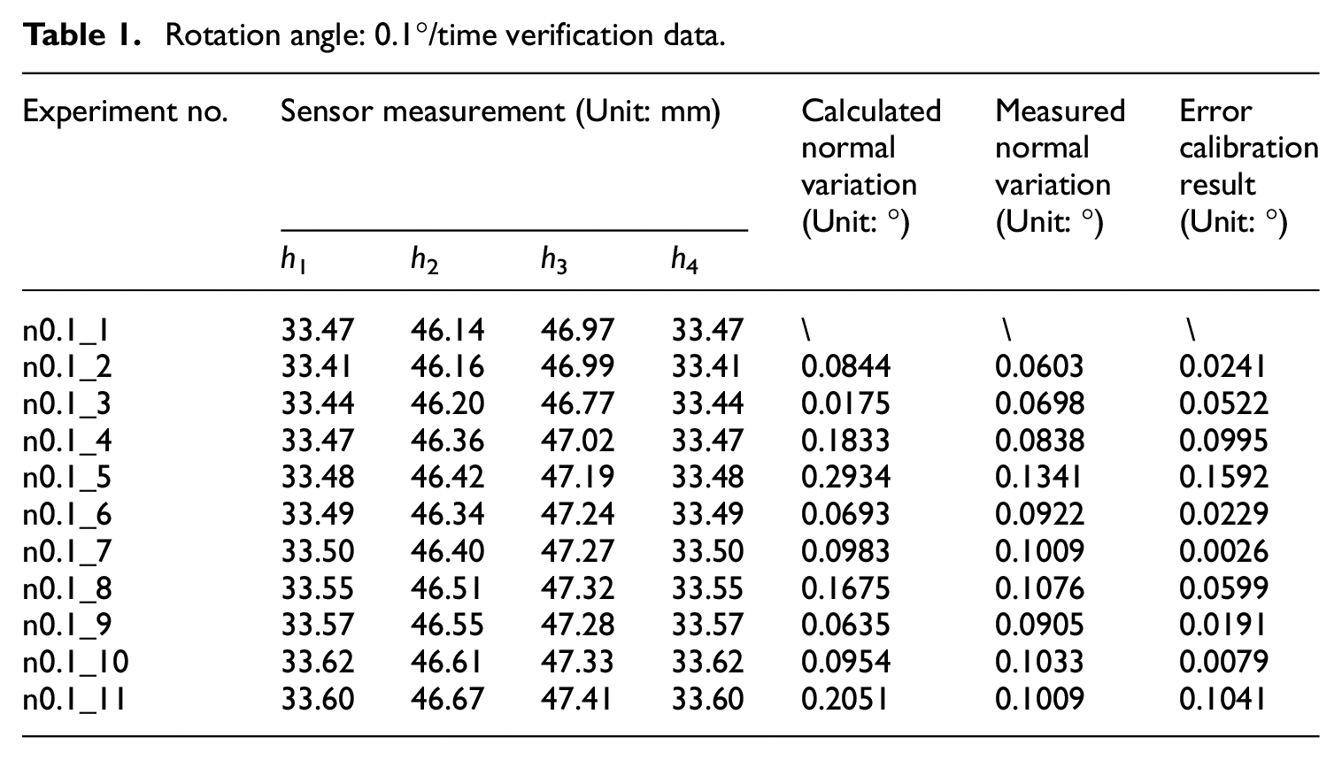
To determine the maximum effective angle range that this method can correct for the normal direction, the experimental results under different angle changes using the same method described above are compared, as shown in Figure 7. When the test is performed at different rotation angles on the angular motion table (such as in increments of 2°, 1°, 0.2°, 0.1°, etc.), the measured data of the test are as shown in Tables 1 and 2, and Figure 8.

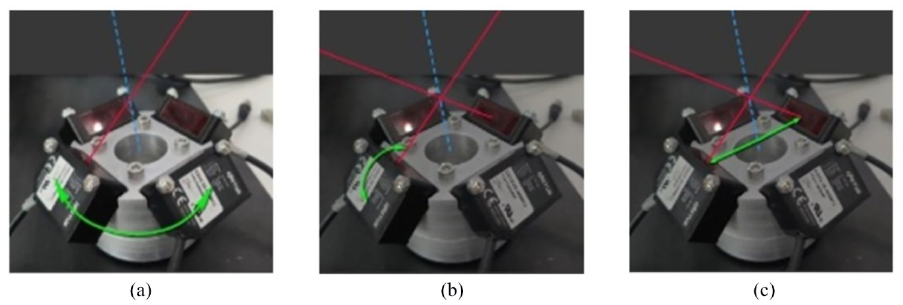
The normal-direction of alignment verification experiment scene. (a) Rotation angle: 0.1°/time. (b) Rotation angle: 1°/time.
Rotation angle: 0.1°/time verification data.
Rotation angle: 1°/time verification data.


Data analysis of the calculated normal deflection angle Angle_cal and the normal deflection angle Angle_act measured by theodolite. (a) The theodolite T1, T2 and the corresponding calibration blocks. (b) Scenes of experiments using a theodolite.
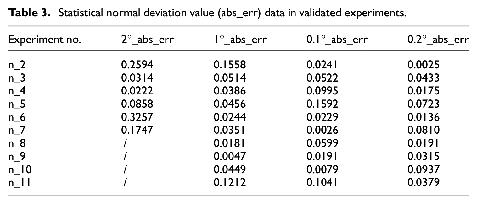
After the verification experiments, the values of the two normal angles Angle_cal and Angle_act are compared,, enabling us to statistically analyze the calibration accuracy abs_err. The specific data are shown in the Table 3 and Figure 9.
Statistical normal deviation value (abs_err) data in validated experiments.

In statistical experiments, compare the normal deviation data with 0.5°.
The above test results demonstrate the following properties of our method. The algorithm proposed in this paper is capable of normal-direction detection, calibration, and alignment based on the adaptive method. After the alignment, the deviation between the tool axis and the actual normal direction of the test surface is less than 0.5°, 24 and the average alignment error of the robot normal posture is 0.0667°. This meets the technical requirements for the alignment accuracy of the normal direction of the connection holes of aircraft products. Further analysis of the above experimental results shows that the positioning error of the robot studied by the proposed normal-direction correction method is affected by the comprehensive influence of many factors. The compensation algorithm in this study can only compensate for the positioning error caused by the geometric parameters of the robot, and can meet the working requirements of the existing project. If there are higher requirements for working environment conditions, such as temperature and other factors, it is necessary to further study the error compensation strategy, optimize the adaptive alignment method scheme and algorithm, and improve the reliability and adaptability of the robot calibration algorithm.
Conclusion
Automated assembly is the current development trend of aircraft assembly technology. Among various technologies, automatic drilling and riveting systems are widely used in aircraft manufacture due to the high-efficiency and high-quality assembly and connection. In this study, a normal-direction detection method based on adaptive calibration theory is proposed for an automatic drilling and riveting system to compensate the errors in detection. First, using a stable laser displacement sensor, the normal detection device was calibrated according to the method described in the research. Then, using an electronic theodolite to detect the actual normal-direction of the measured surface, and comparing it with the normal-direction measured by the sensor-based normal detection device, the accuracy of the detection system was verified. The comparison of multiple data points showed that after calibration, the deviation of the normal-direction obtained by the detection device was less than 0.5°, with an average value of 0.0667°. This meets the technical requirements for the vertical accuracy of holes in automatic drilling and riveting systems, and represents an improved detection accuracy.
Footnotes
Declaration of conflicting interests
The author(s) declared no potential conflicts of interest with respect to the research, authorship, and/or publication of this article.
Funding
The author(s) disclosed receipt of the following financial support for the research, authorship and/or publication of this article: This study was supported by National Key Research and Development Program of Major Scientific Instruments and Equipment’s Development, China, grant number (2017YFF0105304). This research was funded by Jilin Provincial Industrial Innovation Special Fund Project, China, grant number (2018C038-4). This research was funded by Jilin Province Science and Technology Development Plan Project, China, grant number (20200401117GX).