
Abstract
The variable stiffness joint is a kind of flexible actuator with variable stiffness characteristics suitable for physical human–robot interaction applications. In the existing variable stiffness joints, the antagonistic variable stiffness joint has the advantages of simple implementation of variable stiffness mechanism and easy modular design of the nonlinear elastic element. The variable stiffness characteristics of antagonistic variable stiffness joints are realized by the antagonistic actuation of two nonlinear springs. A novel design scheme of the equivalent nonlinear torsion spring with compact structure, large angular displacement range, and desired stiffness characteristics is presented in this article. The design calculation for the equivalent quadratic torsion spring is given as an example, and the actuation characteristics of the antagonistic variable stiffness joint based on the equivalent quadratic torsion spring are illustrated. Based on the design idea of constructing the antagonistic variable stiffness joint with compact structure and high compliance, as well as the different design requirements of the joints at different positions of the multi–degrees of freedom robot arm, nine types of mechanical schemes of antagonistic variable stiffness joint with the open design concept are proposed in this article. Finally, the conceptual joint configuration schemes of the robot arm based on the antagonistic variable stiffness joint show the application scheme of the designed antagonistic variable stiffness joint in the multi–degrees of freedom robot.
Keywords
Introduction
The variable stiffness joint (VSJ) is a kind of flexible actuator with adjustable joint output stiffness, which has the characteristics of independent and controllable link position and joint stiffness.1,2 At present, the VSJs and the multi–degrees of freedom (DOF) robot based on VSJ are mainly used in the rehabilitation training devices, the limb assist devices, and the artificial limbs.3–5 Taking the VSJ as the actuating joint of the rehabilitation training robot or the limb assist device, its inherent flexibility is conducive to ensuring the safety of the users, and its variable stiffness characteristics are conducive to improving the task adaptability of the devices. The VSJ and the multi-DOF robot system based on the VSJ have important research and application value in the field of physical human–robot interaction.
Although there are many types of VSJs at present, two types of VSJs have been focused on: one is based on the equivalent lever mechanism with series actuation structure, the other is the antagonistic VSJ based on nonlinear spring with parallel actuation structure. Compared with the VSJ based on the equivalent lever mechanism with series actuation structure, the energy consumption of stiffness adjustment of the antagonistic VSJ is higher, but it also has many advantages, such as relatively simple implementation of the variable stiffness mechanism and modular design of the nonlinear elastic element. Therefore, the antagonistic VSJs also have more research and good application prospects.
The mechanical design of the equivalent nonlinear spring and the antagonistic VSJ has an important influence on the actuation characteristics and application of the antagonistic VSJ. Mechanical design is the first consideration in the research of the antagonistic VSJs. In order to implement a single-DOF antagonistic VSJ, Migliore et al. 6 constructed two types of nonlinear springs with quadratic force–displacement relationship, one is based on the tension spring and the frame with expected contour, the other is based on the linear tension spring and the cam with expected contour. Based on the bionic design idea, Masahiko et al. 7 designed an antagonistic VSJ for humanoid skeletal muscle driven robot, and the nonlinear elastic element based on the rotatable base and the linear compression spring makes the antagonistic VSJ have variable stiffness characteristics. In order to have a good trade-off between mechanical complexity and overall performance, Catalano et al. 8 used enumeration and analysis methods to select the mechanical design layout of the antagonistic VSJ, and a nonlinear elastic element based on the four-bar linkage and the linear torsion spring is designed for the antagonistic VSJ. A nonlinear elastic element based on the leaf spring and the four-bar mechanism is designed by Wang and Huang, 9 and an antagonistic VSJ driven by worm gear mechanism is implemented. Inspired by the antagonistic driving mechanism of the skeletal muscle, an antagonistic VSJ based on the nonlinear spring with exponential force–displacement relationship is implemented, and the designed geometric profile of the cam with V-groove makes the equivalent nonlinear spring have the desired stiffness characteristics. 10 In order to implement an antagonistic VSJ with compact structure, Palli et al. 11 designed a plane torsional spring as the compliant transmission element of the antagonistic VSJ, and the relationship between angular displacement and torque of the compliant element is quadratic. Kilic et al. 12 present a design method of the nonlinear torsional spring with the desired stiffness characteristics, and the equivalent nonlinear spring used in the antagonistic VSJ mainly includes transmission line, tension spring, and the cam with desired contour. Schmit and Okada 13 provide another design method of the nonlinear torsional spring with desired stiffness characteristics, which is realized by designing the profile of the non-circular cable spool. An antagonistic VSJ with unlimited rotation angle of output shaft is designed by Malosio et al., 14 and the nonlinear spring is characterized by a customizable stiffness characteristic made up of a tension spring, a cam, and a wire. An equivalent nonlinear spring based on harmonic gear mechanism, linear compression spring, roller bearing, and cam disk mechanism with special profile is designed by Petit et al., 15 and it is used in the bidirectional antagonistic VSJ. Spagnuolo et al. 16 designed an equivalent nonlinear spring based on the transmission line, the linear tension spring, and the planar cam mechanism with desired contour, and it is used in an antagonistic VSJ suitable to perform linear motion.
Although there are many studies on the equivalent nonlinear spring and the antagonistic VSJ, there are still many problems in the mechanical design of the antagonistic VSJ. The volume of the equivalent quadratic spring and the antagonistic VSJ designed by Migliore et al. 6 is large. The output shaft of the antagonistic VSJ designed by Masahiko et al. 7 can only provide swing motion, and the joint stiffness characteristics cannot have the desired stiffness characteristics due to the influence of the stiffness characteristics of the equivalent nonlinear spring. Although the structure of the antagonistic VSJ designed by Catalano et al. 8 is compact, the joint stiffness is difficult to have the desired stiffness characteristics due to the motion characteristics of the transmission mechanism of the equivalent nonlinear torsional spring. Although the antagonistic VSJ designed by Wang and Huang 9 and the antagonistic VSJ based on flexures designed by Palli et al. 11 have the advantages of compact structures, the joint angle deviation range is small and the degree of compliance of the joint is low due to the structural characteristics of the nonlinear elastic elements. Although the equivalent nonlinear spring designed by Sen 10 has the expected stiffness characteristics, the volume of the equivalent nonlinear spring is large, which leads to the large volume of the joint and the limited rotation range of the joint output shaft. The existing design methods of the equivalent nonlinear spring with desired stiffness usually adopt transmission line, linear tension spring, and cam mechanism with desired contour.12–14,16 However, the calculation of these methods is complex, and the volume of these equivalent nonlinear springs is large, which is not suitable for the construction of antagonistic VSJs with compact structure. Compared with the antagonistic VSJs mentioned above, the parallel-type VSJ based on antagonistic actuation designed by Nam et al. 17 has the advantages of compact structure and unlimited rotation angle range of output shaft, but it does not have the desired stiffness characteristics.
Although there are many studies on the mechanical design of the antagonistic VSJ, the existing antagonistic VSJ has many disadvantages in the mechanical design, such as large volume and the joint stiffness is difficult to have the desired stiffness characteristics. This will limit the application of this type of VSJ in the field of service robots and rehabilitation training robots. Therefore, it is necessary to further study the mechanical design of the antagonistic VSJ. The mechanical design of antagonistic VSJ and the multi-DOF robot arm based on the antagonistic VSJ is still an open research field.
The main innovations and contributions of this article are presented as follows:
Based on the cam-roller mechanism and the linear compression spring, a novel mechanical structure scheme of the equivalent nonlinear torsion spring with compact structure, large angular displacement range, and desired stiffness characteristics is proposed. Compared with the existing equivalent nonlinear torsion spring design scheme,6–16 the design scheme in this article has the advantages of compact structure, wide range of angular displacement, simple calculation method, and easy to obtain the desired stiffness characteristics.
Taking the mechanical design of the equivalent quadratic torsion spring (EQTS) as an example, in order to design the equivalent nonlinear torsional spring with compact structure and large angular displacement range, as well as the different structural requirements and actuation requirements of the joints at different positions of the robot arm, and in line with the open design idea, eight types of EQTSs with different structural schemes are designed. The equivalent nonlinear torsional spring with the large angular displacement range can make the antagonistic VSJ have high compliance, so as to improve its variable stiffness range and physical human–robot interaction security.
Based on the designed EQTS, the conceptual model of the antagonistic VSJs of nine structural schemes are designed. The friction damper (FD) based on the linear compression spring and the ball screw mechanism is used to reduce the vibration of the output shaft of the antagonistic VSJ caused by the elastic element. The damping torque provided by the FD is proportional to the amount of deformation of the linear compression spring. Finally, the conceptual models of the robot arm driven by the antagonistic VSJ show the joint configuration application schemes of the designed antagonistic VSJ in the multi-DOF robot arm.
This article is organized as follows. The “Principles and layouts of the antagonistic VSJ, the EQTS, and the FD” section describes the conceptual layouts of the antagonistic VSJ and the EQTS. The principles of the EQTS and the FD are illustrated. The section “Mechanical solutions of the antagonistic VSJs with the FDs” presents the actuating characteristics of the EQTSs and the antagonistic VSJ equipped with FDs, and the mechanical solutions of the antagonistic VSJs and the FDs are demonstrated. The section “Conceptual modeling of the 6-DOF robot arm based on the antagonistic VSJ” shows the conceptual models of four types of 6-DOF antagonistic variable stiffness robot arms. Finally, conclusions and future works are discussed in the section “Conclusion and future work.”
Principles and layouts of the antagonistic VSJ,the EQTS, and the FD
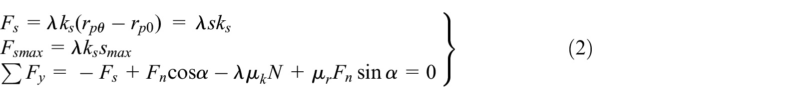
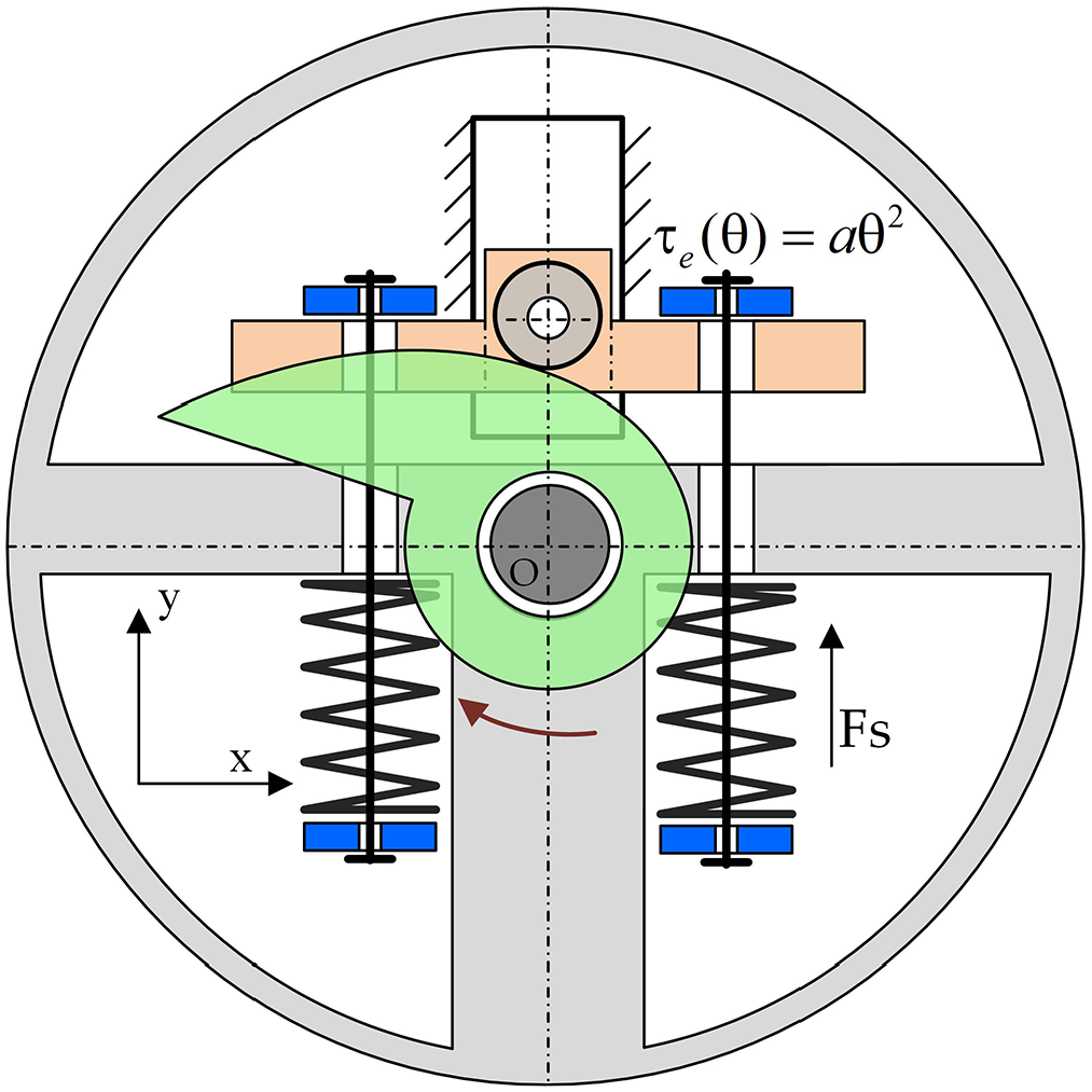
In this article, taking the antagonistic VSJ based on the EQTS as an example, the design idea of the equivalent nonlinear torsion spring and the working principle of the antagonistic VSJ are shown. The elastic torque–angular displacement characteristic of the EQTS is defined as τe(θ) = aθ2, where θ is the angular displacement of the EQTS. When the VSJ is actuated by two identical quadratic springs in the form of antagonism, the elastic actuation torque M(β) and joint stiffness Kej of the antagonistic VSJ are given by equation (1). The β is the joint angle deviation,

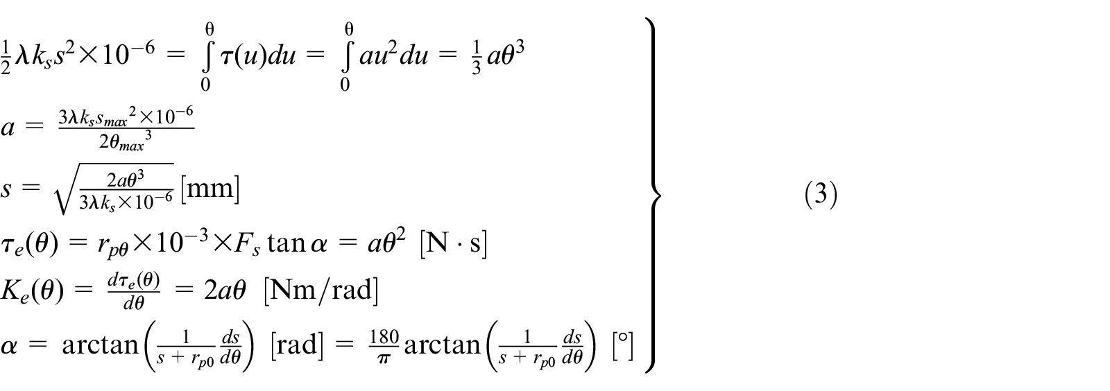
In this section, taking the design and calculation of the EQTS as an example, the mechanical design scheme of the equivalent nonlinear torsional spring is presented. The EQTS is realized by designing the contour of the plane groove cam. As shown in Figure 1, under the action of the external torque, the cam produces an angular displacement θ. The roller bearing is installed on the spring bracket through a shaft. Because of the reaction force of the spring, the roller bearing keeps contact with the cam contour all the time. When the cam produces an angular displacement θ, the spring bracket produces a displacement s along the y-axis direction. The deformation of the linear compression spring is s, and the equivalent quadratic spring produces an elastic actuation torque τe(θ) = aθ2. The corresponding calculations are shown in equations (2) and (3), and this calculation is based on the law of conservation of energy. The designed equivalent nonlinear torsional spring has a wide range of angular displacement, and its layout scheme is suitable for the implementation of the antagonistic VSJs with compact structure
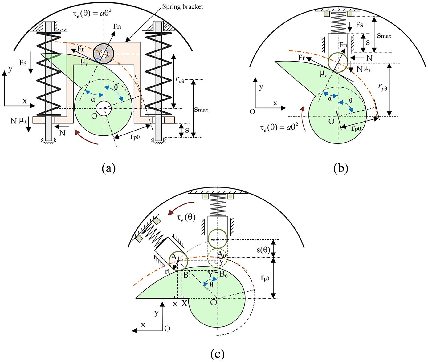
Conceptual layout of the EQTS: (a) The conceptual layout of the EQTS, (b) the schematic of the EQTS, and (c) the calculation scheme of the cam profile.
The calculation of the cam profile of the equivalent quadratic spring is shown in equation (4). In Figure 1(c), assuming that the cam remains fixed and the roller follower rotates at an angle along counterclockwise, the contact point between the roller bearing and the cam profile moves from point B0 to point B1. The coordinates of the point A1 are expressed as (x, y), and the coordinates of the point B1 are expressed as (X, Y)

The symbolic definitions of equations (2)–(4) are shown in Table 1. Because there is good sliding contact between roller bearing and cam profile, and the rotational angular velocity of equivalent quadratic spring is low, the energy loss caused by friction is not considered for the sake of simplified calculation.
Symbolic definitions for calculating EQTS.
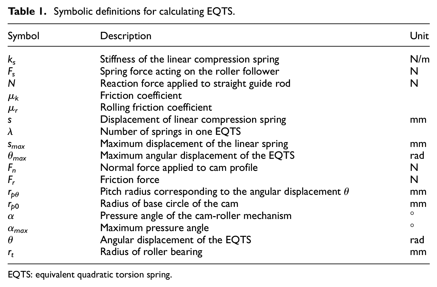
EQTS: equivalent quadratic torsion spring.
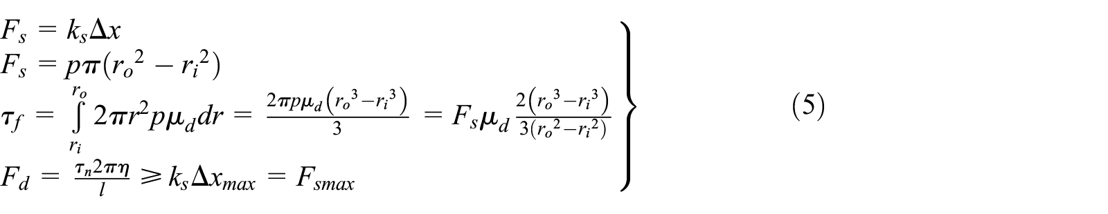
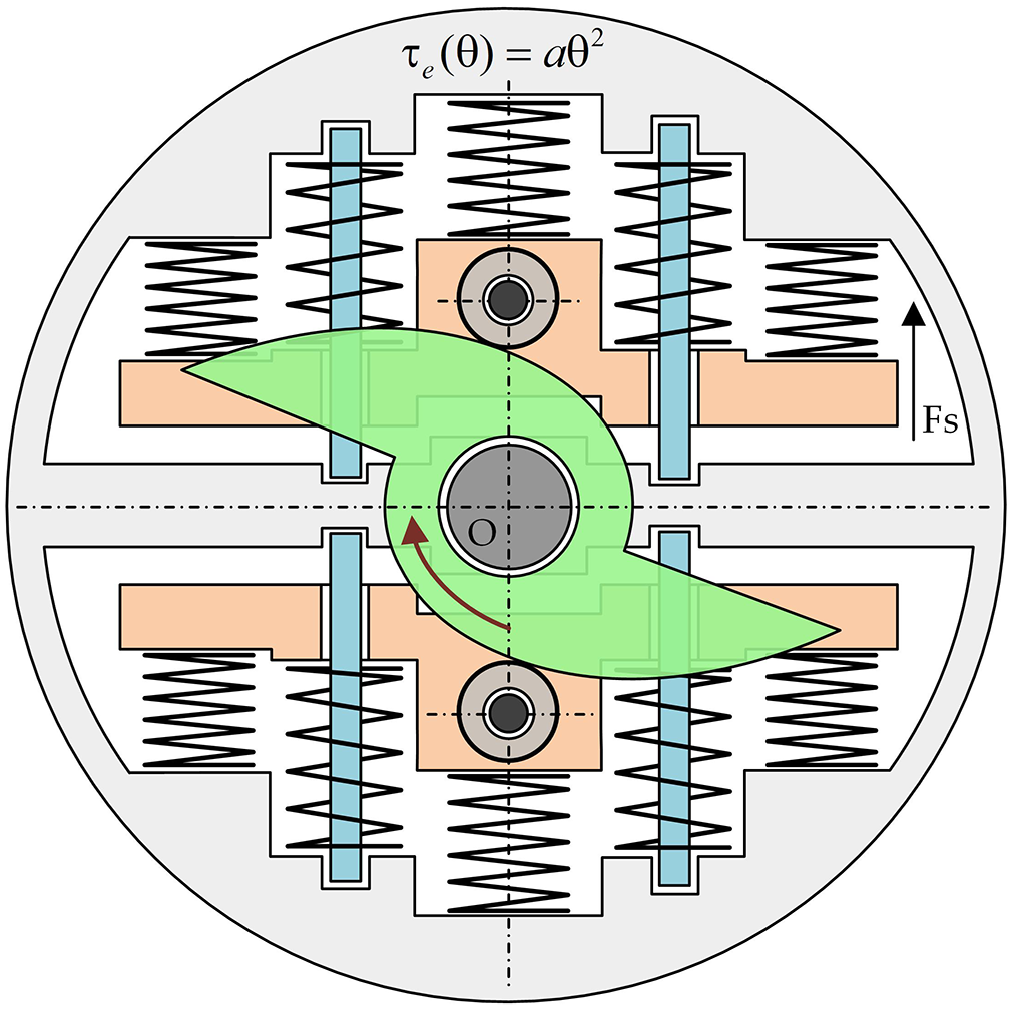
In this article, the FD18,19 is designed to suppress the vibration of the output shaft of the antagonistic VSJ. As shown in Figure 2, the static friction disk is driven axially by a damping control motor through a ball screw mechanism. When the screw nut moves along the axial direction, the linear compression spring is compressed. The spring force is applied to the static friction disk, which contacts with the dynamic friction disk and generates the friction torque applied to the output shaft of the antagonistic VSJ. The friction torque can be adjusted by changing the magnitude of the spring force, that is, by adjusting the angular displacement of the damping motor to achieve the friction torque control. In the selection of the damping motor, the normal force Fd should be larger than the maximum spring force. In order to calculate the capacity of the FD to generate damping torque, the uniform pressure theory is used. Assume that the friction surface is an annular sector A, formed by the two pads. For this type of friction surface geometry, the friction torque τf is described by equation (5). The P represents a uniform pressure applied to the area A. The dynamic friction coefficient μd is considered to be constant. The parameters of equation (5) are described in Table 2
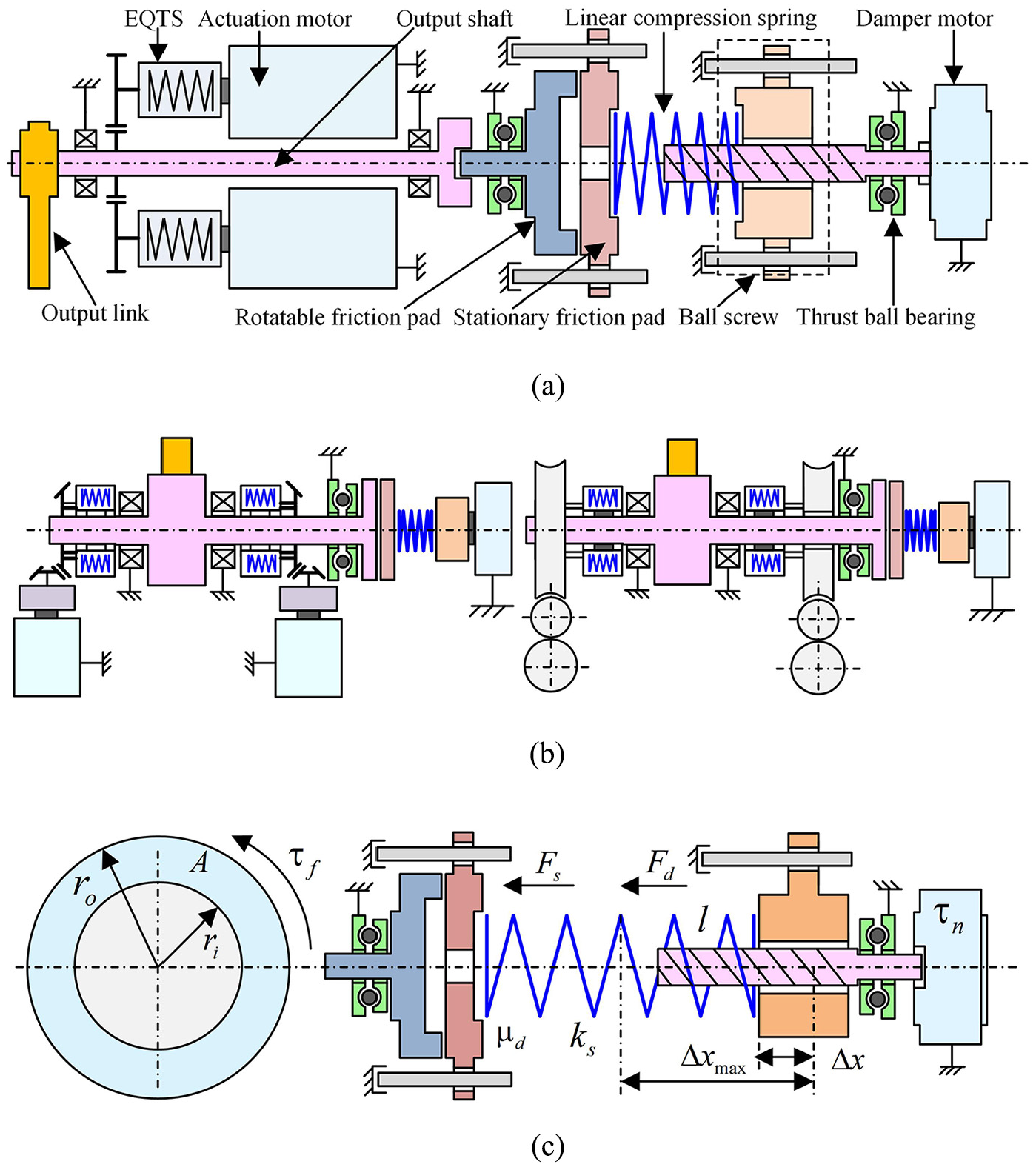
Mechanism schematic of the antagonistic VSJ equipped with the friction damping mechanisms: (a) The conceptual layout of the rotary VSJ having a FD, (b) the conceptual layout of the swing VSJ having a FD, and (c) the calculation schematic of the friction damper.
Symbols used for schematic description of the FD.

FD: friction damper.
Mechanical solutions of the antagonistic VSJs with the FDs
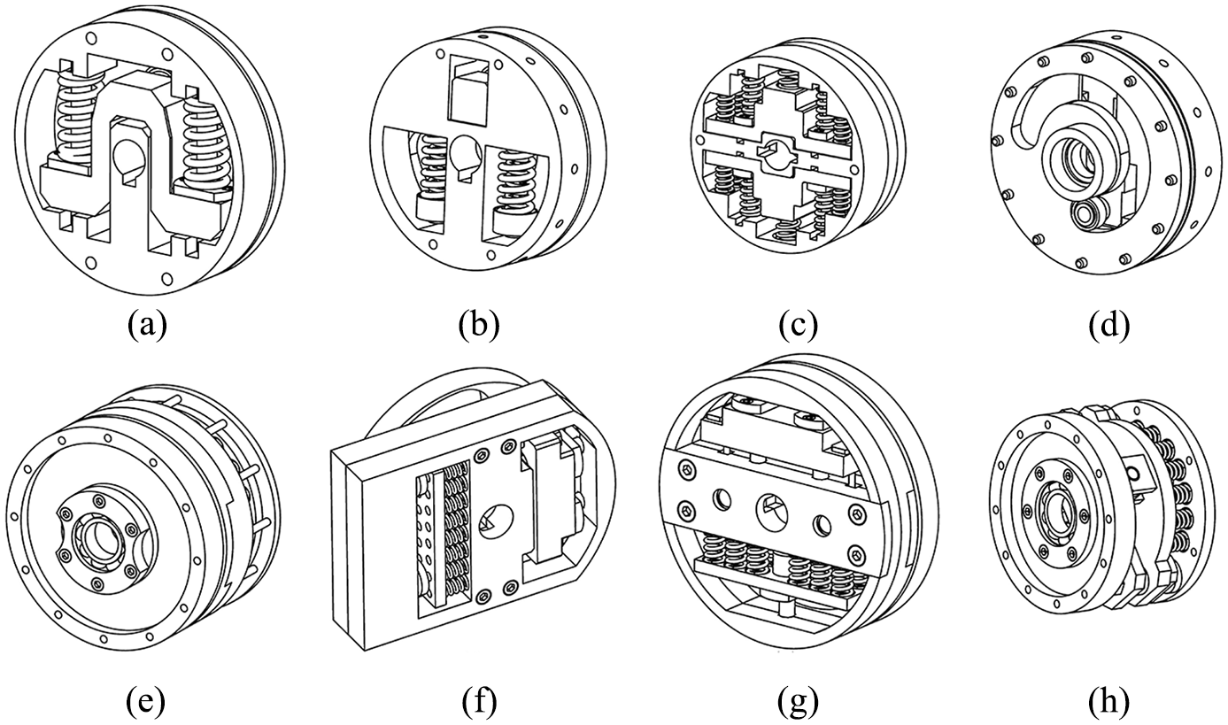
The conceptual layouts of the eight types of EQTSs are shown in Figure 3. The EQTS-h shown in Figure 3(h) is the unfolded profiles of the cylindrical cam mechanism with straight moving roller follower. The seven other EQTSs (e.g. the EQTS-a to the EQTS-g) are mainly composed of the planar groove cam mechanism with roller follower and the compression spring. The cam and the springs are in the different working planes. The planar groove cam drives the roller bearing mounted on the spring bracket, and the linear compression springs are compressed. For the EQTS-a, the roller pedestal is guided by the linear bearings and the linear guides. The friction losses are small. Compared with the EQTS-a, the tendons are used in the EQTS-b, and the size and the weight of the EQTS-b are reduced. A compact design can be achieved. In order to further reduce the volume of the EQTS and to ensure the large elastic load capacity, the EQTS-c is proposed. As shown in Figure 3(d), in order to further increase the collision safety, the cam profile of the EQTS-d is divided into two segments. The pressure angle is an important evaluation parameter in the cam-roller mechanism, and reducing the pressure angle is beneficial for smoothness of motion. In order to reduce the pressure angle and achieve a compact design, the EQTS-e, the EQTS-f, and the EQTS-g are designed.

Conceptual layout of the EQTSs used in the antagonistic VSJ: (a) EQTS-a, (b) EQTS-b, (c) EQTS-c, (d) EQTS-d, (e) EQTS-e, (f) EQTS-f, (g) EQTS-g, and (h) EQTS-h.
Mechanical structure design of the first type of antagonisticVSJ based on the EQTSs
The conceptual layout of the EQTS used in the first type of antagonistic VSJ is shown in Figure 3(a). The designed EQTS can only provide unidirectional torque, but its angular displacement range is large. The antagonistic VSJ equipped with this EQTS can have a large range of joint angle deviation and high compliance.
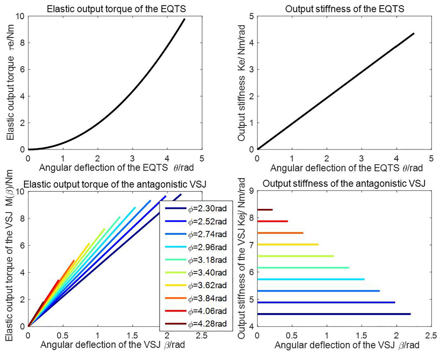
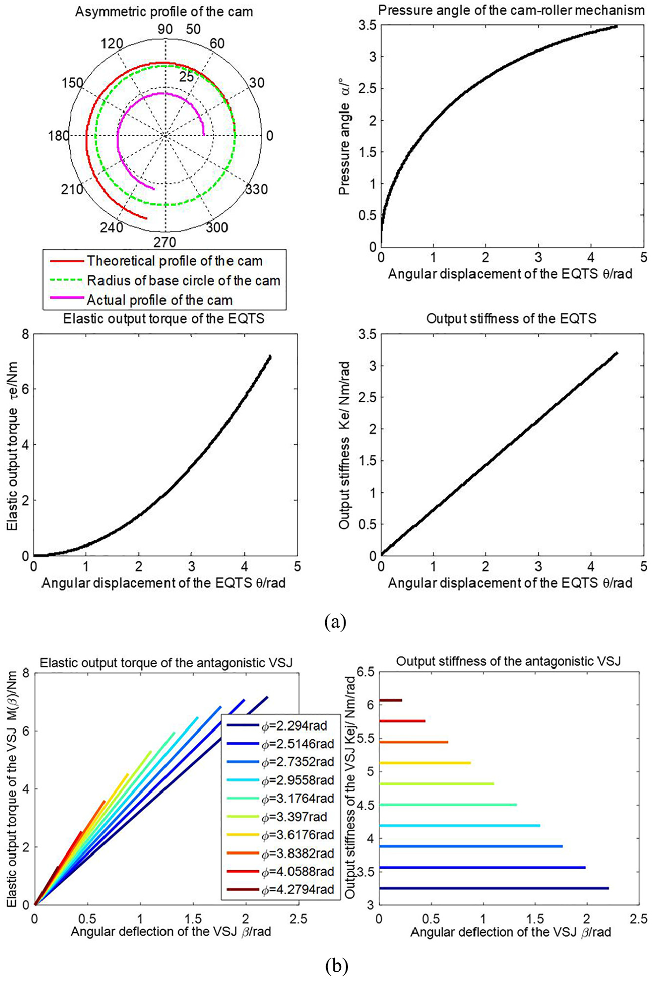
The cam profile curve of EQTS, the pressure angle curve of cam-roller mechanism, the elastic actuation torque and stiffness curve of EQTS, the elastic actuation torque, and joint stiffness curve of antagonistic VSJ (corresponding to equation (1)) are shown in Figure 4. The cam profile curve is asymmetric and can provide a large range of angular displacement. The pressure angle of the cam-roller mechanism is very small, which is beneficial to improve the movement stability of the EQTS. The angular displacement–stiffness curve of the EQTS is linear. The joint stiffness of the antagonistic VSJ is only related to the initial preload of the EQTS.

The actuation characteristics of the EQTS and the first type of antagonistic drive joint (ADJ): (a) The characteristics of the first type of EQTS and (b) the elastic actuating torque and output stiffness of the first type of antagonistic VSJ.
The cylindrical helical spring with circular cross-section are used in the EQTSs. The spring parameters are defined as follows: pn is the maximum working load of the spring, D is the mean coil diameter of the spring, pj is the allowable working ultimate load of the spring, d is the diameter of the spring wire, H0 is the free length of the spring, b is the ratio of the H0 and the D, n is the number of active coil of the spring, n1 is the total coil number of the spring, and ks is the spring stiffness coefficient. The maximum working loads of the springs should be less than the limit loads (e.g. pn < pj). The parameters of the spring are defined as follows: H0 = 60 mm, d = 5 mm, D = 25 mm, ks = 65.83 N/mm, n = 6, n1 = 8, b = 2.4, λ = 2, and smax = 15 mm. The parameters of the cam-roller mechanism are defined as rt = 14 mm, rp0 = 37.5 mm, αmax = 5.44°, and θmax = 4.5 rad. The maximum allowable angular deflection of the antagonistic drive joint (ADJ) is defined as βmax = ±2.2 rad, and the initial angular displacement of the EQTS is ϕ = 2.3 rad. The elastic torque of the ADJ is from 0 to 9.87 N m. The joint stiffness range at the elastic transmission of the ADJ is from 4.49 to 8.78 N m/rad.
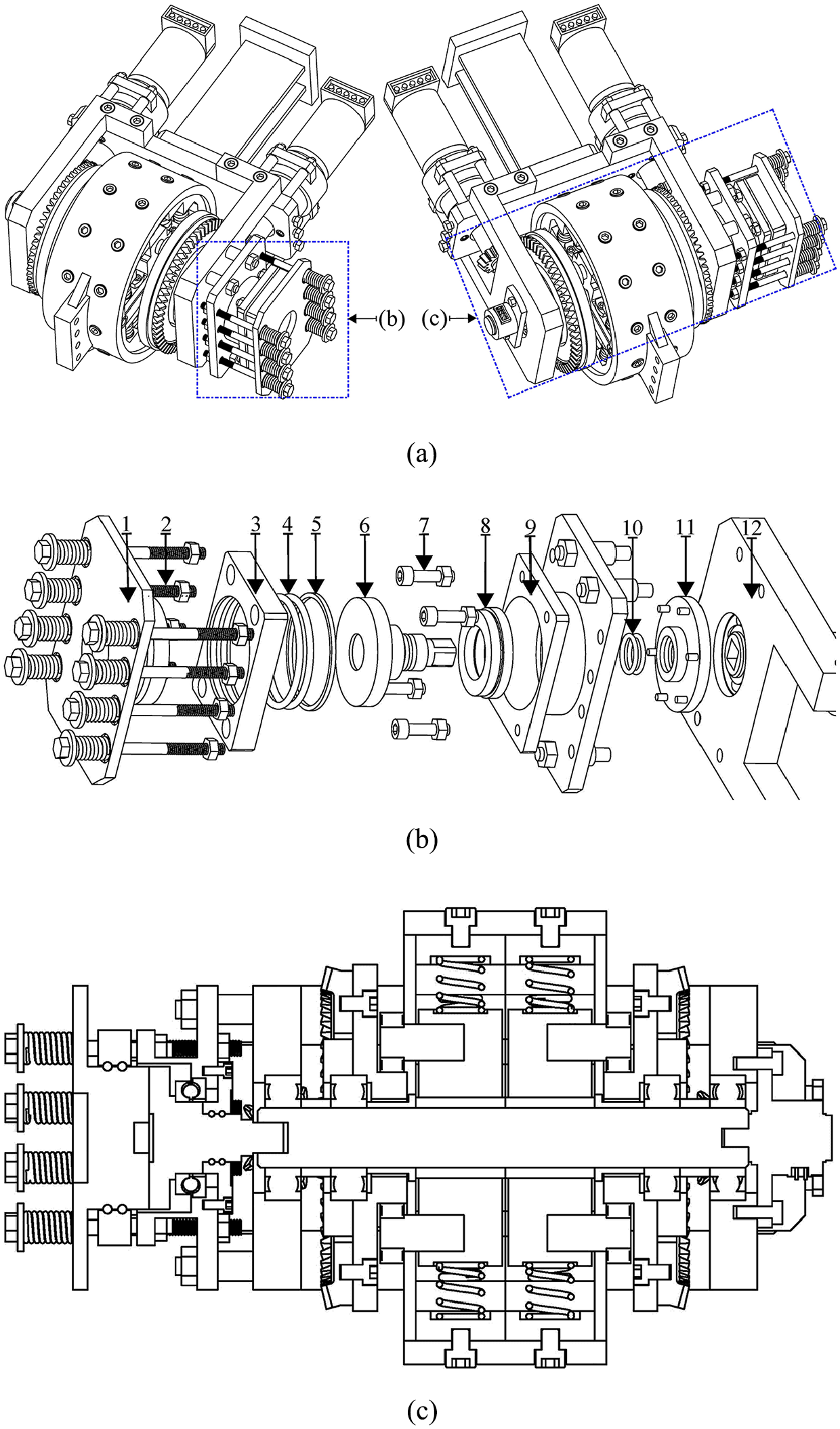
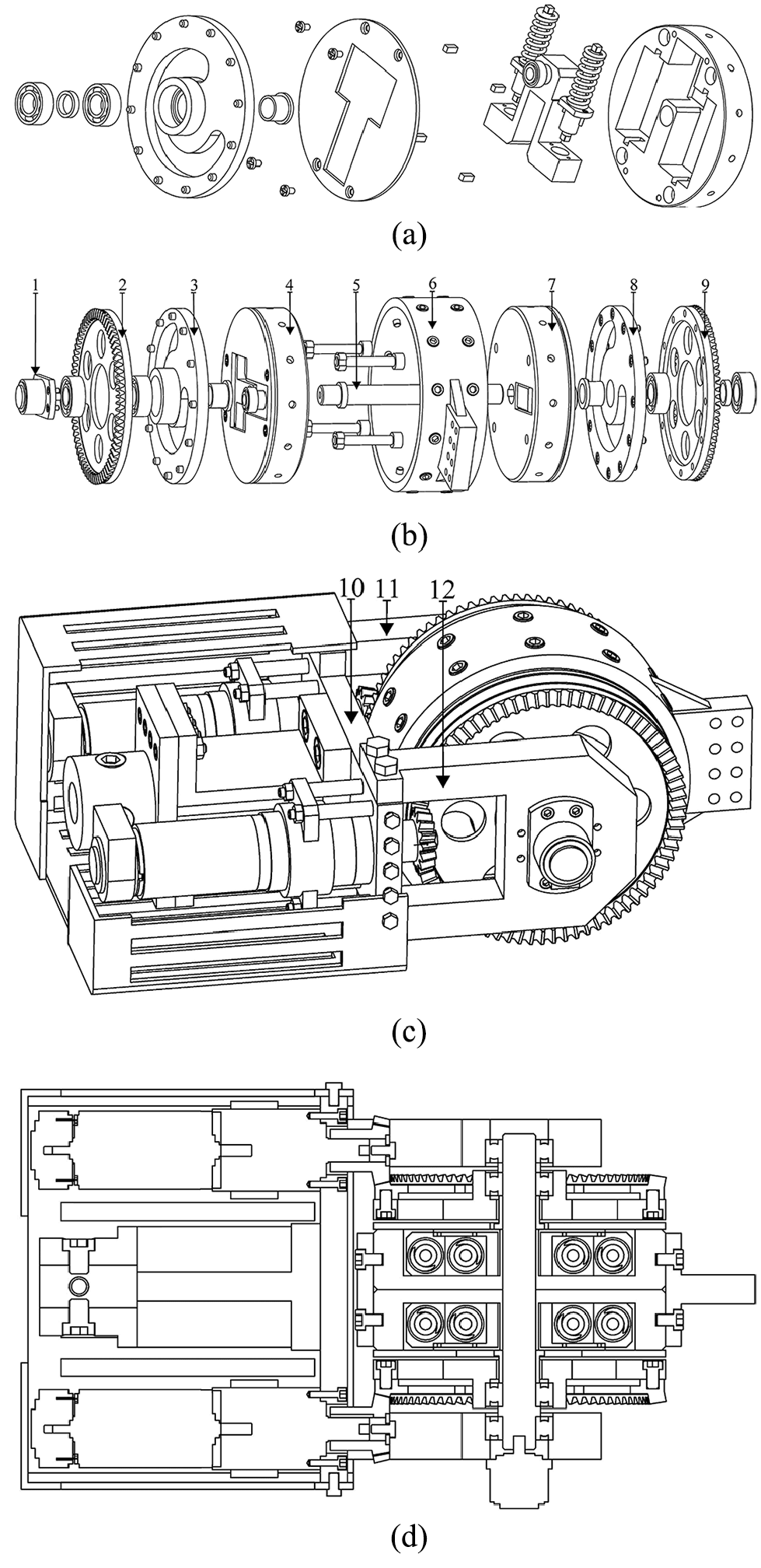
The mechanical structure solutions of the first type of antagonistic VSJ are shown in Figure 5. The bearing (2) is installed in the grooved cam (3). The bearing cover (1) is connected with the (3). The shaft bushing (4) is used for axial positioning of the cam components. One end of the (4) contacts with the (2), and the other end of the (4) contacts with the cylindrical body (5). The roller bearing (6) and the pin shaft (7) are installed at the roller pedestal (9). The linear guide rod (8) and the linear bearing (11) is used to reduce the friction resistance.

The mechanical solutions of the antagonistic EQTS and the first type of antagonistic VSJ: (a) Exploded view of the lower EQTS, (b) exploded view of the upper EQTS, (c) exploded view of the antagonistic actuation module, (d) exploded view of the whole antagonistic output assembly, and (e) exploded view of the FD of the first type of antagonistic VSJ (damper motor is omitted).
The antagonistic actuation module of the first type of antagonistic VSJ is shown in Figure 5(c). The two EQTSs are fixedly connected together by the screw bolts (15). The block (18) is used to position the linear guide rod. The rectangular faced key (17) is mounted on the output shaft (16). The axial positioning of the (16) in the assembly is achieved by the (17). The bushing (19) and the bearing (20) are used for the axial positioning of the upper EQTS. The bushing (14) and the bearing (13) are used for the axial positioning of the lower EQTS. The supporting plate (12) is functioning as a base. Figure 5(d) shows the internal structure of the antagonistic output assembly. The two reducers (e.g. the (21) and the (22)) are mounted on the (12). The stationary housing (28) is fixedly connected with the (12). The spur gear (24) is driven by the (21). The internal ring gear (23) is fixedly connected with the hollow cylindrical body (27). The (27) is connected with the grooved cam (10). By engaging the (23) and the (24), the motion of the upper EQTS can be realized. The second pinion gear (26) is meshed with the second ring gear (25). The (25) is fixedly connected with the (3). The rotational motion of the lower EQTS is realized by engaging the (25) and the (26). Figure 5(e) shows the mechanical solutions of the fraction damping mechanism. The supporting plate (29) is fixedly connected with the (12). The thrust bearing (30) is used to take the axial load off the damper motor. When the lead screw (31) is rotated by the damper motor, the screw nut is moved along the axial direction of the linear guide rod (32). The thrust bearing (41) is installed into the supporting pedestal (42). A sealed space is consisted by the stationary friction disk (36), the large O-ring (37), the hollow body (38), the circular sealing gasket (39), the supporting pedestal (42), the small O-ring (43), and the bearing cover (44). When the stationary friction disk (36) is in contact with the rotatable friction disk (40), the damping torque is generated. The amount of pre-deformation of the small spring (35) can be altered by tuning the four adjustable bolts and so the initial pressure applying on the rotatable friction pad can be reconfigured. The parameters of the friction interface and the range of the torque for the cases of a lubricated contact are listed in Table 3.
Parameters of the fraction damping mechanism.

The parameters of the damping mechanism are presented as follows. The ball screw pitch l = 2 mm. The diameter of the lead screw is Φs = 12 mm. The stall torque of the damper motor is τD = 1.48 N m, and the nominal torque is τn = 0.067 N m. The ratio of the planetary gearbox is 16:1. The parameters of the springs are listed in Table 4. The initial pressure and the maximum pressure applied on the interface are Fdsi = 26.35 N and Fdsmax = 1527.66 N, respectively. The axial thrust force provided by the ball screw mechanism is Fdsn = 2694.23 N (Figure 6).
Parameters of the springs used in the FD of the first antagonistic VSJ.
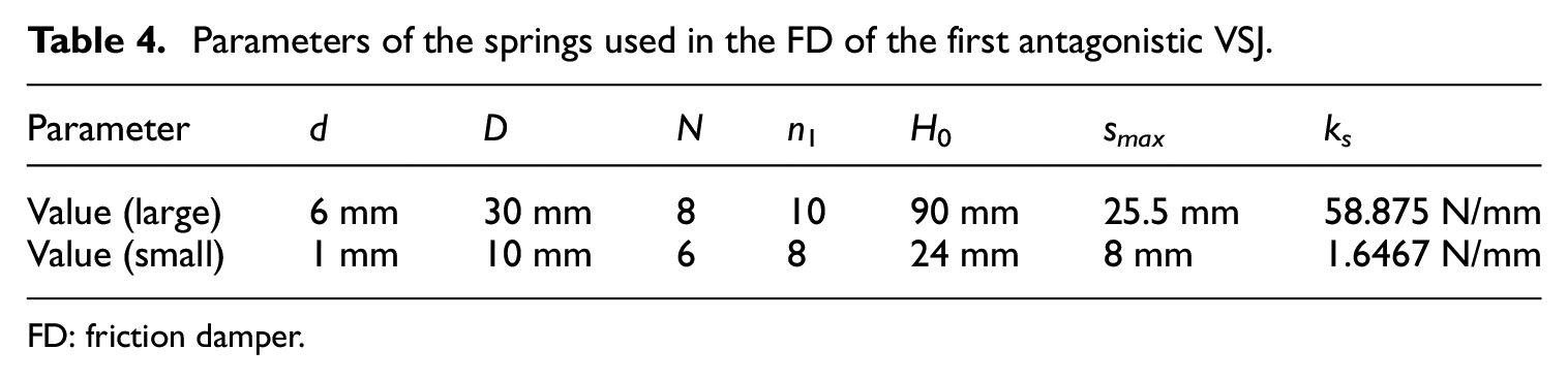
FD: friction damper.
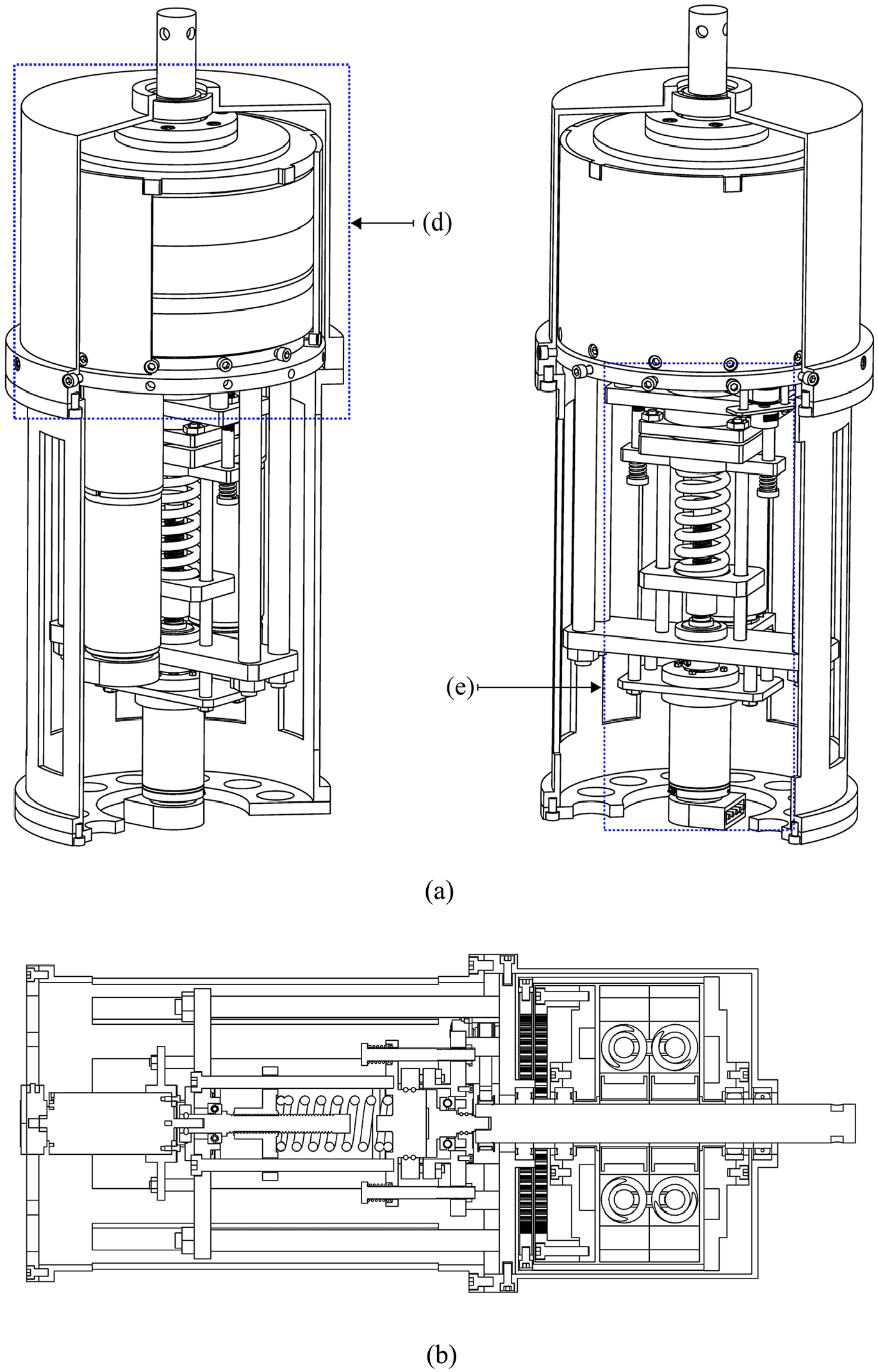
Mechanical solution of the first antagonistic VSJ: (a) 3D view of the first type of antagonistic VSJ and (b) sectional view of the first type of antagonistic VSJ.
Mechanical structure design of the second type of antagonisticVSJ based on the EQTSs
In the design of the first type of EQTS, the linear bearings and the guide rods are used to guide the roller pedestal. The maximum force acting on the roller pedestal is denoted by Fsmax. As shown in equation (6), under the same θmax, the roller pedestal will withstand more pressure if the τe(θmax) is increased. Therefore, for the roller pedestal, the structural strength and dimension should be reasonably selected and designed. In order to reduce the weight of the EQTS, the tendons are used to compress the spring in the second type of EQTS, and the roller pedestal is moved along the guide slot of the EQTS. In addition, in order to increase the load capacity, the combined spring set is used. For the second type of EQTS, the parameters of the cam-roller mechanism (e.g. rp0, rt, smax, θmax) is same as the first type of EQTS (Figure 7). The profile curve of the cam and pressure angle of the cam-roller mechanism are not affected by the stiffness of the spring, as shown in equation (7)


Conceptual layout of the second type of EQTS.
In the second type of EQTS, the parameters of the spring with a large diameter are defined as follows: H0 = 55 mm, d = 4 mm, D = 20 mm, ks1 = 45.143 N/mm, n = 7, n1 = 9, b = 2.75, and λ1 = 2. The parameters of the spring with a small diameter are defined as follows: H0 = 50 mm, d = 2.5 mm, D = 12 mm, ks2 = 20.273 N/mm, n = 11, n1 = 13, λ2 = 2, and b = 4.17. The radial clearance between the two springs is 0.75 mm. The equivalent stiffness of the spring set is 65.416 N/mm. The maximum elastic torque and output stiffness of the second type of EQTS are τe(θ) max = 9.8124 N m and Ke(θ) max = 4.361 N m/rad, respectively. The maximum angular deflection βmax of the second type of antagonistic VSJ is ±2.2 rad, and the initial angular displacement of the EQTS is ϕ = 2.3 rad. The actuating characteristics of the second type of EQTS and the antagonistic VSJ are shown in Figure 8.
The actuation characteristics of the EQTS and the second type of antagonistic VSJ based on EQTS.
As shown in Figure 9, the bearing cap (1), the bearing (2), and the shaft bushing (4) are used for the axial positioning of the grooved cam (3). In order to reduce the weight of the EQTS and increase the elastic load capacity, the combined spring set (e.g. the large spring (7) and the small spring (8)) and the tendon (9) are used. For the combined spring set, the two springs are placed coaxially inside the spring pedestal (6). The direction of rotation of the two adjacent compression springs should be opposite.

Mechanical solution of the second antagonistic VSJ: (a) Exploded view of the second type of EQTS, (b) exploded view of the antagonistic actuation module, (c) exploded view of the friction damping mechanism used in the second type of ADJ (damper motor is omitted), (d) 2D sectional view of the second type of antagonistic VSJ, and (e) CAD assembly of the second type of antagonistic VSJ.
In Figure 9(c), the supporting plate (20) is functioning as a frame. The supporting pedestal (19) is mounted on the (20). The thrust ball bearing (18) is used to withstand the axial load from the rotatable friction pad (17). Another thrust ball bearing (11) is used to withstand the axial load from the spring set. The spring action plate (14) is driven by the ball screw mechanism (e.g. the nut (13) and the lead screw (12)). The spring (15) is used for applying the preload force to the stationary friction pad (16). The parameters of the compression springs used in the FD are listed in Table 5. Assume that the amount of deformation of the small spring is s = 5 mm. The initial force and the maximum force applied on the friction interface are Fdsi = 22.2 N and Fdsmax = 884.84 N, respectively.
Parameters of the springs used in the FD of the second antagonistic VSJ.

FD: friction damper.
The parameters for the friction interface and the range of the damping torque are listed in Table 6. The ball screw pitch l = 2 mm. The diameter of the lead screw is Φs = 12 mm. The stall torque of the damper motor is τD = 4.18 N m, and the nominal torque is τn = 0.227 N m.
Parameters of the friction damping mechanism of the second antagonistic VSJ.

Mechanical structure design of the third and fourth typeof antagonistic VSJ based on the EQTSs
In order to further reduce the volume of the EQTS and to ensure a high elastic load capacity, the cam having two identical profiles is proposed. As shown in equation (8), the τe(θmax) and the Ke(θmax) of the EQTS will increase with the reduction of the θmax. The spring set are used to increase the energy density of the EQTS. This EQTS is selected as the elastic element of the third and fourth types of antagonistic VSJs. The conceptual structural scheme of the third type of EQTS is shown in Figure 10

Conceptual schematic of the third type of EQTS.
The parameters of the linear compression springs used in the third type of EQTS are listed in Table 7. The equivalent stiffness of the spring set is ke = 287.06 N/mm. The parameters of the cam-roller mechanism are defined as follows: rt = 10 mm, rp0 = 32 mm, αmax = 6.21°, and θmax = 2.618 rad. The elastic torque and stiffness of the EQTS are τe(θ) max = 9.252 N m and Ke(θ) max = 7.067 N m/rad, respectively. The maximum angular deflection βmax of the antagonistic VSJ is defined as ±1.26536 rad. The initial angular displacement of the EQTS is ϕ = 1.35263 rad. The elastic torque range of the VSJ is from 0 to 9.241 N m, and the joint stiffness range of the VSJ is from 7.303 to 14.1351 N m/rad. The actuating characteristics of the EQTS and the third type of antagonistic VSJ are shown in Figure 11.
Parameters of the springs used in the EQTS.

EQTS: equivalent quadratic torsion spring.

The actuation characteristics of the EQTS and the third type of antagonistic VSJ: (a) The actuation characteristics of the third type of EQTS and (b) the elastic actuating torque and output stiffness of the third type of antagonistic VSJ.
As shown in Figure 12(a), three types of springs (e.g. the (1), the (2) and the (3)) are used in the EQTS. In order to reduce the frictional resistance, the spring bracket (4) is guided by the linear guides and the linear bearings. The positioning of the left cam is achieved through the bushings and the bearings (e.g. the bearings (5) and (8), the bushings (6) and (10), and the bearing cap (7)). The axial positioning of the right cam is achieved through the bearings and the bushings (e.g. the bushings (13) and (15), and the bearing (16)). The rectangular blocks (12) are used for the positioning of the spring brackets. The two spring modules are fixed together by the bolts (11). As shown in Figure 12(c), the cam (9) is actuated by the internal ring gear (19) and the rotatable housing (17). The cam (14) is actuated by another internal ring gear (18). The encoder (20) is used to measure the angular position of the joint.

Mechanical solutions of the third antagonistic VSJ: (a) Exploded view of the third type of EQTS, (b) exploded view of the antagonistic actuation module, (c) sectional view of the third type of antagonistic VSJ, and (d) 2D sectional view of the third type of antagonistic VSJ.
The mechanical solutions of the fourth type of antagonistic VSJ are shown in Figure 13. In order to reduce the weight of the joint, the damper motor is not used. The amount of deformation of the springs can be altered by tuning the eight fine thread bolts. In the FD, the two O-rings are installed in the bearing cap (11). The (11) is fixedly connected with the supporting frame (9). The thrust ball bearing (8) is used to withstand the pressure from the rotatable friction pad (6). The rectangular housing (3) and the (9) are fixedly connected together through the bolts (7). The O-ring (4) and the gasket (5) are used for sealing. Finally, a sealed space is formed by these components. The fine thread bolts (2) is connected with the (9), and the pressure applied by the stationary friction disk (1) can be adjusted. The parameters of the springs in the FD are defined as H0 = 30 mm, d = 1.6 mm, D = 9 mm, ks = 10.45 N m/rad, and n = 8.5. The parameters for the friction interface and the range of the damping torque are listed in Table 8.
Mechanical solutions of the fourth antagonistic VSJ: (a) CAD assembly of the fourth type of antagonistic VSJ, (b) exploded view of the friction damping mechanism, and (c) 2D sectional view of the FD and the antagonistic actuation module of the fourth type of antagonistic VSJ.
Parameters of the friction damping mechanism of the fourth type of antagonistic VSJ.

Mechanical structure design of the fifth type of antagonisticVSJ based on the EQTSs
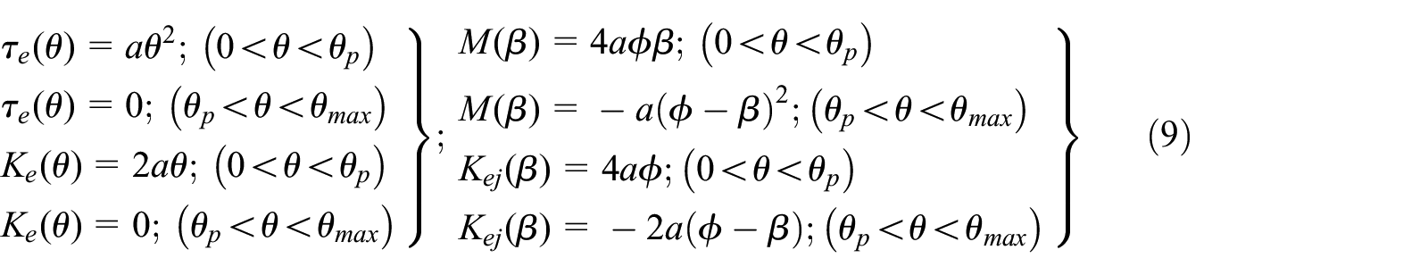
In order to increase the collision safety of the VSJ, the EQTS shown in Figure 14 is designed. The profile curve of the cam is divided into two parts: the first curve can make the EQTS provide elastic torque and the second curve cannot make the EQTS provide elastic torque. The actuation characteristics of the EQTS and the antagonistic VSJ are shown in equation (9). The θp is the maximum angular displacement when the roller is moved along the first cam curve profile. The θmax is the maximum angular displacement of the EQTS when the roller is moved along the second cam curve profile

Conceptual schematic of the fourth type of EQTS.
The spring parameters used in the fifth type of antagonistic VSJ are defined as follows: H0 = 50 mm, d = 3 mm, D = 16 mm, ks = 24.375 N/mm, n = 8, n1=10, smax = 15 mm, λ = 2, and b = 3.125. The parameters of the cam-roller mechanism are defined as follows: rt = 11 mm, rp0 = 34 mm, and αmax = 7°. The angular displacements of the EQTS are defined as θmax = 4.5378 rad and θp = 3.6652 rad, respectively. The maximum elastic torque and output stiffness of the EQTS are τe(θ) max = 4.489 N m and Ke(θ) max = 2.449 N m/rad, respectively. For the fifth type of VSJ, when the angular displacement of the EQTS is less than θp, the elastic torque M(β) of the antagonistic VSJ is from 0 to 4.18 N m, and the joint stiffness range is from 3.1 to 4.9 N m/rad. When the angular displacement of the EQTS is greater than θp, the joint is into the collision safe mode. The actuation characteristics of the EQTS and the fifth type of antagonistic VSJ are shown in Figure 15.

The actuation characteristics of the EQTS and the fifth type of antagonistic VSJ: (a) The characteristics of the EQTS used in the fifth type of antagonistic VSJ and (b) the elastic actuating torque and output stiffness of the fifth type of antagonistic VSJ.
The mechanical solutions of the fifth type of antagonistic VSJ are shown in Figure 16. The (4), the (7), and the (6) are fixed together by the screws. The output position of the joint is measured by the angle encoder (1). The antagonistic driving module of the joint is supported by the two frames (11) and (12). The (11) and the (12) are connected together by the plate (10).
Mechanical solutions of the fifth antagonistic VSJ: (a) Exploded view of the EQTS used in the fifth antagonistic VSJ, (b) exploded view of the antagonistic driving module of the fifth type of antagonistic VSJ, (c) sectional view of the fifth type of antagonistic VSJ, and (d) 2D sectioned view of the fifth type of antagonistic VSJ.
Mechanical structure design of the sixth type of antagonisticVSJ based on the EQTSs
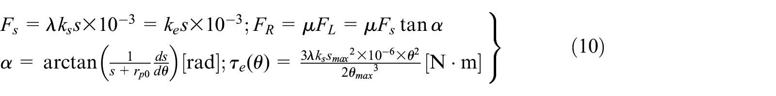
The conceptual layout of the EQTS used in the sixth type of VSJ is shown in Figure 17. The spring force is denoted by Fs, the force applied to the linear guide rod is denoted by FL, the normal force on the cam surface is denoted by Fn, the dynamic friction coefficient between the spring pedestal and the guide rods is denoted by μ, and the FR denotes the frictional resistance exerted on the spring pedestal when the spring pedestal is moved along the linear guide rods. In equation (10), assuming that μ and rp0 are constant. A smaller pressure angle α can be obtained by increasing the θmax or decreasing the smax. Under the same Fs, a smaller frictional resistance can be achieved by reducing the pressure angle α. For the EQTS, in order to ensure a high level of compliance and a high elastic load capacity, the smax is reduced, and the equivalent stiffness ke of the spring set is increased

Conceptual schematic of the EQTS used in the sixth type of antagonistic VSJ.
For this EQTS, the pressure angle is very small. The motion process of the EQTS is relatively smooth with less hysteresis since the frictional resistance is very small. The spring pedestal and the spring set are in the different working plane, and this structure will help to reduce the radial dimension of the EQTS. The parameters of the spring are defined as follows: H0 = 22 mm, d = 1.6 mm, D = 10 mm, ks = 12.943 N/mm, n = 5, n1 = 7, λ = 26, smax = 8 mm, and b = 2.2. For the cam-roller mechanism, rt = 16 mm, rp0 = 36 mm, θmax = 4.5 rad, and αmax = 3.47°. The elastic torque and stiffness of the EQTS are τe(θ) max = 7.179 N m and Ke(θ) max = 3.191 N m/rad, respectively. The maximum angular deflection of the VSJ is βmax = ±2.206 rad. The actuating characteristics of the EQTS and the sixth type of antagonistic VSJ are shown in Figure 18.
The actuating characteristics of the EQTS and the sixth type of antagonistic VSJ: (a) The actuating characteristics of the fifth type of EQTS and (b) the elastic actuating torque and output stiffness of the sixth type of antagonistic VSJ.
The mechanical solutions of the sixth type of VSJ are shown in Figure 19. The bearing cap (1), the bearing (2), and the shaft bushing (4) are used for the axial positioning of the groove cam (3). The roller bearing (6) is mounted on the shaft (7). The (7) is mounted on the roller pedestal (8). The (8) is guided by the linear bearings. The tendon (9) is used to compress the spring set. The bearings (10) and the shaft (11) are assembled together, and they are used for supporting the tendons. The frame (5) and the frame (12) are fixedly connected together. The (10) and the (11) are positioned between the (5) and the (12). The tendon is fixedly connected with the rectangular block (14). When the (8) is moved along the radial direction of the EQTS, the supporting plate (13) is moved along the axial direction of the EQTS. The circular plate (15) is fixedly connected with the (12), and the rectangular flat key (19) is positioned between the (15) and the (12). The bearings (e.g. the (16) and the (21)) and the shaft bushings (e.g. the (17) and the (20)) are used for the axial positioning. The supporting plate (25) is functioning as a stationary frame. The lower EQTS is driven by the gear (23), and the upper EQTS is driven by gear (24) and the rotatable housing (22).

Mechanical solutions of the sixth antagonistic type of VSJ based on the EQTS: (a) Exploded view of the upper EQTS, (b) exploded view of the lower EQTS, (c) exploded view of the antagonistic actuation module, and (d) exploded view of the sixth type of antagonistic VSJ.
Mechanical structure design of the seventh type of antagonisticVSJ based on the EQTSs
The EQTS used in the seventh type of antagonistic VSJ is shown in Figure 20. The main nolvety of this EQTS is that the housing used for placing the spring set can also be used as the output link of the joint. The internal space of the output link is fully utilized. This feature will help reduce the radial dimension of the actuation module, and it is beneficial to the compact design. This EQTS is suitable for use as the elastic element of the swing-type joint. If the output link of the joint is relatively long, the spring with large stiffness and relatively long length can be placed in the interior space of the link. Although the volume of the spring is large, it does not cause too much impact on the overall structure of the joint.

Conceptual schematic of the EQTS used in the seventh type of antagonistic VSJ.
The parameters of the spring set used in the seventh type of antagonistic VSJ are defined as follows: H0 = 22 mm, d = 2 mm, D = 10 mm, ks = 31.6 N/mm, n=5, n1 = 7, b = 2.2, smax = 7 mm, and λ = 21. The parameters of the cam-roller mechanism are defined as rt = 21 mm, rp0 = 45.8 mm, θmax = 4.7124 rad, and αmax = 2.416°. The elastic torque and output stiffness of the EQTS are τe(θ) max = 10.35 N m and Ke(θ) max = 4.3928 N m/rad, respectively. The maximum angular deflection of the joint is βmax = ±2.3126 rad. The actuating characteristics of the EQTS and the seventh type of antagonistic VSJ are shown in Figure 21.

The actuating characteristics of the EQTS and the seventh type of antagonistic VSJ: (a) The characteristics of the EQTS used in the seventh type of antagonistic VSJ and (b) the elastic actuating torque and output stiffness of the seventh type of antagonistic VSJ.
The mechanical solutions of the seventh type of antagonistic VSJ is shown in Figure 22. The bearing cap (1), the bearing (2), and the shaft bushing (4) are used for the axial positioning of the groove cam (3). The left frame (5) and the right frame (9) are fixedly connected together. The roller bearing (6), the roller shaft (7), and the roller pedestal (8) are positioned between the two frames. The two bearings and the two shaft bushings (i.e. the (11) and the (14)) are used for the positioning of the EQTSs. The rectangular flat key (13) is used to transmit the power and position the EQTS on the output shaft (12).

Mechanical solutions of the seventh type of antagonistic VSJ: (a) Exploded view of the EQTS in the seventh antagonistic VSJ, (b) exploded view of the antagonistic driving module of the seventh type of antagonistic VSJ, (c) 2D sectional view of the seventh type of antagonistic VSJ, and (d) CAD assembly of the seventh type of antagonistic VSJ.
Mechanical structure design of the eighth type of antagonisticVSJ based on the EQTSs
The EQTS used in the eighth type of VSJ is illustrated in Figure 23. The spring module having a triangular structure is constructed. The amount of deformation of the spring set is larger than the amount of displacement of the roller pedestal (e.g. s > ΔL). Under the same parameters (e.g. the ks, s, smax, λ, θ, θmax), a smaller pressure angle can be achieved. This feature will help reduce the friction resistance. In addition, the range of angular displacement of the EQTS is increased, and the degree of compliance of the joint equipped with this type of EQTS is improved. The follower motion rule of the cam-roller mechanism is denoted by ΔL(θ), and the total spring force along the y direction is denoted by FRT. The calculation formulas are given in equations (11)–(13)

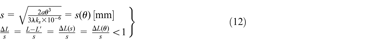


Mechanism schematic of the EQTS for the triangular structure and the tendons configuration: (a) The conceptual structure of the EQTS used in the eighth type of antagonistic VSJ and (b) the equivalent working principle diagram of the EQTS used in the eighth type of antagonistic VSJ.
The parameters of the EQTS used in the eighth type of antagonistic VSJ are listed in Table 9. The parameters of the spring set are defined as follows: H0 = 22 mm, d = 2.5 mm, D = 12 mm, ks = 55.75 N/mm, n = 4, n1 = 6, λ = 12, smax = 5.5 mm, and b = 1.83. The maximum pressure angle of the cam-roller mechanism is αmax = 1.774°. The maximum elastic torque and stiffness of the EQTS are τe(θ) max = 6.324 N m and Ke(θ) max = 2.635 N m/rad, respectively. For the eighth type of VSJ, the initial angular displacement of the EQTS is defined as ϕ = 2.4438 rad, and the maximum angular deflection of the VSJ is βmax = ±2.3562 rad. The actuating characteristics of the EQTS and the eighth type of antagonistic VSJ are shown in Figure 24.
Structural parameters of the EQTS.
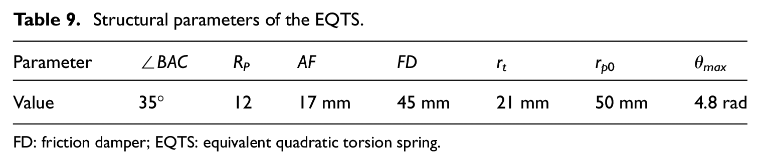
FD: friction damper; EQTS: equivalent quadratic torsion spring.

The actuating characteristics of the EQTS and the eighth type of antagonistic VSJ: (a) The characteristics of the EQTS used in the eighth type of antagonistic VSJ and (b) the elastic actuating torque and output stiffness of the eighth type of antagonistic VSJ.
The mechanical solutions of the eighth type of antagonistic VSJ are shown in Figure 25. The bearing cap (1), the bearing (2), and the shaft bushing (4) are used for the axial positioning of the groove cam (3). The roller pedestal and the spring supporting plate are positioned between the two hollow cylindrical frames (6) and (7). In Figure 19(c), the two bearings and the two shaft bushings are used for the axial positioning of the two EQTSs. The exploded view of the overall assembly of the antagonistic VSJ is shown in Figure 19(d). The first internal ring gear (16) is used to drive the lower EQTS. The second internal ring gear (17) and the rotatable housing (15) are used for driving the upper EQTS. The reducers of the motors are mounted on the fixed supporting plate (18).

Mechanical solutions of the eighth type of antagonistic VSJ: (a) Exploded view of the lower EQTS used in the eighth type of antagonistic VSJ, (b) exploded view of the upper EQTS used in the eighth type of antagonistic VSJ, (c) exploded view of the antagonistic driving module of the eighth type of antagonistic VSJ, and (d) exploded view of the eighth type of antagonistic VSJ.
Mechanical structure design of the ninth type of antagonisticVSJ based on the EQTSs
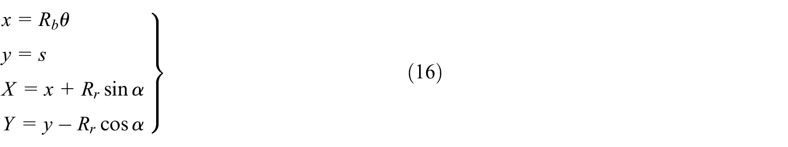
The conceptual model of the EQTS used in the ninth type of antagonistic VSJ is shown in Figure 26. The cylindrical surface of the cam is unfolded into a rectangular plane. The unfolded theoretical curve of the profile is consistent with the displacement curve of the follower. The relative motion trajectory of the center of the roller is represented by δ0. The definitions of the paramaters of the EQTS used in the ninth type of antagonistic VSJ are presented in Table 10.

Mechanism schematic of the EQTS used in the ninth type of antagonistic VSJ: (a) The unfolded profile of the cam and (b) force analysis of the cam-roller mechanism.
Symbols used for schematic description of the EQTS.
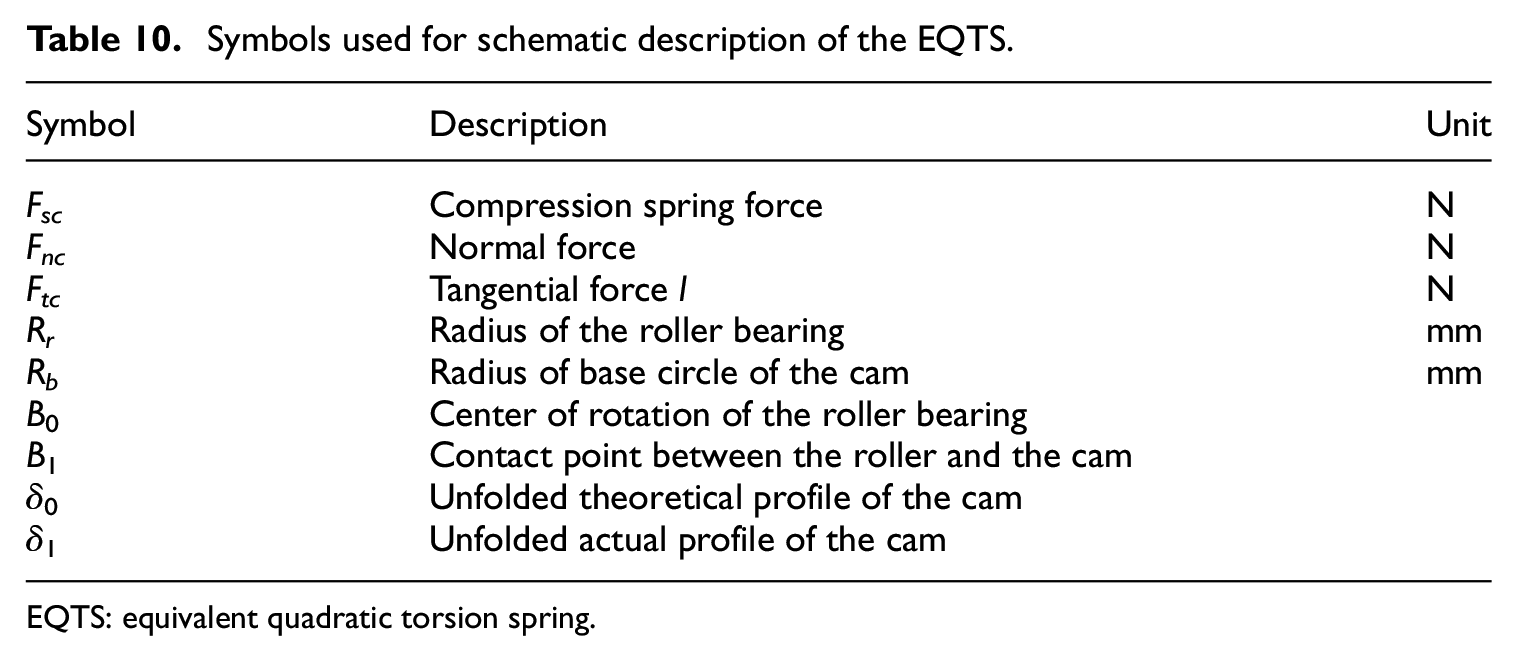
EQTS: equivalent quadratic torsion spring.
The related calculations of the cylindrical cam are expressed in equations (14)–(16)
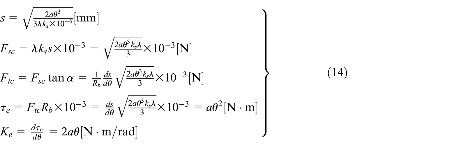

The parameters of the spring used in the ninth type of antagonistic VSJ are defined as follows: H0 = 20 mm, d = 2 mm, D = 10 mm, ks = 31.6 N/mm, n1 = 7, n = 5, λ = 24, smax = 5 mm, and b = 2. The parameters of the cam-roller mechanism are defined as follows: Rr = 13 mm, Rb = 39 mm, αmax = 3.79°, and θmax = 2.9 rad. The maximum elastic torque and stiffness of the EQTS are τe(θ) max = 22.59 N m and Ke(θ) max = 16.69 N m/rad, respectively. The actuating characteristics of the EQTS and the ninth type of antagonistic VSJ are shown in Figure 27.

The actuating characteristics of the EQTS and the ninth type of actuating VSJ: (a) The actuating characteristics of the EQTS used in the ninth type of antagonistic VSJ and (b) the elastic actuating torque and output stiffness of the ninth type of antagonistic VSJ.
The mechanical solutions of the ninth type of antagonistic VSJ are shown in Figure 28. The (18) is fixedly connected to the fixed housing of the joint. The elastic module contains two EQTSs and the transmission elements. The exploded view of the lower EQTS is shown in Figure 28(a). The bearing cap (1) and the bearing (2) are used for the axial positioning of the output shaft (11). The roller bearing (4) and the linear bearing (6) are mounted on the roller pedestal (5). The spring supporting plate (7) is positioned on the output shaft of the joint through the flat key (12). When the cam is rotated, the (5) will be moved along the linear guide (8), and the center torque is generated. In Figure 28(c), the bearings (e.g. the (9) and the (14)) and the shaft bushings (e.g. the (10) and the (13)) are used for the axial positioning of the EQTSs. In Figure 28(d), the internal ring gear (16) is used to drive the lower EQTS. The upper EQTS is driven by the (17). The internal ring gear (17) is connected with the rotatable housing (15).

Mechanical solutions of the ninth antagonistic VSJ: (a) Exploded view of the lower EQTS used in the ninth type of antagonistic VSJ, (b) exploded view of the upper EQTS used in the ninth type of antagonistic VSJ, (c) exploded view of the antagonistic driving module of the ninth type of antagonistic VSJ, (d) exploded view of the ninth type of antagonistic VSJ, and (e) 2D sectional view of the ninth type of antagonistic VSJ.
Conceptual modeling of the 6-DOF robotarm based on the antagonistic VSJ
Comprehensive analysis and comparisons of the eight types of the EQTSs
The conceptual models of the nine types of EQTSs designed in this article are shown in Figure 29. The EQTS-a is the elastic element of the first type of antagonistic VSJ. The range of the angular displacement of the EQTS-a is large, and the elastic load capacity is high. The linear bearings and the roller bearing are used to reduce the frictional resistance. The disadvantage of the EQTS-a is that the volume is relatively large. The antagonistic VSJ equipped with the EQTS-a is suitable for use as the shoulder joint of the robot arm.
CAD assemblies of the eight types of EQTSs: (a) EQTS-a, (b) EQTS-b, (c) EQTS-c, (d) EQTS-d, (e) EQTS-e, (f) EQTS-f, (g) EQTS-g, and (h) EQTS-h.
In the EQTS-b, the tendons are used for transferring the force, and the roller pedestal is guided by the guide groove of the cylindrical housing of the EQTS-b. Although the frictional resistance is increased, the weight of the EQTS-b is reduced. The springs with smaller size are used, and it is beneficial to reduce the radial dimension of the EQTS-b, and the load capacity of the EQTS-b is relatively high since the spring set is used.
In order to reduce the volume of the EQTS and guarantee a high elastic torque output capability, the EQTS-c is designed. Three types of springs with different parameters are used in the EQTS-c. The weight and the dimension of the EQTS-c are reduced, and the elastic load capacity is relatively large. The EQTS-c is suitable for use as the elastic element of the joint which is located in or near the end position of the robot arm.
In order to increase the collision safety of the joint, the EQTS-d is designed. When the roller is moved on the circular arc profile of the cam, the springs inside the EQTS-d will not be compressed, and the actuating torque of the EQTS-d is changed to zero. The EQTS-d is suitable for use as the elastic element of the wrist joint.
In the cam-roller mechanism, a low pressure angle helps reduce the friction. The desired stiffness of the EQTS can be achieved with low hysteresis if the friction is very low. In order to obtain a low pressure angle while ensuring a high elastic load capacity, the working stroke of the spring set is reduced, and the equivalent stiffness of the spring set is increased. Three types of EQTSs are designed based on the method mentioned above. In the EQTS-e, the spring set and the roller pedestal are in the different planes. The moving direction of the roller pedestal is perpendicular to the axial direction of the spring set. This structural feature is beneficial to reduce the radial dimension of the EQTS-e. In order to reduce the axial dimension of the EQTS-e, the small springs with low free height are used to construct the spring set. In the EQTS-f, the housing used to locate the spring set can also be used as the output link of the joint. The EQTS-f is suitable for use as the elastic element of the swing joint. The volume of the EQTS-f is relatively large. Therefore, the antagonistic VSJ equipped with the EQTS-f can be used as the shoulder joint. The main novelty of the EQTS-g is the application of compression spring module having a triangular structure. The amount of deformation of the spring set is larger than the amount of displacement of the roller pedestal. Compared with the previously mentioned EQTSs, the EQTS-g has the minimum pressure angle. The disadvantages of the EQTS-g are that the volume is relatively large.
In the EQTS-h, the spring can be compressed in the axial direction of the EQTS. The radial dimension of the EQTS-h is reduced. This structural feature is beneficial to the compact design. The EQTS-h is suitable for use as the elastic element of the upper arm joint.
Analysis of the nine types of antagonistic VSJs
As shown in Figure 30(a), the VSJ-a (e.g. the first type of antagonistic VSJ) is equipped with a FD. The spring used in the damping mechanism has a large working stroke. Therefore, the damping torque can be changed in a large range. The relationship between the angle of rotation of the damping motor and the damping torque is linear. The elastic load capacity and the compliance of the joint are large. The disadvantage of this joint is that the overall volume and the weight are relatively large. This types of antagonistic VSJ is suitable for use as the shoulder joint.

The antagonistic VSJs based on the EQTSs: (a) VSJ-a, (b) VSJ-b, (c) VSJ-c, (d) VSJ-d, (e) VSJ-e, (f) VSJ-f, (g) VSJ-g, (h) VSJ-h, and (i) VSJ-i.
The conceptual model of the VSJ-b (e.g. the second type of antagonistic VSJ) is shown in Figure 30(b). The use of the combined spring sets will be beneficial to improve the load capacity of the VSJ-b. The FD is used in the joint. The worm gear drive mechanism makes the antagonistic VSJ-b self-locking. However, the weight of the VSJ-b is large. Therefore, the VSJ-b is not suitable for installation in the end of the robot arm. The VSJ-b is suitable for use as the second joint of the robot arm.
Compared with the VSJs mentioned above, the weight and dimensions of the VSJ-c (e.g. the third type of antagonistic VSJ) are reduced. Although the compliance of the joint is reduced, a high elastic load capacity is achieved. Light weight of the joint will help improve the payload of the robot arm. This joint is suitable for installation in the forearm position.
The EQTS-c shown in Figure 29(c) is selected as the elastic element of the VSJ-d (e.g. the fourth type of antagonistic VSJ). The output stiffness of this joint could be adjusted in a faster speed if a reasonable gear ratio is selected. This VSJ is suitable for use as the elbow joint of the robot arm.
The VSJ-e (e.g. the fifth type of antagonistic VSJ) has a relatively large range of angular deflection, and the desired stiffness characteristics of the joint can be achieved with low hysteresis since the friction is very low. The VSJ-e can guarantee the collision safety without an expensive torque sensor. This type of VSJ is suitable for the wrist/elbow joint of the robot arm.
The EQTS-e is selected as the elastic element of the VSJ-f (e.g. the sixth type of VSJ). The EQTS-f is used in the VSJ-g (e.g. the seventh type of VSJ). The EQTS-g is used in the VSJ-h (e.g. the eighth type of VSJ). For the EQTSs used in these three types of joints, the pressure angle of the cam-roller mechanism is very small. A smoother regulation for the output stiffness of the joint can be achieved since the frictional resistance is very small. The VSJ-g is suitable for use as the shoulder joint. The VSJ-f and the VSJ-h can be placed in the forearm position since the elastic load capacity is relatively small.
The EQTS-h is the elastic element of the VSJ-i (e.g. the ninth type of VSJ), and the joint is suitable for installation in the upper arm position (Table 11).
Comparison of the nine types of antagonistic VSJs.

EQTS: equivalent quadratic torsion spring; VSJ: variable stiffness joint.
Conceptual joint configuration schemes of the 6-DOFrobot arm driven by the antagonistic VSJs
As shown in Figure 31, according to the structural characteristics and actuation characteristics of the designed antagonistic VSJs, four types of 6-DOF robot arms are shown. The joint configurations of the robot arms are listed in Table 12.
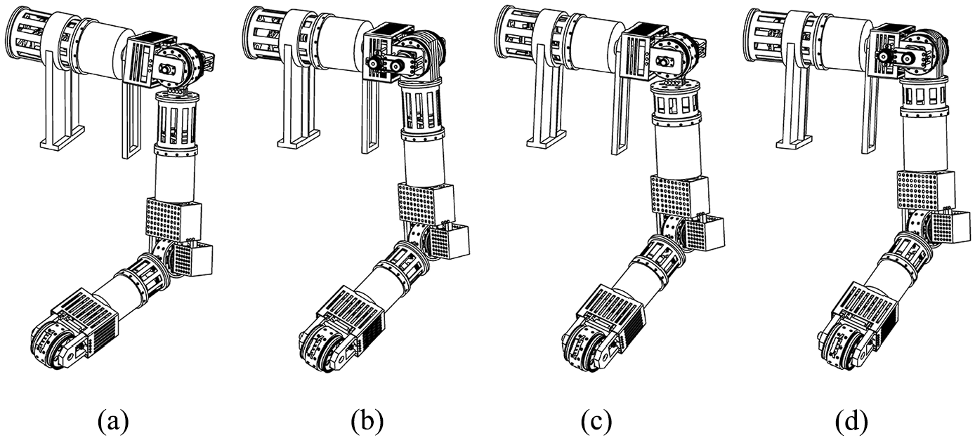
Four types of 6-DOF robot arms: (a) CAD view of the 6-DOF arm-a, (b) CAD view of the 6-DOF arm-b, (c) CAD view of the 6-DOF arm-c, and (d) CAD view of the 6-DOF arm-d.
Joint configurations of the 6-DOF robot arms based on the antagonistic VSJs.

DOF: degrees of freedom; VSJ: variable stiffness joint.
Conclusion and future work
Based on the open design idea, this article designs nine types of antagonistic VSJs based on equivalent nonlinear torsion spring. Taking the EQTS as an example, the design calculation method of the equivalent nonlinear torsional spring with compact structure, large angular displacement range, and desired stiffness characteristics is presented. The detailed CAD views shows the feasibility of the mechanical designs of the antagonistic VSJs. In order to suppress the vibration of the output shaft caused by the elastic element, the FD is designed and added to the antagonistic VSJ. Based on the open design idea, nine types of antagonistic VSJs based on EQTS are designed, and the actuation characteristics of each type of antagonistic VSJ have been illustrated. Finally, four types of joint configuration schemes of the robot arm driven by the antagonistic VSJ are given. This design can provide a reference for the mechanical design of the antagonistic VSJ and the variable stiffness robot arm driven by antagonistic VSJ.
In the future work, we first plan to manufacture the antagonistic VSJ based on the EQTS. In order to reduce the volume and weight of the antagonistic VSJ and improve the actuation reliability of the antagonistic VSJ, the mechanical design software Solidworks, the finite element analysis software ANSYS, and ADAMS software (i.e. automatic dynamic analysis software of mechanical systems) should be used to optimize the mechanical structure design, so as to reduce the weight of the antagonistic variable stiffness robot arm and improve its compactness design. At present, a recursive numerical algorithm to compute the inverse dynamics of multi-DOF robot arm driven by the antagonistic VSJ has been proposed, and the feedback linearization control law is designed to achieve the tracking control of the desired link and stiffness trajectories. 20 Therefore, in the control of the multi-DOF robot arm driven by the antagonistic VSJ, we can refer to the feedback linearization control method. 20
Footnotes
Declaration of conflicting interests
The author(s) declared no potential conflicts of interest with respect to the research, authorship, and/or publication of this article.
Funding
The author(s) received no financial support for the research, authorship, and/or publication of this article.