
Abstract
Introduction:
As an important transportation, the research on the control strategy of forklift has not been widely carried out.
Objectives:
This article proposes a turning slip regulation control strategy, which includes the improved electronic differential velocity control and turning slip regulation control, to track the optimal slip ratio.
Methods:
First, combined with the basic structure and characteristics of dual-wheel-independent-drive electric forklift, the vehicle model, Ackermann–Jeantand steering model, tire-ground model, and tire model of the driving wheel are established respectively. Second, according to these models, an improved electronic differential control strategy considering the influence of vertical load on tire force is proposed and it can reasonably allocate the driving torque of the two driving wheels of electric forklift. Moreover, the optimal slip ratio is given out and the turning slip regulation control strategy, which can track the optimal slip ratio of electric forklift under the conditions of different road surfaces is designed.
Results:
The simulation result and vehicle test show that the control strategy can optimize the slip ratio of electric forklift and greatly improve the stability of electric forklift.
Conclusion:
The turning slip regulation control strategy can be implemented on the TFC35 forklift to improve the safety and stability.
Keywords
Introduction
As a handling equipment, the forklift plays an important role in cargo moving in logistics warehouses, workshops, airports, ports, and other occasions. Compared with the traditional internal-combustion engine (ICE) forklift, the dual-wheel-independent-drive (DWID) electric forklift can control the driving wheels independently and will not be bound by mechanical components.1,2 It means that the torque of two driving wheels can be controlled by different motors separately. DWID simplifies the mechanical structure and enhance the driving performance of forklift simultaneously.3–5 With the purpose of preventing DWID electric forklift from slipping during turning, the turning slip regulation (TSR) control strategy is proposed.
Different from Zhang et al., 6 where a method based on torque vectoring control (TVC) is proposed to improve the maneuverability of a vehicle and the additional yaw moment is analyzed as the key influencing factor in the control system, this article distribute the torque based on the optimal ratio. Feng et al. 7 proposed a control scheme for ISG hybrid electric vehicle, but ignored the effects of the change of roads. In Guo et al., 8 an acceleration slip regulation (ASR) control strategy, which is based on the classification of road conditions and the calculation of the optimal slip ratio for road conditions, is proposed to prevent four-wheel-independent-drive electric vehicle wheels from slipping when they are accelerating. In this article, there are two core contributions for DWID control. The first one is an improved electronic differential control strategy and the second one is the sliding mode optimization strategy for the optimal slip ratio.
This article is organized as follows: The second section gives the dynamic model of DWID electric forklift which includes three-degree-of-freedom vehicle model, Ackermann–Jeantand steering (AJS) model, tire-ground model, and tire model of the driving wheel.9–11 The third section proposes an improved electronic differential control strategy considering the influence of centrifugal force and lateral force on the stability of electric forklift.12,13 In the fourth section, the TSR control strategy based on the sliding mode optimization strategy for optimal slip ratio is designed.14,15 Finally, the TFC35 electric forklift controlled by DWID was used as the research object and the experiment result proves the effectiveness of the method in the fifth section.
Electric forklift dynamics model
According to the mechanical characteristics and parameters of the TFC35 electric forklift produced by Hefei Banyitong Science and Technology Development Co. Ltd., the vehicle model, the AJS model, the tire-ground model, and the tire model of the driving wheel are established, respectively. The differential equations of kinematics are deduced correspondingly.
The vehicle model
The front wheels of TFC35 electric forklift controlled by DWID are steering wheels, while the rear wheels are driving wheels. It is assumed that the movements of the electric forklift are the longitudinal movement along the X-axis, the lateral movement along the Y-axis, and the yaw movement around the Z-axis. Figure 1 is the coordinate system of the DWID electric forklift and Figure 2 is the dynamic model of the DWID electric forklift.
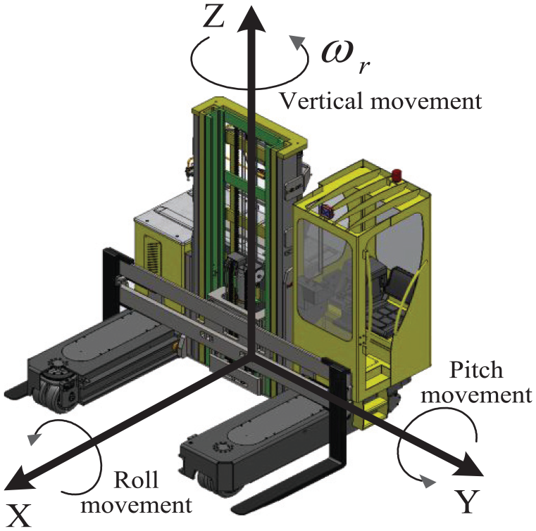
The coordinate system of the DWID electric forklift.
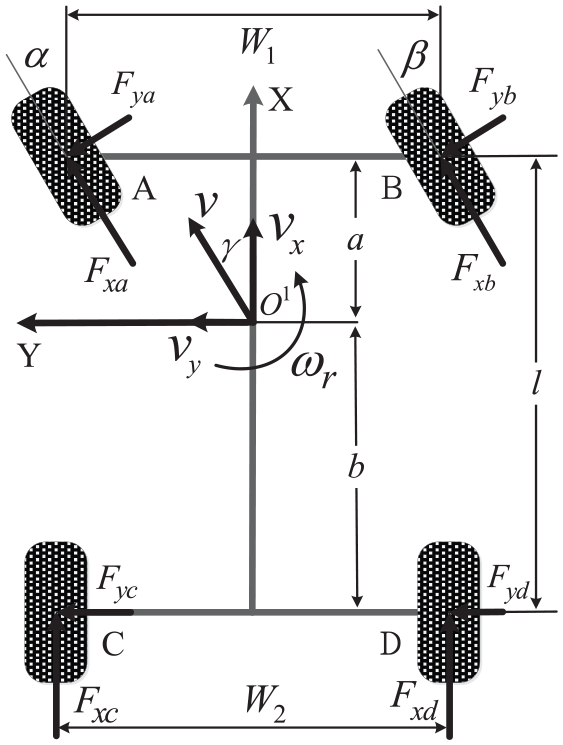
The dynamic model of the DWID electric forklift.
According to Newton–Euler equations, the kinematic differential equations, which include the roll movement around the X-axis, the pitch movement around the Y-axis, and the vertical movement around the Z-axis, are established as follows:


where
The AJS model
For DWID electric forklift, to achieve the optimum control of driving torque of two driving wheels, the speed of two driving wheels and the steering angle of the vehicle should be given. Generally, the tire speed outside is greater than that of the inner when the forklift turns around according to vehicle kinematics theory. To achieve the electronic differential control strategy for DWID electric forklift, the steering models are established as shown in Figure 3, according to Figure 2 and AJS theory, where,

The AJS model of the DWID electric forklift.
According to this model, the speed of each tire can be got according to the electronic differential control strategy. The driving torque of each driving wheels can be derived based on the attachment rate, slip ratio, and the actual situation of electric forklift load.
As shown in Figure 3, the formulas can be derived as:


The two driving wheels’ speed can be calculated as:


where
The tire-ground model
Although the driving force of the driving wheel hinges on the driving torque of the driving motor mainly, it will also be affected by the conditions attached to the ground. Generally, there is a certain relationship between the coefficient of adhesion and the slip ratio as shown in Figure 4. The longitudinal adhesion coefficient will increase sharply when the slip ratio is small, the adhesion coefficient will reach an extreme point as the slip ratio increases to a certain value (generally between 0.1 and 0.3). But if the slip ratio keep increasing, the adhesion coefficient will fall. At the same time, lateral adhesion coefficient decreases rapidly as slip ratio increases. Considering the dynamic performance and lateral stability of the electric forklift, the optimal slip ratio of electric forklift should be within the range which is slightly less than the slip ratio at peak point.

The relationship between the adhesion coefficient and the slip ratio.
Hyperbolic model is adopted to calculate the adhesion coefficient of tire. It can be represented by:

where
As shown in Figure 4, the slip ratio has a great influence on the longitudinal adhesion coefficient and lateral adhesion coefficient of tires and also affects the driving and braking performance of the electric forklift.
The improved electronic differential control strategy
The electronic differential control is a differential method where the driving speed of each driving wheel meets a certain constraint in a pure software manner. And the rotation speed of each wheel is completely controlled by an electronic control method.
To design the improved electronic differential control strategy, the AJS model is used to analyze the stability, the assumptions of this model are given as follows: (1) the vehicle can be regard as a rigid body; (2) the movement of the tire is pure scroll; and (3) the impact of tire deformation for the movement is ignored.
Combined with equations (10) and (11), the rotation angular velocity of two driving wheels can be derived as:

where
In condition of above assumptions, the ratio of tire speed inside to tire speed outside is equal to the ratio of the turning radius. However, this is the idealized steering model which only considers the static analysis of the moving status. In fact, the tire itself, the centripetal force and the centrifugal force produced by turning should also be considered. At the same time, the tire is easy to slip in actual movement according to the traditional electronic differential control strategy because it only involves the speed of the driving wheels, while the lateral force and slip ratio are not considered.
The improved electronic differential velocity controller
The improved electronic differential velocity algorithm considers the vertical load changes on the wheel 17 as well as the impact of centrifugal force on the electric forklift. 18
It is assumed that the vertical load of left driving wheel is same as the right when the electric forklift drives straight or remains stationary:

where
When the electric forklift turns around, the centrifugal force (tire lateral force) and the rollover torque are:


Therefore, when the electric forklift turns around, the vertical load of two driving wheels are given as follows:

Based on the electric forklift DWID dynamics model, the torque ratio of the two driving wheels can be obtained by:

where
According to the torque ratio of two driving wheels, the difference between the driving motor torque of the driving wheel inside and outside can be calculated as:

According to the improved electronic differential velocity algorithm, the driving torque of the two driving wheels of the electric forklift can be represented by:

Simulation and analysis of DWID electronic differential control strategy
The improved electronic differential velocity algorithm takes the change of vertical load on the wheel and the impact of centrifugal force on the electric forklift into consideration.
Model the TFC35 electric forklift in MATLAB/Simulink and the parameters for the vehicle model are shown in Table 1.
Main parameters for the vehicle model.

It is assumed that the velocity varies from 0 to 8 km/h and the rotation angle varies from 0 to 1 rad, then the relationship among the torque ratio of driving wheel, the velocity, and the rotation angle is shown in Figure 5.

The relationship among the torque ratio of driving wheel, the velocity, and the rotation angle.
The ordinary vehicles adopt the mechanical differential to change the speed of the wheels and the drive torque cannot adjust according to the real-time speed of the vehicle. Therefore, the vehicle is difficult to work in the optimal range of slip ratio. From Figure 5, the improved electronic differential velocity control strategy can effectively distribute the torque of two driving wheels and improve the stability of electric forklift. On the other hand, the distribution relation above also can be validated according to the relation among the yaw rate, velocity, and rotation angle.19,20
As shown in Figure 6, the yaw rate will increase with the increase of velocity under a certain steering wheel angle. However, the acceleration of yaw rate will decrease which will not only make the electric forklift more stable at low speed, but also avoid steering wheel too sensitive at high speed. Therefore, the improved electronic differential velocity control strategy is beneficial to improve the stability of forklift.

The relationship between yaw rate and the forklift velocity.
TSR control strategy
According to the SMC and extremum-seeking algorithm, the sliding mode extremum-seeking controller for slip ratio is proposed. It adopts a self-optimization method to search for the slip ratio (i.e. the optimal slip ratio) at the extreme point of the tire force–slip ratio characteristic curve and ensures that the driving wheel can obtain greater longitudinal adhesion and lateral adhesion simultaneously.21,22 Based on the algorithm, the TSR control strategy is presented.
The sliding mode extremum-seeking controller for slip ratio
The sliding mode extremum-seeking controller is designed to track the optimal slip ratio under the condition of real-time road surface. The tracking vector of the sliding mode controller can be defined as the error of the target slip ratio and the real-time slip ratio:

It means that the tracking error
The sliding mode surface of the controller is defined as:

Combined with the longitudinal force of the DWID electric forklift

and its time derivative is calculated as:

Define the first derivative of slip ratio as the control law:

where k and σ are positive constants. k represents the convergence rate of the system and σ mainly affects the switching frequency of sliding mode control. Substituting equation (25) into equation (24), we can get:

where


As

Then the inequality can be got as follows:

According to Lyapunov reachable condition of sliding mode control,

Equation (31) can be transformed into:

It means when
2.

Thus, we can also get that when
Then, the reachable condition of equation (26) can be defined as:

Based on the analysis above, we can get:

From equation (35), the longitudinal force
From the analysis above, we can get that when the value of slope is greater than
Desired driving torque with optimal slip ratio
The dynamic model of driving wheel is shown in Figure 7. 8 In terms of the driving principle and Figure 7, the dynamic model of driving wheel can be expressed as shown in equation (36):

where

The dynamic model of driving wheel.
The rolling resistance

Define the rolling resistance coefficient as

The longitudinal force of wheel can be expressed as the product of the wheel load and the adhesion coefficient of the road surface:

From equation (38), we can obtain:


The derivative of equation (41) is:

The slip ratio of the tire is defined as:

And the derivative of equation (43):

According to equations (42) and (44), we can get:

where
From equation (38), we can get:

Substituting equation (46) into equation (44), we can get:

Combined with equation (25), the desired driving torque can be expressed by:

TSR control strategy
The block diagram of the proposed TSR control strategy is shown in Figure 8. Due to the longitudinal force cannot be measured by the sensor, the tire longitudinal force sliding mode observer is constructed. 24 The velocity of vehicle v and rolling angular velocity of driving wheel ω can be measured by the corresponding sensors.

Block diagram of TSR control strategy.
As shown in Figure 8, TSR control strategy can be divided into two parts. One is the improved electronic differential velocity control. Based on the vehicle velocity and the steering angle
Simulation and experiment results
Simulation results and analysis
To verify the TSR control strategy for the slip ratio, some simulations are built in MATLAB/SIMULINK. The vehicle speed is 3 m/s, the steering angle of forklift is 0.087 rad, and simulation results are shown in Figures 9–12.
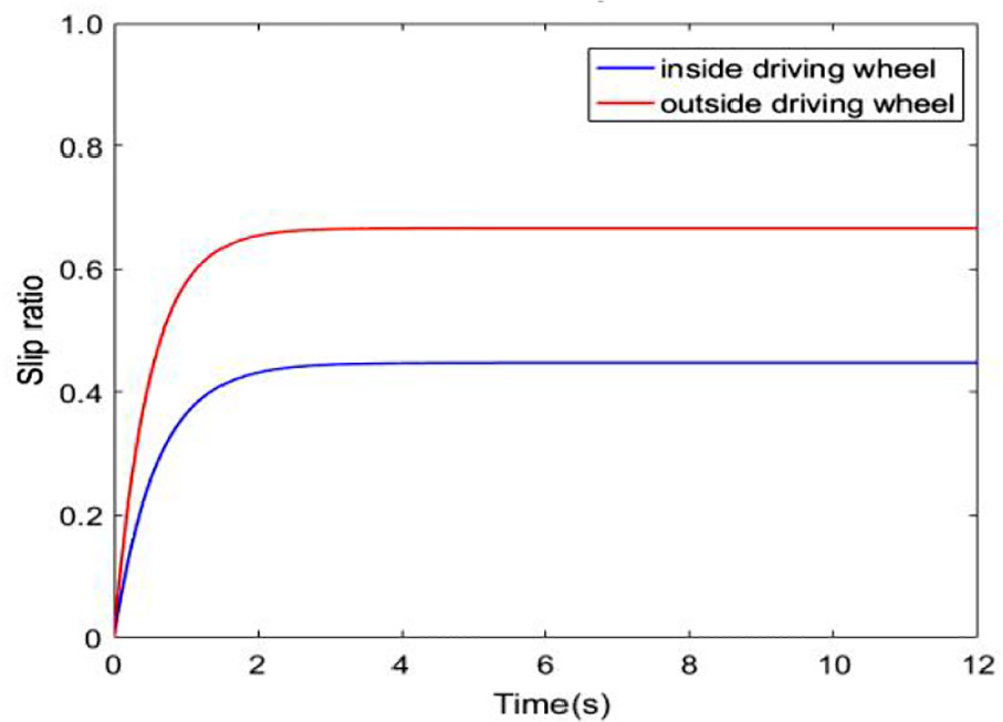
The slip ratio under no controller.

The slip ratio under TSR controller.

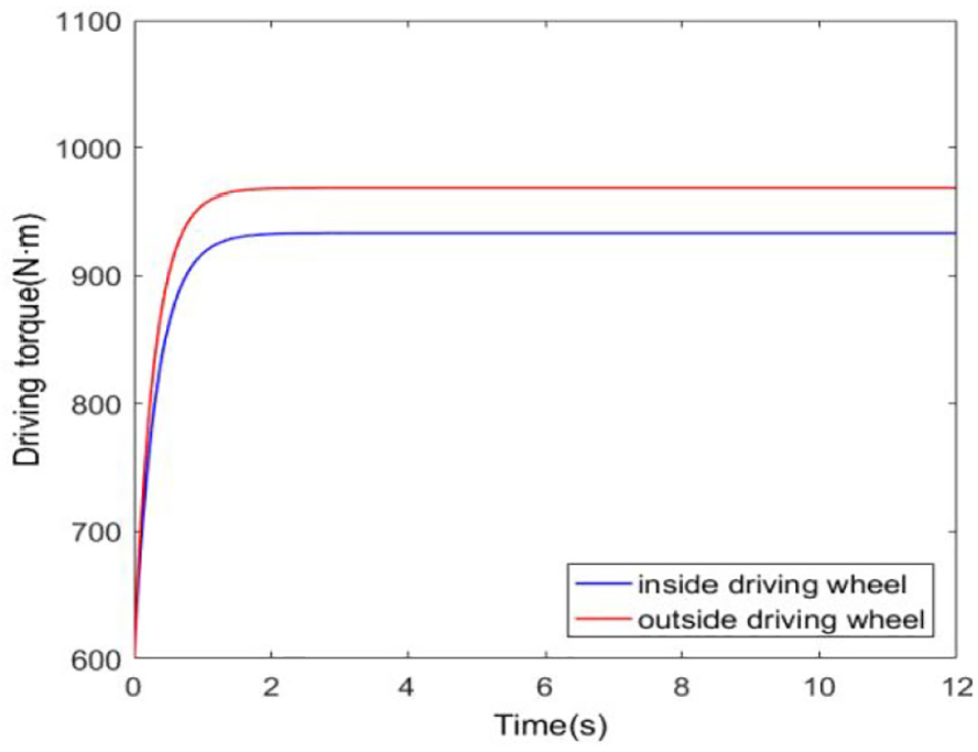
The driving torque under no controller.
The driving torque under TSR controller.
As shown in Figure 9, it can be seen that the slip ratio of the inside driving wheel is obviously less than that of outside driving wheel under no controller. It means that the forklift is easy to slip and tires can be badly worn.
As shown in Figure 10, it can be seen that after a short period of optimization, the slip ratio of the inside driving wheel is basically consistent with that of outside driving wheel under TSR controller. It means that the stability of the forklift have been greatly improved. The slip ratio of the two driving wheels is 0.2 which is within the slip ratio optimal range.
As shown in Figures 11 and 12, we can see that to search the optimal slip ratio, the driving torque will vary based on the change of slip ratio.
To further verify the stability of the TSR control strategy, the responses of side-slip angle and yaw rate are shown in Figures 12 and 13, respectively. And three kinds of systems will be simulated as follows:
System without control
System with general electronic differential control
System with TSR control

The change curve of side-slip angle.
The electric forklift drives straight for 2 s under the speed of 4 km/h, and then input a sinusoidal signal.
As shown in Figures 13 and 14, the side-slip angle with TSR control is much smaller than that under no control and general control. The simulation results show that compared with no control and general control, TSR control can improve the stability of the electric forklift effectively.

The change curve of yaw rate.
Experiment results
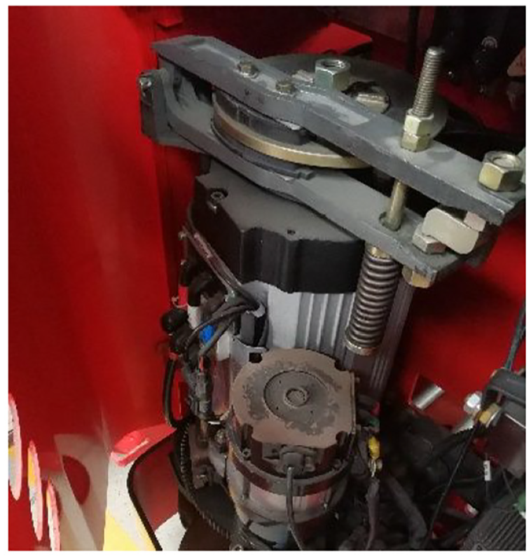
TFC35 electric forklift is shown in Figure 15. The driving motor is shown in Figure 16, it is a 5.5 kW AC motor and its rated power is 48 V. First, accelerate TFC35 to about 10 km/h, and the forklift turns left at a constant speed of 5°, the response of current while steering under no control is shown in Figure 17 and that under TSR control is shown in Figure 18.

The TFC35 experimental electric forklift.
The TFC35 experimental electric forklift.

The driving motor of TFC35.

The response of current under TSR control.
As shown in Figure 16, it can be seen that under no controller, the current of outside driving wheel motor and inside driving wheel motor differs greatly which represent the driving torque of the two driving wheels. It means that the slip ratio differs greatly, the electric forklift will move with low stability.
As shown in Figure 17, it can be seen that under TSR control, the current of outside driving wheel motor and inside driving wheel motor are very close. At the same time, the slip ratio is relatively close and within the range of optimal slip ratio, which means that the electric forklift has a better dynamic performance.
Conclusion
DWID electric forklift is a new type of electric forklift, where two separate driving motors are used to drive the driving wheels. It can get rid of mechanical restraint and provide the driving wheels with suitable driving torque.
Based on the basic structure and characteristics of TFC35 DWID electric forklift, the vehicle model, AJS model, tire-ground model, and tire model of the driving wheel are established. These mathematical models provide the theoretical basis for the research on TSR control of electric forklift. On the basis of traditional electronic differential velocity, an improved electronic differential velocity control strategy, considering the influence of vertical load on tire force, the centrifugal forces and the tire lateral forces, is designed. To track the optimal slip ratio, the TSR control strategy based on the sliding mode extremum-seeking algorithm is designed. The simulation and experiment results show that the TSR control strategy can not only control the slip ratio of forklift near the optimum value, but also ensure the stability of the DWID electric forklift.
Footnotes
Acknowledgements
This work is supported by Hefei Banyitong Science and Technology Development Co. Ltd., the authors are grateful to senior engineer Junliang Guo, Zijian Fang, Pengfei Li, Xingzhi Fang, and Weilin Lv for their cooperation and helpful suggestions. Besides, the authors extend their sincere thanks to graduate students Junjie Huang, Zhizheng Jiang, Xu Zhang, and Chenggong Sun in the same study room.
Declaration of conflicting interests
The author(s) declared no potential conflicts of interest with respect to the research, authorship, and/or publication of this article.
Funding
The author(s) disclosed receipt of the following financial support for the research, authorship, and/or publication of this article: This work was supported by the National Natural Science Foundation of China (grant no.: 51577046), the State Key Program of National Natural Science Foundation of China (grant no.:51637004), and the national key research and development plan “Important Scientific Instruments and Equipment Development” (grant no.: 2016YFF0102200).