
Abstract
To solve the problems that the borehole depth is shallow and the drilling efficiency is low during the gas drainage drilling in soft coal seam with current cuttings removal method, a new technology of reverse circulation pneumatic cuttings removal is proposed. The working principle of reverse circulation pneumatic cuttings removal is analyzed, and the kinetic equation of cuttings in the inner hole of the drill pipe is established. Through experiments, the pressure drop in the drill pipe is measured to reveal the effects of air velocity, cuttings mass flow rate, and cuttings particle size on the pressure drop in inner hole of the drill pipe. When the cuttings mass flow rate is constant, the pressure drop increases with the increase in air velocity. When the air velocity is constant, the pressure drop increases with the increase in cuttings mass flow rate. At low air velocity, the pressure drop of cuttings is primary. As the air velocity increases, the pressure drop ratio of cuttings decreases. Under the same conditions, the order of pressure drop with different particle size cuttings is coarse cuttings > medium cuttings > fine cuttings. Empirical equation of pressure drop coefficient of cuttings is established, which is in good agreement with the actual data.
Keywords
Introduction
In coal and gas outburst mines, the pre-drainage of coal seam gas by drilling along the coal seam is one of the main regional outburst prevention measures for coal roadway driving and coal seam mining. During the drilling construction, the drill cuttings removal is the key to ensure the drilling depth and the drilling efficiency. 1 During the drilling in soft coal seam, mechanical removal and hydraulic removal of cuttings have a great impact on the stability of the borehole wall, which is easy to cause the borehole collapse and blockage, sticking of the drill pipe, and other accidents. The traditional pressure air removal of cuttings method removes the cuttings through the annular space between the drill pipe and the borehole wall by the pressure air through the inner hole of the drill pipe. It is difficult to collect the drill cuttings at the outlet of the borehole, which is easy to cause the dust pollution.2–4 So, a new reverse circulation pneumatic cuttings removal technology proposed that the annular space between the drill pipe and the borehole wall is used as the air inlet and the inner hole of the drill pipe is used as the cuttings removal channel.5,6
The reverse circulation technology was first applied to the geotechnical drilling. Strauss et al. 7 reviewed several case studies that the dual-wall air reverse circulation was applied in ground water exploration in Southern California. Livingstone 8 proposed a reverse circulation method for drilling a wellbore in hydrocarbon formation using the concentric drill pipe. Gan et al. 9 designed a large-diameter reverse circulation drill bit for oil and gas exploration which improved the average penetration rate. Some researchers applied the reverse circulation technology to the wellbore cleaning. Kumar et al. 10 attempted to use coiled tubing reverse circulation for cleaning petroleum horizontal wells, and an average increase in 15% in water injection rate was improved. Ozbayoglu et al. 11 proposed a layered cuttings transport model for high-angle and horizontal wells and analyzed the effects of major drilling parameters, such as flow rate, fluid density, and gas ratio, on cuttings transport efficiency. Boyou et al. 12 investigated the performance of nanosilica water-based drilling fluids for the hole cleaning process in directional drilling operations. The presence of nanosilica in mud increased the colloidal interactions with cuttings, and the cuttings transport efficiency was improved. Dong et al. 13 applied the reverse circulation technology during the reaming process and developed a novel reverse circulation reamer.
There are some applications in mines. Zhang Hui et al. 14 developed a pump suction reverse circulation drilling system and carried out experimental research, which solved the drilling problem of anchor cable hole in the roadway floor and purified the working environment. Hui and Chao 15 combined the reverse circulation technology with the negative pressure drilling process to study the influence of negative pressure, drill pipe inner diameter, and drilling angle on the drill cuttings removal distance. Based on the analysis of the fixed-point sampling method and its drawbacks in the gas content determination of coal seam at present, Hongtu Zhang et al. 16 applied the reverse circulation technology to the fixed-point sampling and proposed a negative pressure fixed-point sampling method. Zhihui Wen et al. 17 used the negative pressure fixed-point sampling technology to carry out the field experiments and obtained the calculation method for the gas content loss. Jianping Wei et al. 18 simulated the cuttings–air two-phase flow in the negative pressure fixed-point sampling equipment and analyzed the transport law of the drill cuttings.
These successful applications provide the motivation to propose the reverse circulation pneumatic cuttings removal technology during the gas drainage drilling in soft coal seam. The method can avoid the disturbance to the borehole wall and improve the cuttings removal efficiency. At the same time, the drill cuttings transported through the inner hole of the drill pipe can be collected conveniently to avoid the coal dust pollution. In this article, according to the working principle of reverse circulation pneumatic cuttings removal, the force and the movement of drill cuttings in the inner hole of the drill pipe were studied and the pressure drop characteristics in the inner hole of the drill pipe were analyzed experimentally.
Theoretical analysis of reverse circulation pneumatic cuttings removal
System composition and working principle
The reverse circulation pneumatic cuttings removal system mainly includes the drilling rig, drill pipe, drilling bit, cyclone separator, and Roots vacuum pump, as shown in Figure 1.

Reverse circulation pneumatic cuttings removal system.
The Roots vacuum pump provides the air force for the pneumatic conveying of drill cuttings. Under the suction effect of Roots vacuum pump, air enters the bottom of the borehole along the annular space between the drill pipe and the borehole wall. The drill cuttings generated by the operating bit are wrapped and carried into the inner hole of the drill pipe through the discharge hole. And the inner hole of the drill pipe is used as the cuttings removal channel. The cyclone separator acts as the dust removal device to separate the drill cuttings from the cuttings–air two-phase flow. The drill cuttings are collected in the separator under the gravity while the filtered air is discharged through the Roots vacuum pump. In the process of cuttings removal by the system, the resistance of the cuttings in the inner hole of the drill pipe is small and the cuttings removal efficiency is high. At the same time, the system plays a role of dust control and dust suppression by collecting the discharged cuttings.
Kinetic analysis of cuttings in the inner hole of the drill pipe
During the movement in the inner hole of the drill pipe, the drill cuttings are not only subjected to their own gravity

Forces and motions of the cuttings in the inner hole of the drill pipe.
The aerodynamic thrust from the airflow is


where
The resistance of the inner hole wall in the drill pipe is


Substituting equation (4) into equation (3)

where

So, the cuttings gravity in the

When the drill cuttings are in suspension state, the cuttings resistance coefficient
where
According to the fluid mechanics, the resistance is divided into three regions according to the Reynolds number

In the state of suspension, the drill cuttings are subjected to the aerodynamic thrust which is the sum of their buoyancy and gravity. Since the density of the drill cuttings is much larger than that of air, the buoyancy can be neglected. So


According to Newton’s second law, there is

Substituting equations (5), (7), and (12) into equation (13)

Equation (14) describes the relationship between the cuttings velocity and the cuttings movement time.
In different resistance zones,

During the reverse circulation pneumatic cuttings removal,
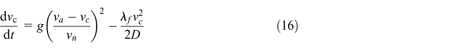
Taking the drill cuttings with the particle size of 1 mm as the research object, the air velocity vn = 9 m/s and the gravity acceleration g = 9.8 m/s2 are taken, and vc = 0 m/s is used as the initial condition of the differential equation when t = 0 s. Equation (16) is solved under different air velocity

Influence of

Influence of

Influence of D on variation of
Figure 3 shows the variation of cuttings velocity with time when the resistance coefficient is
It can be seen from the graphs that the drill cuttings accelerate first and then move uniformly. Equations (1) and (5) show that the aerodynamic thrust
The acceleration section of the drill cuttings mainly concentrates in the time of 0–1 s and in the distance of 0–3 m, which indicates that the acceleration process of drill cuttings is very short. The change of air velocity has a great influence on the cuttings acceleration in the acceleration section and the cuttings velocity in the uniform velocity section. With the increase in air velocity, the aerodynamic thrust of cuttings becomes large. So, the cuttings acceleration in the acceleration section and the cuttings velocity in the uniform velocity section increase. Under a certain air velocity, the velocity difference between the air velocity and the cuttings velocity gradually decreases in the process of cuttings acceleration. And the aerodynamic thrust of drill cuttings decreases. Therefore, the cuttings acceleration in the acceleration section gradually decreases with time and distance.
Figure 4 shows the variation of cuttings velocity with time when the air velocity is
As can be seen from Figure 4, the resistance coefficient of the inner hole wall of the drill pipe mainly affects the cuttings velocity in the uniform velocity section. With the increase in the resistance coefficient, the cuttings velocity in the uniform velocity section decreases. Equation (5) shows that the inner hole wall resistance of the drill pipe is positively correlated with the resistance coefficient. The increase in the resistance coefficient makes the inner hole wall resistance of the drill pipe larger. Accordingly, a larger aerodynamic thrust is needed to balance the inner hole wall resistance of the drill pipe, which requires a larger velocity difference between the airflow and drill cuttings. Therefore, the increase in the resistance coefficient will lead to the decrease in the cuttings velocity in the uniform velocity section.
Figure 5 shows the variation of cuttings velocity with time when the resistance coefficient is
From Figure 5, it can be seen that the change of the internal diameter of the drill pipe has less influence on the cuttings in the acceleration section and more obvious influence on the cuttings in the uniform velocity section. The increase in the internal diameter of the drill pipe can increase the cuttings velocity in the uniform velocity section. But the effect of increasing the internal diameter of the drill pipe on the cuttings velocity in the uniform velocity section is gradually weakened. Considering equation (5), it can be seen that the inner hole wall resistance of the drill pipe is negatively correlated with the internal diameter of the drill pipe. The inner hole wall resistance of the drill pipe decreases with the increase in the internal diameter of the drill pipe. The corresponding aerodynamic thrust used to balance the inner hole wall resistance of the drill pipe decreases, and the velocity difference between the airflow and cuttings decreases. Therefore, the increase in the internal diameter of the drill pipe leads to the increase in the cuttings velocity in the uniform velocity section.
In summary, to improve the cuttings velocity in the uniform velocity section, the air velocity and the internal diameter of the drill pipe can be increased, while the resistance coefficient of the inner hole wall of the drill pipe can be reduced. When the outer diameter of the drill pipe is constant, increasing the internal diameter of the drill pipe can increase the cuttings velocity in the uniform velocity section, but this will reduce the wall thickness of the drill pipe and the strength of the drill pipe, which will easily lead to the fracture accident of the drill pipe during drilling in the coal seam. In addition, increasing the internal diameter of the drill pipe will gradually weaken the effect of increasing the cuttings velocity in the uniform velocity section. Therefore, on the basis of guaranteeing the strength of the drill pipe, the internal diameter of the drill pipe should be appropriately enlarged to increase the cuttings velocity in the uniform velocity section. At the same time, the kinetic analysis results provide the basis for the selection of experimental parameters and the installation of test sensors in the experimental work.
Experimental study of reverse circulation pneumatic cuttings removal
Test system
The reverse circulation pneumatic chip evacuation test device is shown in Figure 6.

Experiment system of reverse circulation pneumatic cuttings removal.
During the actual drilling in soft coal seam, the drilling bit with the external diameter of 94 mm is used widely. So, the internal diameter of the simulated borehole is selected as 100 mm considering the reaming effect of the bit. The size of the simulated drill pipe is same with the actual drill pipe in which the internal and external diameters are 40 and 73 mm, respectively. The Roots vacuum pump typed of QZSR125A is used as the power source of the experimental system. The boost range is −50 to 0 kPa and the maximum flow is 6.38 m3/min. During the test, the flow of Roots vacuum pump can be changed by adjusting the speed of the variable frequency motor of Roots vacuum pump to adjust the air velocity. A feeding device is used to simulate the generation of drill cuttings. The feeding device is composed of bunker and screw conveyor. The mass flow rate of the cuttings is controlled by adjusting the speed of the screw conveyor. The transparent rigid plexiglass tube is used to simulate the drill pipe and the borehole. The two-phase separation of the drill cuttings and air is completed in the cyclone separator. Figure 7 is the actual experimental equipment.

Experimental equipment. (a) Feeding device. (b) Cuttings removal channel. (c) Separator and vacuum pump.
During the test, the pressure in the inner hole of the drill pipe is measured. The pressure signal acquisition system is shown in Figure 8. The pressure signal acquisition adopts YZ1210 high-precision diffused silicon pressure sensor, which is powered by 24 V DC. The range of the sensor is −15 to 0 kPa, and the precision is ±0.25% full span (FS). The output voltage signal is collected by the YSV dynamic signal acquisition instrument. The frequency of signal acquisition is 1000 Hz. The collected signal is displayed and analyzed by the computer. To reduce the experimental error, the pressure sensor was calibrated before the test, and the average value of the measured pressure is taken. At the same time, there are two pressure measuring points in the simulated drill pipe. According to the theoretical analysis, the acceleration process of the drill cuttings mainly occurs in 0–3 m section. To obtain the accurate pressure drop characteristics, the pressure drop test must be carried out in the uniform velocity section in the drill pipe. So, the pressure measuring point 1 is set at the distance of 3 m from the drill pipe inlet, and the pressure measuring point 2 is set at the downstream 2 m from the pressure measuring point 1.

Signal acquisition system.
Test materials and schemes
The test material is the raw coal cuttings. To analyze the influence of the particle size of cuttings on the pressure drop in the inner hole of the drill pipe, the raw coal cuttings were divided into three kinds of cuttings with different particle size using the screen mesh with screen sizes of 1.70, 1.18, and 0.85 mm, respectively. The screened cuttings are called fine cuttings, medium cuttings, and coarse cuttings according to their particle size. The related parameters are shown in Table 1.
Experiment material parameters.

The true density of coal is 1400 kg/m3 and the drilling speed is generally 0.3–0.8 m/min. 19 So, the mass flow rate of the cuttings is 0.055–0.147 kg/s. In the experiment, the mass flow rate of the cuttings was selected as 0.06, 0.08, 0.10, 0.12, and 0.14 kg/s, and the air velocity was selected as 15, 20, 25, 30, and 35 m/s. A total of 75 groups of experiments were carried out.
Test results and analysis
Pressure drop in the inner hole of the drill pipe with the pure airflow field
The pressure drop in the inner hole of the drill pipe in the pure airflow field refers to the pressure drop caused by the airflow in the inner hole of the drill pipe without cuttings, which is mainly the friction pressure drop of the airflow. The analysis of the pressure drop in the inner hole of the drill pipe with the pure airflow field is to analyze the composition of the pressure drop in the inner hole of the drill pipe during the cuttings removal. Figure 9 shows the pressure values at measuring point 1 and measuring point 2 in the pure airflow field at different air velocity. The maximum relative error is about 8.93% which meets the test requirements.

Pressure at measuring points in the pure airflow field.
From Figure 9, it can be seen that the pressure values at each measuring point are negative pressure under the suction action of Roots vacuum pump. The negative pressure values of each measuring point increase with the increase in air velocity. At the same time, the negative pressure value at measuring point 2 is higher than that at measuring point 1, which indicates that the farther from Roots vacuum pump, the lower the negative pressure value. When the distance from Roots vacuum pump is relatively long, the negative pressure value will be too low. The ability of airflow to carry cuttings will be weakened. Therefore, the selection of Roots vacuum pump should also consider the influence of drilling depth in coal seam.
Figure 10 shows the pressure drop per unit length between measuring point 1 and measuring point 2 in the pure airflow field. It can be seen that the pressure drop in the inner hole of the drill pipe in the pure airflow field increases with the increase in air velocity, which indicates that the higher the air velocity, the greater the friction pressure drop caused by the airflow in the inner hole of the drill pipe.

Pressure drop in the pure airflow field.
Pressure drop in the inner hole of the drill pipe during cuttings removal
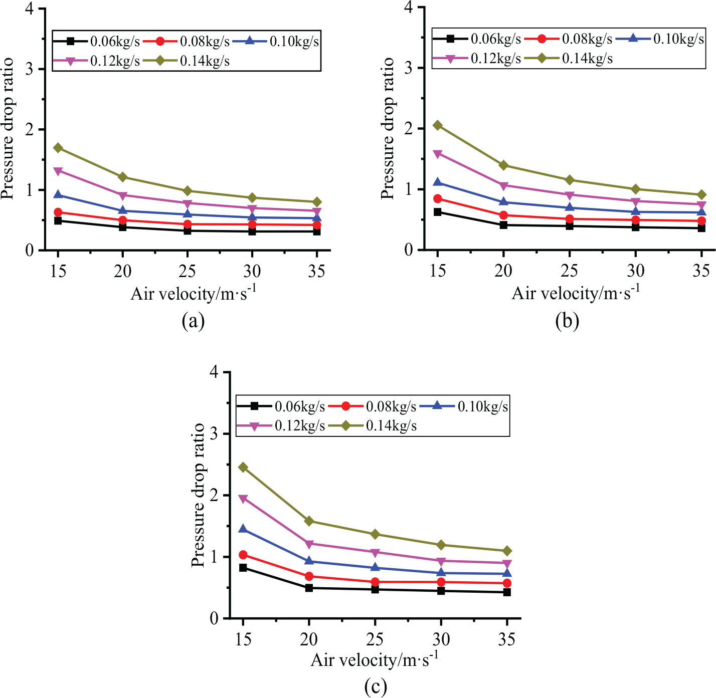
The pressure drop of three kinds of cuttings with different particle size in the inner hole of the drill pipe is shown in Figure 11 under different air velocity and mass flow rate of cuttings. As can be seen from Figure 11, the variation characteristics of the pressure drop in the inner hole of the drill pipe with different particle size cuttings during cuttings removal are the same. When the mass flow rate of cuttings is constant, the pressure drop in the inner hole of the drill pipe increases with the increase in air velocity. Under the same air velocity, the increase in mass flow rate of cuttings will lead to the increase in the pressure drop in the inner hole of the drill pipe. With the increase in air velocity, the difference of pressure drop under different mass flow rate of cuttings increases. In addition, by comparing the pressure drop values in the inner hole of the drill pipe with different particle size cuttings under the same working conditions, it can be seen that the relationship between the pressure drop values in the inner hole of the drill pipe with different particle size cuttings is as follows: coarse cuttings > medium cuttings > fine cuttings.

Pressure drop in the inner hole of the drill pipe during cuttings removal. (a) Fine cuttings. (b) Medium cuttings. (c) Coarse cuttings.
According to the variation of pressure drop in the inner hole of the drill pipe with the pure airflow field, the friction pressure drop of airflow increases with the increase in air velocity. The cuttings velocity and the kinetic energy obtained from the airflow increase. Therefore, when the mass flow rate of cuttings is constant, increasing the air velocity will make the pressure drop in the inner hole of the drill pipe larger. Under the same air velocity, with the increase in mass flow rate of cuttings, the number of cuttings increases. The collision and friction between cuttings–cuttings and drill pipe–cuttings increase, which increase the consumed energy. So the pressure drop in the inner hole of the drill pipe increases with the increase in the mass flow rate of cuttings. Because the cuttings with bigger particle size are subjected to larger gravity, the following ability with the airflow is worse than that of the cuttings with smaller particle size. The collision and friction of the bigger cuttings increase during the cuttings removal, which result in more energy consumption. Therefore, under the same working conditions, the pressure drop in the inner hole of the drill pipe with the coarse cuttings is the largest, that of the medium cuttings is the second, and that of the fine cuttings is the smallest.
Composition of the pressure drop in the drill pipe during cuttings removal
According to Barth’s additional pressure drop theory,20,21 the pressure drop in the inner hole of the drill pipe during cuttings removal can be divided into the friction pressure drop of airflow called air-phase pressure drop and the additional friction pressure drop of cuttings called cuttings-phase pressure drop. The air-phase pressure drop is the pressure drop of the pure airflow field under the same air velocity. The pressure drop of cuttings can be obtained by subtracting the air-phase pressure drop from the friction pressure drop of cuttings–air two phases. To analyze the proportion of air-phase pressure drop and cuttings-phase pressure drop under different working conditions, the ratio of cuttings-phase pressure drop to air-phase pressure drop under different working conditions is showed in Figure 12.
Ratio of the pressure drop between the cuttings phase and the air phase. (a) Fine cuttings. (b) Medium cuttings. (c) Coarse cuttings.
From Figure 12, it can be seen that the ratio of cuttings-phase pressure drop to air-phase pressure drop has the same trend for the cuttings with different particle size. When the mass flow rate of cuttings is constant, the ratio of cuttings-phase pressure drop to air-phase pressure drop decreases with the increase in air velocity, which indicates that the proportion of cuttings-phase pressure drop decreases gradually with the increase in air velocity, while the proportion of air-phase pressure drop increases gradually. When the air velocity is constant, the ratio of cuttings-phase pressure drop to air-phase pressure drop increases with the increase in the mass flow rate of cuttings. For the same air velocity, the air-phase pressure drop is constant, which indicates that the larger the mass flow rate of cuttings, the greater the proportion of cuttings-phase pressure drop. Under the same working conditions, the pressure drop of coarse cuttings is larger than that of medium cuttings, and that of fine cuttings is the smallest. Taking the ratio of cuttings-phase pressure drop to air-phase pressure drop equal to 1 as a benchmark, when the ratio is greater than 1, it means that the cuttings-phase pressure drop is dominant. On the contrary, when the ratio is less than 1, it means that the air-phase pressure drop is dominant. It can be seen from the figure that the pressure drop in the inner hole of the drill pipe is mainly the cuttings-phase pressure drop when the air velocity is low. With the increase in air velocity, the air-phase pressure drop becomes the main component of the pressure drop in the inner hole of the drill pipe.
Establishment of the pressure drop equation for the cuttings phase
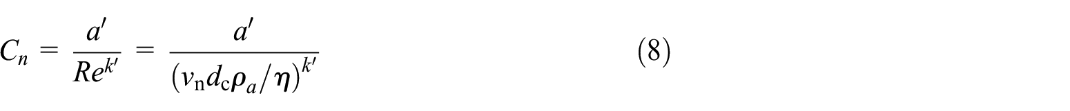
The air-phase pressure drop can be obtained directly by theoretical calculation or experimental measurement, while cuttings-phase pressure drop cannot be obtained directly. Due to the limitation of experimental conditions, it is often necessary to establish a calculation equation for the cuttings-phase pressure drop based on the obtained experimental data, which is convenient for predicting the cuttings-phase pressure drop under other working conditions. According to Darcy–Weisbach equation, 22 the cuttings-phase pressure drop can be expressed as

where
Equation (17) shows that the establishment of calculation equation for the cuttings-phase pressure drop is mainly to determine the pressure drop coefficient of the cuttings phase

According to the dimensional analysis method, equation (18) can be expressed as

where
The cuttings density

The equation (19) can be expressed as

Based on equation (21), the empirical equations of the pressure drop coefficients of cuttings phase with different particle size can be obtained after the multivariate linear regression analysis of test data.
Pressure drop coefficient of cuttings phase with fine cuttings is

Pressure drop coefficient of cuttings phase with medium cuttings is

Pressure drop coefficient of cuttings phase with coarse cuttings is

To verify the accuracy of equations (22), (23), and (24), the pressure drop coefficients of cuttings phase calculated by above equations are compared with the pressure drop coefficients of cuttings phase obtained from the test data under corresponding working conditions. The errors are shown in Figure 13.
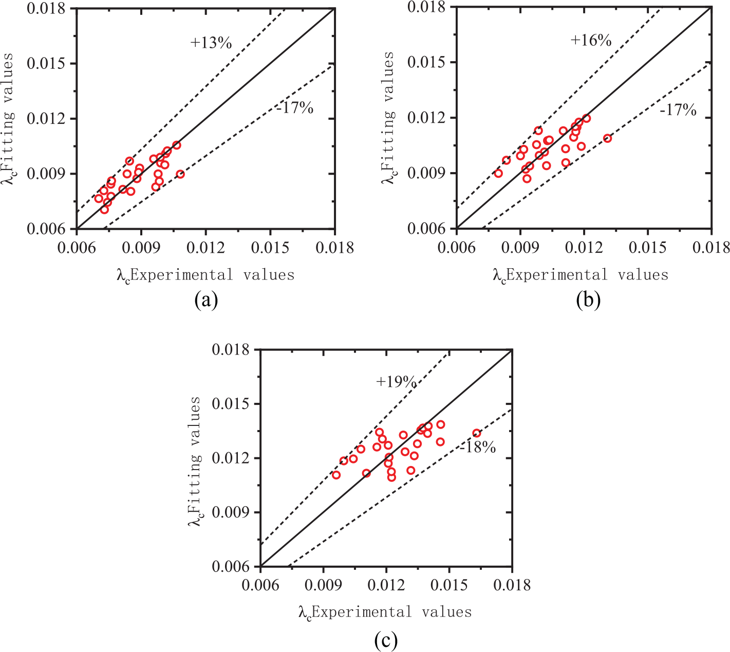
Errors between experimental values and fitting values of the cuttings-phase pressure drop coefficient. (a) Fine cuttings. (b) Medium cuttings. (c) Coarse cuttings.
As can be seen from Figure 13, the error between the test value and the fitting value of the pressure drop coefficient of cuttings phase with fine cuttings is the smallest, which is distributed between −17% and +13%. The error distribution of medium cuttings is between −17% and +16%. And the error distribution of coarse cuttings is between −18% and +19%. In a word, the coefficient errors of three kinds of cuttings are less than 20%, which shows that the empirical equation of the pressure drop coefficient of cuttings phase based on Barth’s additional pressure drop theory and dimensional analysis method can be in good agreement with the experimental values.
Conclusion
In this article, the working principle of reverse circulation pneumatic cuttings removal is analyzed and the kinetic equation of the drill cuttings in the inner hole of the drill pipe is established. A reverse circulation pneumatic cuttings removal test device is set up. The pressure drop of the drill cuttings in the inner hole of the drill pipe is measured to reveal the effects of air velocity, cuttings mass flow rate, and cuttings particle size on the pressure drop in the inner hole of the drill pipe. The results show that
The movement process of cuttings can be divided into the acceleration section and the uniform velocity section. With the increase in air velocity, the cuttings acceleration in the acceleration section and the cuttings velocity in the uniform velocity section increase. The resistance coefficient of the inner hole wall of the drill pipe and the internal diameter of the drill pipe mainly affect the cuttings velocity in the uniform velocity section. Reducing the resistance coefficient and increasing the internal diameter of the drill pipe can increase the cuttings velocity in the uniform velocity section.
The pressure in the inner hole of the drill pipe during the reverse circulation pneumatic cuttings removal is the negative pressure. The farther away from Roots vacuum pump, the smaller the negative pressure value. With the increase in air velocity, the negative pressure value and the pressure drop in the inner hole of the drill pipe increase.
In the process of cuttings removal, when the mass flow rate of cuttings is constant, with the increase in air velocity, the pressure drop in the inner hole of the drill pipe increases while the ratio of cuttings-phase pressure drop to air-phase pressure drop decreases. When the air velocity is constant, with the increase in cuttings mass flow rate, the pressure drop in the inner hole of the drill pipe and the ratio of cuttings-phase pressure drop to air-phase pressure drop increase. With the increase in air velocity, the difference between the pressure drop under different mass flow rate of cuttings increases. Under the same working conditions, the order of the pressure drop in the inner hole of the drill pipe with different particle size cuttings is as follow: coarse cuttings > medium cuttings > fine cuttings.
According to Barth’s additional pressure drop theory, the empirical equation of the cuttings-phase pressure drop coefficient is obtained by dimensional analysis and regression fitting. The errors are within 20%.
Footnotes
Declaration of conflicting interests
The author(s) declared no potential conflicts of interest with respect to the research, authorship, and/or publication of this article.
Funding
The author(s) disclosed receipt of the following financial support for the research, authorship, and/or publication of this article: This work was supported by the Natural Science Foundation of Henan Province (Grant No. 182300410156)