
Abstract
A flexible multibody dynamic calculation model based on thermo-elasto-hydrodynamic lubrication bearing model was established. This numerical simulation method provided a more realistic turbocharger calculation model and a more reliable theoretical support for studying the dynamic vibration characteristics of the floating ring bearing turbocharger system. In order to fully consider the dynamic characteristics of each component, the behavior of the floating ring bearing was described by generalized incompressible Reynolds equation in thermo-elasto-hydrodynamic lubrication model. The flexible body substructure models were established by the modal synthesis method. Based on this model, the direct mathematical model of the relationship between the eccentricity of the rotor and the oil film clearance on the turbocharger’s surface vibration was established. The influence of eccentricity and oil film thickness on the surface vibration of the turbocharger body was calculated by transient dynamics method. The results showed that the eccentricity of the rotor and the vibration of turbocharger housing were monotonic functions, but the interaction between the whirl of internal and external oil films made the mechanism of the influence of the oil film thickness on the turbocharger body’s vibration complicated. The research provided a new idea for the structural vibration and synchronous noise control of the supercharger.
Keywords
Introduction
In recent years, with increasingly serious energy and environmental issues, emission regulations have become stricter worldwide. Due to this fact, turbocharged engines have become more common because of their high volume of power output, low consumption, and low emissions. However, the better performance comes at a price because turbochargers operate at high speeds, usually hundreds of thousands of revolutions per minute, and tend to be prone to fatigue and instability. For this reason, a turbocharger rotor has to be designed carefully with respect to its dynamic properties, which could be a very interesting task due to the high nonlinearity of the turbocharger’s behavior. Figure 1 shows the assembly diagram of turbocharger rotor-floating ring bearing. The structure of the turbocharger includes a turbine disk, compressor disk, floating ring bearing, and supercharger housing. When the turbocharger operates, the dynamic performance of the rotor, the lubrication characteristics of the floating ring bearing, and the instability of the oil film will have a significant impact on the working performance of the turbocharger, and they are also the main areas of concern for turbocharger performance development.

Assembly model of turbocharger rotor-floating ring bearing.
To date, a great deal of effort has been put into investigating how to guarantee the normal operation of the turbine under high speed. Li and Rohde 1 and Li 2 presented lumped parameter models for the prediction of the stability response of a floating ring bearing, wherein the effects of imbalance and subsynchronicity on the stability of a rotor supported on floating ring bearings were studied. Wan et al. 3 investigated a new type of diesel engine exhaust turbocharger rotor. Compared with the experimental data, the results showed that the finite element (FE) method provided results that more closely matched engineering practices. Liu 4 used the FE analysis method to calculate the strength and dynamic characteristics of the rotor. FE analysis software was used to analyze the dynamic characteristics of a turbine engine, and the critical speed of the rotor system was calculated. Yu and Lv 5 studied the dynamic characteristics of the flexible rotor system, rotational speed ratio, unbalanced amount, damping ratio, and viscosity as control parameters. The numerical results of the system were presented, and the long-term state of the system was predicted by Lagrange interpolation. The numerical results of the dynamic oil film force model and the steady oil film force model were compared. The rationality of the dynamic nonlinear oil film force model was demonstrated. Analytical expressions based on the solution of the Reynolds equation were used in the study. 6 Other numerical approaches to the Reynolds equation solution are based on the FE method7,8 and the finite difference method. 9 Applications also exist based on computational fluid dynamics approaches. 10
Measurements and simulations show that rotors supported in full-floating ring bearings exhibit diverse nonlinear oscillation effects,11,12 which originate in the high nonlinearities introduced by the floating ring bearings. Rotors in full-floating ring bearings show different oil whirl and oil whip phenomena (self-excited vibrations) and reveal other interesting nonlinear effects, such as superharmonic vibrations, subharmonic vibrations, jump phenomena, and locking and synchronization effects.13–15
The important parameters of a turbocharger that could strongly influence its dynamic behavior are the clearances of the films and the eccentricity of the rotor.10,16–18 Their uncertainty is affected by manufacturing tolerances and the different temperatures of the turbocharger. Wang et al. 8 studied the effect of manufacturing tolerances for limited values of both film clearances and observed that the nonlinear response can change qualitatively with changing clearances. The stability of a turbocharger with respect to the values of bearing clearances was studied by Zhang et al. 9 Moreover, the method for the clearance identification based on the measured response was developed in Papadopoulos et al., 19 and the influences on the bearing stability were discussed. Dynamic coefficients of tilting pad bearings and the effects of clearance and preload uncertainties were investigated in Quintini et al. 20 using numerical modeling. Many authors are interested in the impact of the clearance on the contact stresses 21 or on the rotor–stator collisions and related nonlinear resonances and self-excited vibrations. 22
Based on the aforesaid remarks, this article focused on the theoretical model modeling of the vibration characteristics of the supercharger, established a multibody dynamic calculation model including rotor-bearing-supercharger shell, and calibrated the calculation model with experimental results. Based on the analysis model, the influence of the design parameters of rotor and bearing on the vibration performance of supercharger was studied. This article is organized as follows: in section “Multibody model of the turbocharger system,” a brief description of the dynamic analysis procedure of a turbocharger rotor with a floating ring bearing is given. The thermo-elasto-hydrodynamic (TEHD) lubrication and flexible dynamic theories are presented, which constitute the core of the article’s research on turbocharger dynamic behavior. Section “Simulation results and dynamic behavior analysis” is composed of the dynamic simulation results of the bearing oil film pressure, turbocharger rotor vibration, and turbocharger housing vibration, as well as the turbocharger vibration measurement. Section “Investigation of structural design parameters effects on the vibration response of the turbocharger housing” includes a detailed investigation on rotor eccentricity and the outer clearance of the floating ring bearing, which could strongly influence a turbocharger’s housing response. The conclusions are included in section “Conclusion.”
Multibody model of the turbocharger system
Reynolds equation expression
Floating ring bearings have excellent low power consumption, long service life, and compact structures, and they are now commonly used in turbochargers. Floating ring bearings are nonlinear systems—both journal and ring are driven around the bearing by hydrodynamic forces even at a constant spin speed n. In a floating ring structure, a floating ring bearing will build up an inner–outer two-layer oil film system. During operation, the lubricating oil flows through the oil holes of the floating ring into the inner layer of the oil film, and then from the ends of the floating ring outward, taking away the heat generated by friction.
The Reynolds equation of a floating ring bearing can be divided into expressions for the inner and outer layers of the film. According to the generalized incompressible Reynolds equation, the oil film floating ring bearing inner and outer layers Renault expressions can be defined as follows


where RJ, Ri, and Rk in equations (1) and (2) are the main bearing journal diameter, the floating ring inner diameter, and the floating ring outer diameter, respectively; p is the oil film pressure; h is the oil film thickness; UJ and UR are the angular velocities of the journal and floating bearing, respectively;
Oil film thickness expression
During the operation of the floating ring bearing, journal misalignment will cause the local oil film to become too thin. In addition, the journal, the floating ring, and the supercharger experience elastic deformation under the effect of oil film pressure, which leads to change of the oil film thickness in the actual work along with the load change.
Considering the journal misalignment and the elastic deformation of the floating ring and the supercharger, the oil film thickness equation is described as follows

where subscripts i and k identify the parameters of the inner oil film and outer oil film, respectively. Subscripts j and r distinguish the parameters between journal and floating ring. The bearing elastic deformation is always considered as a linear process, and under compression state, it can be described as follows

where [K] is the deformation matrix and [P] is the oil film pressure matrix.
The heat distortion of bearing surface can be described as follows

where [K] is compliance matrix, [B] is the geometry matrix, [D] is the elastic matrix, and εT is the thermal strain.
Energy equation
As oil film temperature is an important item for the oil property and oil film thickness, the energy equation considering the heat convection in three directions and heat conduction in radial direction is given as follows, 23 which solved by the finite difference method is introduced to calculate the distribution of oil film

where v, u, and w denote the velocity of the oil film, cp is the specific heat, T is the temperature of oil film, k is the heat conductivity, τa is the shear stress, and ushell, ujournal is the velocity of the contacting surface.
The heat transfer between the oil film and the bearings surface and journal has been assigned as boundary conditions for the energy equation. With the assumption that the journal temperature is constant, the heat generated within oil film flows into bearing shell continuously. The general form of the solid heat conduction equation can be expressed by equation (7), and the outer surface boundary condition can be expressed by equation (8)


where ∇ is the Laplacian operator, ρs is the density of the bearing material, cps is the specific heat, ks is the heat conductivity, and Bi is the Biot number.
Mass conserving cavitation algorithm
In this article, a mass conserving cavitation algorithm was included, which is based on the idea of Kumar and Booker. 24 This algorithm assumes that the oil film region contains liquid region and gas/vapor region. The liquid is assumed incompressible, and the gas/vapor is assumed compressible with zero bulk modulus. The density and viscosity of the biphase lubricate mixture can be described as

The relation between the density and viscosity in the biphase region is assumed to be

The oil film can be distinguished by the oil density, complete oil film region, and incomplete oil film region. The complete oil film region is filled with liquid oil
Rough contact equation
The floating ring bearing works within the hydraulic lubrication area under the action of the lubricating oil most of the time. However, the floating ring bearings may work within mixed friction areas under some special conditions, and it increases the heat, wearing, and even sintering of the bearing. Therefore, in the analysis of the bearings, the study of mixed friction is not negligible. In order to analyze the rough contact surface friction performance, the Greenwood–Tripp theory has been introduced at a mixed friction area. The rough contact surface friction pressure equation is described as follows

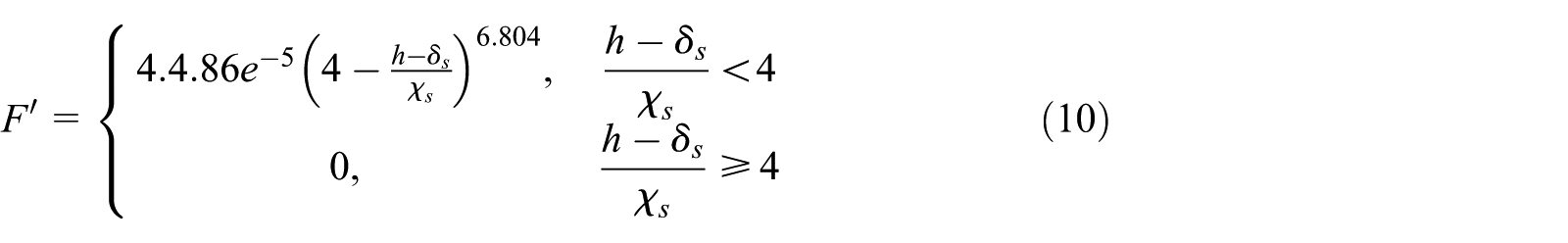
where Pa is the nominal pressure, ζ is the mean square root of the peak roughness, Rs is the rough surface peak radius, χs is the sum of the rough peaks on the contact surface, δs is the roughness, E* is the complex elastic modulus of the rough surface, and E* can be described as follows

where E1 and E2 are the elasticity moduli of the friction pair material, and v1 and v2 are Poisson’s ratios of the friction pair material.
Load equilibrium equation
The governing equations of motion for turbocharger rotor-floating ring bearing system can be formulated as

where M is the mass matrix, D is the damping matrix, K is the stiffness matrix, and Q is the displacement vector.
In general, the moment of inertia of the oil film can be ignored, so the equation of motion can be expressed by equation (13) 25

where qj is the velocity of the center of the journal, fj is the journal load, and fp is the resultant oil film force of the bearing.
Solution procedure
According to the initial conditions, equation (12) is used to solve the displacement parameters. Based on the displacement calculation results, the bearing contour and bearing clearance can be calculated by means of difference values. The viscosity and density of the oil film are determined according to the initial conditions, and the hydraulic lubrication pressure and rough contact pressure are solved by combining Reynolds equation and rough contact equation. After the pressure calculation is completed, the force at each node of the contact surface is calculated by integral algorithm; then, the force and displacement of each contact body are calculated by equation (12). Meanwhile, equation (4) is used to solve the elastic deformation of the bearing and equation (6) is used to solve the oil film density and viscosity parameters. The heat conduction calculation of bearing structure is carried out using equations (7) and (8), and the solution of hTi for bearing thermal deformation clearance is obtained by equation (5). Therefore, the new oil film thickness h can be calculated by equation (3). This process usually needs to be repeated many times until the calculation results meet the convergence conditions.
Substructure dynamics modeling of the turbocharger
The modeling and simulation process of the high-speed rotor dynamics is a rather essential task that should accompany the virtual prototype development of exhaust gas turbochargers. The turbocharger is modeled as a 3D flexible multibody system and is discretized by FEs.
FE substructure modeling is based on the modal synthesis method. The modal synthesis method is one of the important approaches to investigate the dynamic characteristics of the floating ring bearing system. 1
The basic idea of the modal synthesis method is to divide the complex structure into several substructures, the modal of which can be obtained using various discretization methods using dynamic analysis. Through the coordinate transformation, an independent generalized coordinate would be obtained, the use of which could provide a detailed description of the whole kinematic system.
The modal synthesis method can reduce degrees of freedom of the turbocharger dynamic model greatly, thereby economizing on simulation time and computational resources. The main structures of the turbocharger were meshed with second-order 10-node tetrahedron FEs. While modeling, curving of the castings and the process chamfers was ignored. Appropriate simplifications were applied to the turbocharger housing model, the FE mesh, which is composed of 270,000 nodes and 160,000 elements.
For the turbocharger rotor, a vital component in rotating machinery, it is necessary to retain the original structure details during FE meshing. In order to guarantee the dynamic simulation precision of the turbocharger’s actual operating state, a mesh refinement of the rotor is necessary. The FE mesh of the rotor is composed of 440,000 nodes and 280,000 elements. The FE models of the turbocharger housing and rotor are shown in Figure 2. Typically, several preprocessing steps of turbocharger FE modeling have to be conducted after the meshing work completed.

Finite element mesh of the turbocharger with second-order 10-node tetrahedrons: (a) FE model of the turbocharger rotor and (b) FE model of the turbocharger housing.
First, the turbocharger housing nodes are connected to the corresponding node sets on the engine body using rigid multipoint constraints, which are defined to simulate the actual interaction between the two components. Next, for the convenience of the TEHD calculation, 3-DOF of the nodes near the rotor and the floating ring bearing are retained, including five layers of nodes along the axis and 48 nodes along the circumference. Finally, the modal condensation process of the FE model should be conducted, and thus the mass matrix and the stiffness matrix used for multibody dynamic analysis can be obtained, which constitute the multibody dynamic substructure model of turbocharger.
Design parameters of turbocharger
After the substructure dynamics modeling is completed, the turbocharger assembling work should be conducted according to the actual situation. The emphasis of this article’s simulation computation, which could strongly influence the dynamic simulation accuracy, is the parameter setting of the floating ring bearing.
According to the requirement of calculation for the TEHD model, some basic parameters of the floating ring bearing, such as the structure parameters of the rotor and the impeller, the basic parameters of the lubricating oil, and other parameters are listed in Table 1. As the turbocharger substructure assembling and the floating ring bearing setting are completed, the multibody dynamic calculating model can be obtained. This model is used to simulate the actual operating performance of the turbocharger.
Main data for the rotor/bearing system.

Boundary conditions of multibody dynamics
While working, the main excitations acting on the turbocharger rotor-bearing system include the exhaust pressure pulsation, the rotor dynamic imbalanced force, and the engine exciting force.
Ying et al. 26 investigated the effect of the engine foundation’s excitation on the dynamic behavior of a turbocharger by employing a dynamic model and a numerical calculation. The result shows that the rotor dynamic behavior becomes more complicated with the foundation excitation, and the rotor will reach the chaos state at a lower rotating speed as well, compared to circumstances without foundation excitation.
Smolik et al. 27 studied the influence of bearing clearances on the dynamic response of the turbocharger rotor and suggested that the bearing clearance can generate sub-synchronous components of the rotors’ response, or at least define their magnitudes.
In this article, the effect of the imbalanced force caused by the rotor’s rotation on the rotor dynamic and the turbocharger housing’s response has been investigated. While setting boundary conditions, the rotating speed of the rotor should be defined as part of the dynamic simulating system.
In this study, the rotating speed of the turbocharger rotor is increased from 20,000 to 200,000 r min−1, and the interval is 20,000 r min−1. The dynamic model of the turbocharger is depicted in Figure 3.

Dynamic computing model of the turbocharger.
The dynamic boundaries as well as the surrounding geometric conditions of the oil film bearing system allow the consideration of certain assumptions and simplifications.
Simulation results and dynamic behavior analysis
In this section, the run-up simulations with the turbocharge model of section “Multibody model of the turbocharger system” are presented. The hydrodynamic pressure of the inner and the outer oil films as well as the vibration performance of the turbocharger rotor and the housing are studied based on the simulation result. A run-up experiment test, measuring the vibrations of the compressor-sided turbocharger housing, is carried out on the engine test rig to validate the dynamic model.
Dynamic results of oil film pressure
In this study, the bearing oil film pressure is calculated. Figure 4 depicts the comparison of the maximum inner oil film pressure of the compressor-sided floating ring bearing at different rotor speeds. As can be seen, the maximum pressure of the inner oil film changes greatly with the change of the rotor speed
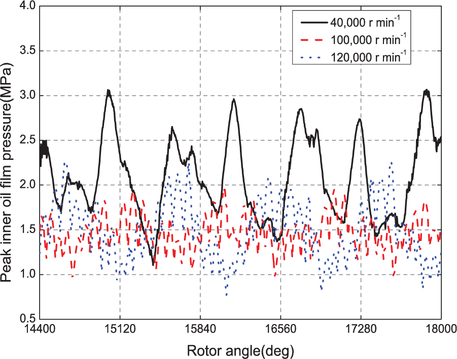
Simulation result of the inner oil film peak pressure,
When the rotor rotates at a low speed, such as
When the rotor speed
However, the outer oil film pressure of the compressor-sided floating ring bearing is only affected by the rotational speed of the floating ring.
To illustrate this fact, the comparison of the maximum outer oil film pressure at different rotor speeds is depicted in Figure 5. It is obvious that the peak pressure of the outer oil film changes a little with the variation of the turbocharger rotor speed.

Simulation result of the outer oil film peak pressure,
Analysis of rotor vibration response
Theories of rotor vibration performance
A rotor is considered unbalanced. The unbalance is realized by the shifting centers of mass of the impellers in the radial direction. Owing to this factor, there will be significant vibration phenomena when the turbocharger operates.
The vibration caused by unbalanced rotor will always be consistent with the rotor’s first-order vibration frequency, so it is described as a synchronous vibration. The synchronous frequency can be solved by equation (14)

where
Furthermore, when the floating ring bearings rotate at a high speed, the forced synchronous vibration is accompanied by an oil whirl. An oil whirl is a kind of self-excited vibration caused by fluid dynamic forces generated in the oil-lubricated bearings. The oil whirl will cause the instability of the rotor and may sometimes be disadvantageous in terms of noise and vibration generation.
In turbochargers with floating ring bearings, there exist two parts of the oil whirl, the inner oil whirl and the outer oil whirl.
The inner and outer oil whirl frequencies can be generally expressed as equations (15) and (16). As can be seen, the ratio of the frequency of the oil whirl to the rotational speed of the rotor is a constant, and generally, it is 1/2. Therefore, it is defined as a subsynchronous vibration


where
Analysis of the simulation result
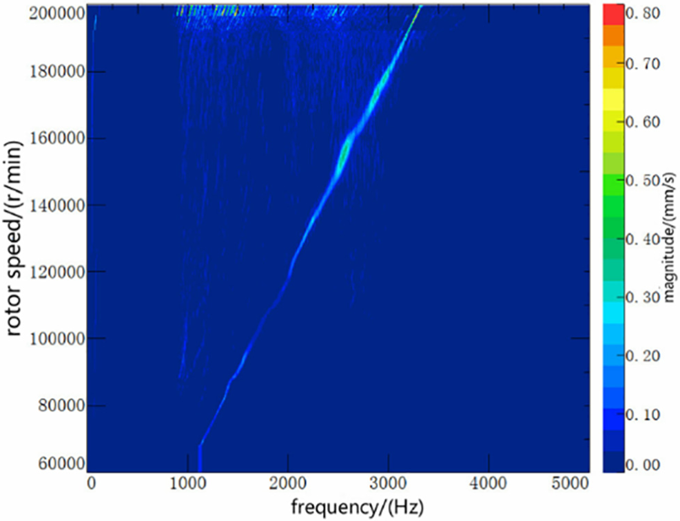
To express the vibration performance of the compressor-sided rotor, the amplitude of the vibration velocity has been used in the spectrum depicted in Figure 6.

Run-up spectrum of the vibration velocity of the compressor-sided rotor.
The spectrum cascade can be subdivided into four characteristic sections:
(a) Range 1:
Note that there exist vibrations of significant order in this rotor speed range and the corresponding frequency
When
When
(b) Range 2:
The corresponding frequency is
The subsynchronous vibration nearly disappears, and the main component of the rotor’s vibration is the first-order synchronous vibration caused by the rotor’s eccentricity.
(c) Range 3:
The subsynchronicity caused by the inner and outer oil whirls and the synchronicity caused by the rotor eccentricity occur simultaneously, and the corresponding frequency is
(d) Range 4:
When
The spectrum of the vibration velocity of the turbine-sided rotor at a run-up simulation speed in Figure 7. It can be seen that the vibration response of the turbine-sided rotor is similar to that of the compressor-sided rotor:
When
When
When
When

Run-up spectrum of the vibration velocity of the turbine-sided rotor.
Dynamic result of the turbocharger housing
Since the hydrodynamic bearings that support the rotor are set in the center of the turbocharger housing, the effect of the turbocharger housing vibrations should be considered and treated as the foundation excitation for the turbocharger rotor dynamics. The vibration response of the turbocharger housing can also be obtained from the multibody dynamic simulation. The simulation results of a point on the compressor-sided turbocharger housing were extracted to gain further insight into the turbocharger dynamics.
Furthermore, the position of the extracted point should be convenient for the arrangement of the sensor, in order to develop the test to validate the accuracy of the dynamic simulation results.
The normal vibration velocity of the extracted point at the compressor-sided housing is used in the spectrum depicted in Figure 8.

Test result of the normal vibration velocity of a specific point on the turbocharger housing.
It can be seen that the synchronicity caused by the rotor eccentricity occupies a large proportion of the housing vibrations, while the subsynchronicity caused by the oil whirl is not significant. In other words, synchronous vibration is the main vibration form of the turbocharger housing.
It is obvious that there is a high peak of vibration amplitude at a rotor speed between 60,000 and 100,000 r min−1, the center speed of which is 80,000 r min−1. It indicates that the synchronous vibration of the turbocharger housing occurs due to the excitation of the rotor vibrations.
When
When
Experimental test of the housing vibration response
A run-up measurement, carried out on an engine test rig to measure the vibration response of a specific point on the compressor-sided turbocharger housing, is presented and discussed in this section. The position of the measurement point is depicted in Figure 9. An LMS 48 channel test front-end and a PCB triaxis accelerometer are used in the surface vibration test of supercharger. The effective measurement frequency range of the test is 0–6400 Hz, and the range of the accelerometer is 0–100 g.

Arrangement of the measurement point on the turbocharger housing: (a) vibration test diagram and (b) measuring point position.
Three-direction vibration velocities of the specific point were measured in a run-up engine speed range of 1000–6000 r min−1 in a semianechoic room.
Furthermore, the vibration response of the vertical and horizontal directions of the measurement point should be stressed, so the measurement result of vertical direction was extracted and made into a waterfall plot, as depicted in Figure 10.
Under engine full load conditions, the turbocharger would get involved in operating at an engine speed of 1500 r min−1. The corresponding turbocharger speed is 84,000 r min−1, and the synchronous frequency is 1400 Hz. As the engine speed continually increases, the turbocharger operating speed would gradually increase to 200,000 r min−1, and the synchronous frequency would gradually reach 3300 Hz.
As can be shown from test the result, when
When
While at
Waterfall plot for the normal vibration velocity of an extracted point on the turbocharger housing.
Compared with the run-up simulation result in Figure 10, the vibration response of the turbocharger housing obtained from the test results keeps a high consistency with the simulation results at a low rotor speed range of
According to the engine calibration strategy, the supercharger speed range studied in this article is between 120,000 and 200,000 r min−1. Table 2 shows the comparison between the measured value and the calculated value of supercharger’s surface vibration velocity at common working speed. From the comparison results, the ratio between the experimental value and the calculated value of supercharger surface is about 0.35 under various working conditions, which indicates that the flexible multibody dynamic calculation model established in this article maintains good stability and reliability, and the calculation results of this model have a guiding significance for the study of the vibration characteristics of supercharger.
Comparison of test and calculated values of supercharger vibration velocity.

Meanwhile, it can be seen from the comparison of the simulation result and the test result that there is still some deviation, mainly because of the following:
The measurement was conducted on the test rig, and the actual operating state of the turbocharger would be different from that in the dynamic model. There are still some improvements in the dynamic model, including the boundaries of the floating ring bearing and the modeling of the turbocharger rotor and the turbocharger housing.
Investigation of structural design parameters effects on the vibration response of the turbocharger housing
The experimental test method is commonly used to research the vibration response of turbochargers, although it has the disadvantages of a long period and high cost. In this article, the multibody dynamic simulation method adopted can investigate the turbocharger operating performance in more detail and the work efficiency is conveniently improved as well.
A vibration system of the turbocharger mainly includes the engine’s foundation excitations, synchronous vibration due to rotor eccentricity, and subsynchronicity caused by the oil whirl and high pulsating turbine pressures.
Moreover, the engine’s foundation excitation has maximal vibration energy, and the vibration frequency range is always less than 1000 Hz. The energy of synchronicity takes second place in the frequency range above 2000 Hz. The subsynchronicity often mixes with the engine’s excitation in the speed range below 2000 Hz. The vibration energy generated by high pulsating turbine pressures is relatively low, which would not be demonstrated in this article.
The vibration response of synchronicity differs greatly from that of the engine’s body, and the associated noise phenomena are rather serious, which could cause driver discomfort. Under the circumstances, the investigated emphasis should be concentrated on the synchronous vibration response; for instance, the effect of different design parameters on turbocharger synchronous is discussed in this section.
Figure 11 depicts the vibration velocity comparison of the measurement point on a turbocharger housing under different rotor eccentricities. As can be seen:

Comparison of the turbocharger vibration response when the rotor eccentricity is 0.5, 1, 1.5, and 2.0 mm.
At the rotor speed of 18,000 r min−1, synchronicity is the dominant vibration form of the turbocharger housing, subsynchronicity due to the outer oil whirl takes the second place, and the influence of inner oil whirl on the turbocharger vibration is minimal;
Moreover, the synchronous and subsynchronous vibration responses become more significant with the increase of the rotor eccentricity, which corresponds to the turbocharger’s actual operating circumstances. However, due to the limitations of machining accuracy and manufacturing cost, it is impossible to reduce rotor eccentricity infinitely and it is acceptable to control it within a reasonable range.
The vibration performance of the turbocharger housing is also affected by the outer clearance of the floating ring bearing, the effect of which is depicted in Figure 12 to illustrate the comparison results (inner bearing clearance is comparatively small and limited by design space).

Comparison of the turbocharger vibration response when the outer bearing clearance values are 0.03, 0.025, 0.02, and 0.015 mm.
The outer clearance may not affect the turbocharger synchronous vibration; it may have a significant influence on the turbocharger’s subsynchronous vibration. When the outer bearing clearance is 0.03 mm, the outer oil whirl is very obvious and causes a sharp increasing of the vibration amplitude of the subsynchronicity at 400 Hz.
The subsynchronous vibration amplitude of the turbocharger gradually decreases with the reduction of the outer bearing clearance, but when the outer bearing clearance drops to a certain level, the subsynchronous vibration amplitude caused by the outer oil whirl will tend to be stable.
When the outer clearance is reduced to 0.015 mm, there is an obvious amplitude peak at a frequency around 1550 Hz, and it can be deduced to be the inner oil whirl frequency of the floating ring bearing from equation (14).
The studies indicate that the outer clearance of the floating ring bearing has a significant effect on the turbocharger’s subsynchronicity, and reasonable design parameters for the bearing clearance could greatly reduce the subsynchronicity of the turbocharger.
Conclusion
A flexible multibody dynamic model with TEHD bearing of high-speed gasoline engine turbocharger was established. Based on this model, the mathematical model of vibration transmission path for rotor dynamics—floating ring bearing—turbocharger body was established. The comparison between the surface vibration acceleration of the supercharger body and the calculated results showed that the mathematical model worked very well. The calculated results kept a high consistency in trend over the whole speed range with experimental test results in the frequency-amplitude variation.
The relationship between rotor eccentricity and turbocharger synchronous vibration was inversely proportional. With the increase of rotor eccentricity, the amplitudes of the synchronous and subsynchronous vibrations of the turbocharger increase gradually. Therefore, reducing rotor eccentricity was an effective measure to control the synchronous vibration of the turbocharger body.
Bearing clearance has a great influence on the subsynchronous vibration of the supercharger, and the mechanism is more complicated. For example, at 180,000 r min−1, when the outer bearing clearance is 0.03 mm, the outer oil film whirling phenomenon causes obvious subsynchronous vibration of the supercharger body at 400 Hz. However, when the outer oil film clearance is 0.015 mm, the 400 Hz subsynchronous vibration peak was obviously reduced; but a 1550 Hz subsynchronous vibration peak appeared because of the enhancement of the inner oil film whirling phenomenon.
This article shows that it is necessary and effective to establish the multibody dynamic model of rotor-floating ring bearing-supercharger body for studying the synchronization and subsynchronization phenomena of the supercharger. This method will provide a more reliable theoretical support for vibration and structural radiated noise control of supercharger.
Footnotes
Declaration of conflicting interests
The author(s) declared no potential conflicts of interest with respect to the research, authorship, and/or publication of this article.
Funding
The author(s) received no financial support for the research, authorship, and/or publication of this article.