
Abstract
In this article, the disk mill cutter path generation strategy for the machining of complex helical surface via a currently developed minimal orientation-distance algorithm based on spatial discretization method is studied. The strategy proposed here is, first, to establish the helical surface and cutting surface in the unique coordinate system. Then, the two surfaces are divided into a series of parts by n equidistant planes, and the minimal orientation-distance algorithm is used to determine all the cutter locations. Finally, on the basis of Archimedes helical interpolation, cutter path is generated within the specified tolerance limit. The effectiveness of the proposed strategy is confirmed numerically and experimentally by a case of virtual cutting test in VERICUT software and actual machining. This strategy can be applied to a broad range of helical surface machining.
Introduction
Positive displacement motor (PDM) is a main kind of powerful downhole drill motor in oil and gas industry, especially in horizontal wells and lateral wells. 1 Leakage and torque losses play an important role in the performance of a motor. These losses decrease the effects significantly. As a vital part of PDM, the machining quality of screw rotor directly affects the working performance and life. Form milling and envelope milling are the main two types of techniques for screw motor machining. Form milling2,3 is a technique in which the form cutter moves along the given curves and produces the helical surface. Because of tool wear, cutter uniqueness to a specific screw rotor, the machining is time-consuming; also, undercutting and interference often occur. However, envelope milling is a powerful machining method, in which the main concern is to find the precise locations of the tools. Since 1980s, the tool path generation has been addressed by a number of researchers. Generally, for tool path generation, the cutter contact paths are usually first generated on the design surface, and then the cutter reference point can be determined by the cutter contact point, normal vector, and cutter shape. However, this method involves complicated mathematics and requires that the profiles be continuous. The profile of the PDM screw rotor is complex. Therefore, some types of techniques for tool path generation4,5 were proposed:
The APT-based tool path method.6,7 The tool paths are defined along the intersection curves between the desired surface and drive surfaces. At each step, numerical iteration searches are made to locate the cutter position with a specified tolerance limit. The disadvantages of this method are that the iteration searches are time-consuming and may be not converged for the complex helical surface.
The Cartesian machining method.8–10 The tool paths are generated by referring to the workpiece space only. In general, a pre-processing step transfers the initial surface to a set of simpler entities, usually points or curves of intersection, given by intersecting the surface (or its simpler presentation) by parallel planes. Afterward, the cross sections obtained can be considered as independent from the parametric space of the original surface.
Parametric machining method. The tool paths are generated on the parametric space. Afterward, the results are mapped onto the surface space. Five subcategories of parametric machining can be distinguished.8,11
The existing studies show the following issues of tool path generation: time-consuming, converge uncertainty, and complicated mathematics. Spatial discretization method is an available method to overcome the problems. Based on the issues, in screw rotor machining, focus should be placed on the spatial discretization strategy, interpolation method, and the error control. As discussed above, a new strategy of minimal orientation-distance algorithm with spatial discretization method is proposed to generate the tool path. The minimal orientation-distance (MOD) method is widely used to find the engaging point between two smooth surfaces.12,13 On principle of MOD, the problem of achieving instantaneous engaging point is transformed into least-value problem of corresponding points between work piece surface and tool surface. Spatial discretization method is used to solve these points. On the basis of Archimedes interpolation curve, the cutter path is generated between two cutter locations within the tolerance limit. Meanwhile, the numerical control (NC) code is produced according to the numerical algorithm automatically. Virtual machining of screw rotor is conducted in VERICUT software. Finally, the validation of the proposed tool path generation strategy is demonstrated by the actual cutting test.
This article aims at providing a new method to form a complex helical surface. The major difference of the proposed method from analytical method as well as other computer simulation methods is that the proposed method is more precise and efficient, which is established on the basis of MOD algorithm with discretization method. This article will be organized as follows. In section “The MOD method,” the MOD method is introduced to calculate the profile of disk mill cutter. Meanwhile, a virtual machining method is applied to machining helical surface in section “Virtual machining of screw rotor.” Then, the proposed method is validated experimentally on the basis of helical surface machining in section “Actual cutting test of screw rotor.” Finally, we summarize the main results and present the conclusion in section “Conclusion.”
The MOD method
Definition of MOD
If two surfaces are all-smooth surfaces (continuation and first-order differentiable), a pair of MOD points along the final motion (excluding boundary points) are a pair of contact points on two surfaces in engaging movement when interference does not exist.
Solving MOD using spatial discretization method
As shown in Figure 1, to solve the minimal distance between surface S1 and surface S2 at x-axial direction, these two surfaces are divided into


Schematic representation of spatial dispersing curved surface (a) the surfaces divided by a series of planes and (b) is the projection of cross-section profile Plane Pk.
Mathematical model of helical surface and disk mill cutter
Modeling of helical surface and disk mill cutter
According to the forming principle of helical surface, the screw rotor surface can be considered as the helical motion of the transverse profile along the helix (as shown in Figure 2(a)). The equation of transverse profile and helical surface are expressed as equations (2) and (3)

where r is the radius vector of the transverse profile; u is the shape parameter of transverse profile; i and j are the unit vectors along x-axial and y-axial directions, respectively.

where x, y, and z are the coordinate values of the spatial helical surface in oxyz coordinate system, respectively (mm);

(a) Helical surface of the screw rotor and (b) cutting surface of the disk mill cutter.
The cutting surface (shown in Figure 2(b)) is formed by the nose part rotating around the central line of the cutter. The cross section and the cutting surface are shown in Figure 3 and the cutting arc can be given as follows

where R is the distance from a point on the nose to the rotation center,
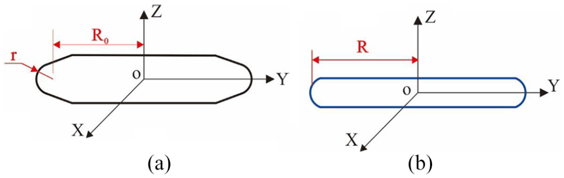
(a) Cross section and (b) cutting arc of the disk mill cutter.
Coordinate transformation
To study the envelope profile, the coordinate systems and the relative position of the screw rotor and the disk mill cutter are established, as shown in Figure 4, in which oxyz is the screw rotor coordinate system and OXYZ is the disk mill cutter coordinate system. The rotation of the workpiece around z-axis can be expressed by rotation matrix

where

Position relationship between the helical surface and the disk mill cutter.
In numerical simulation, the coordinate systems should be unique. In this article, the cutter coordinate system is regarded as the main coordinate system. Therefore, the helical surface coordinate system is transformed into the cutter coordinate system through a coordinate transformation matrix, which can be defined as follows

where d is the distance between the two central axes of the helical surface and cutting surface, mm; B is the rotation angle of the screw rotor around x-axis (as shown in Figure 6), and the magnitude is equal to the complementary angle of the spiral angle (rad).
The magnitude of d can be picked arbitrarily on the condition that the two surfaces are not interference. After the coordinate transform operation, the helical surface and cutting surface have the consistent coordinate system. The process of transformation has the following expression

where
Principle and algorithm of cutter path
To generate the cutter path of a helical surface, the MOD algorithm is established using spatial discretization method. The flowchart for the cutter path generation strategy is shown in Figure 5 and the loop program can be employed to understand the envelope process.

The flowchart of tool path generation for helical surface.
Principle of MOD envelope
In this section, the spatial discretization method is used to calculate the MOD. As shown in Figure 6, the height of the cutter is two times of h at Z-axial direction. The cutting surface and helical surface are dispersed by a series of equidistant planes which is perpendicular to Z-axis.

Spatial dispersion of the helical surface and cutting surface.
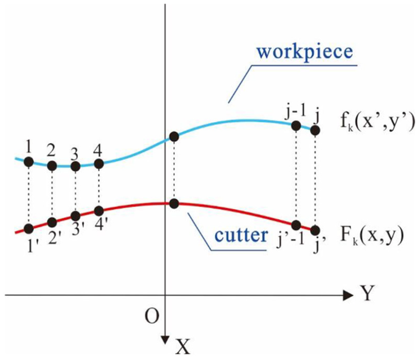
Planar dispersion of the helical profile and cutter profile.
In addition, the profiles are dispersed on each plane by the equidistance line which is vertical to Y-axis. After the spatial and planar dispersion, a series of discrete points are obtained on the profiles as shown in Figure 7, denoted as

where

Algorithm of cutter path
To simplify the simulation, half cutter path is studied in the following simulation based on the symmetry of screw rotor profile. The angle between the major diameter and the minor diameter of helical surface profile is dispersed with the step size
In the actual machining, the relative position of the helical surface and disk mill cutter is shown in Figure 4. When the cutter envelopes a circle of the screw rotor, cutter location is variable just in the X-axial direction.
The time of one circle cutting is divided into n time steps. According to the envelope-milling theory, the displacement of cutter in x-axial direction is equal to MOD between two surfaces. At every time step, the initial location of the cutter keeps the same, denoted as

To determine the interpolation nodes used to the NC code, the obtained cutter locations are interpolated on the basis of Archimedes helical interpolation. The interpolation step size is decided by the specified tolerance limit between the cutter envelope profile and the theoretical profile. The process is presented in Figure 8, where

The sketch of Archimedes helix interpolation theory.
In the envelope process of the helical surface with pitch diameter, iterative interpolation calculation is taken around z-axis of the screw rotor in an anticlockwise direction along the Archimedes helix (shown in Figure 8). The number of starting point and the ending point are, respectively, marked with Q and E, and

where
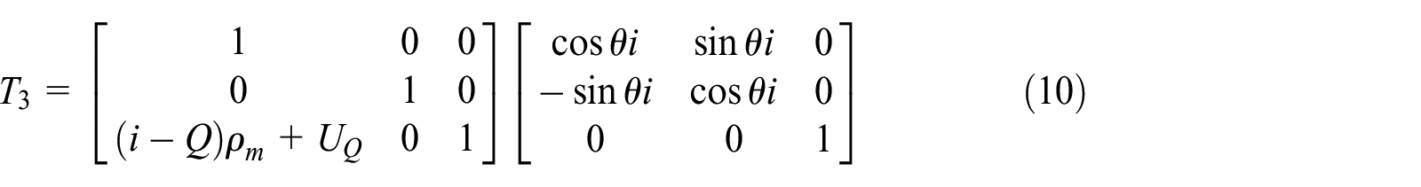
Archimedes helical movement of the cross section can be derived by matrix T3
where
The interpolation nodes set S is obtained, and the polar coordinate is

where X and C are the values of the X-axis coordinate and the C-axis coordinate in the NC program, respectively.
A case of simulation
A numerical example is conducted on envelope milling using of left-handed screw rotor. The theoretical profile of the screw rotor is shown in Figure 9, and the theoretical profile data are as follows:

The envelope process on the middle cross section of the cutter.
The lead of the rotor is 1000 mm. The cutting parameters include cutter plate radius 140 mm, tool nose angle


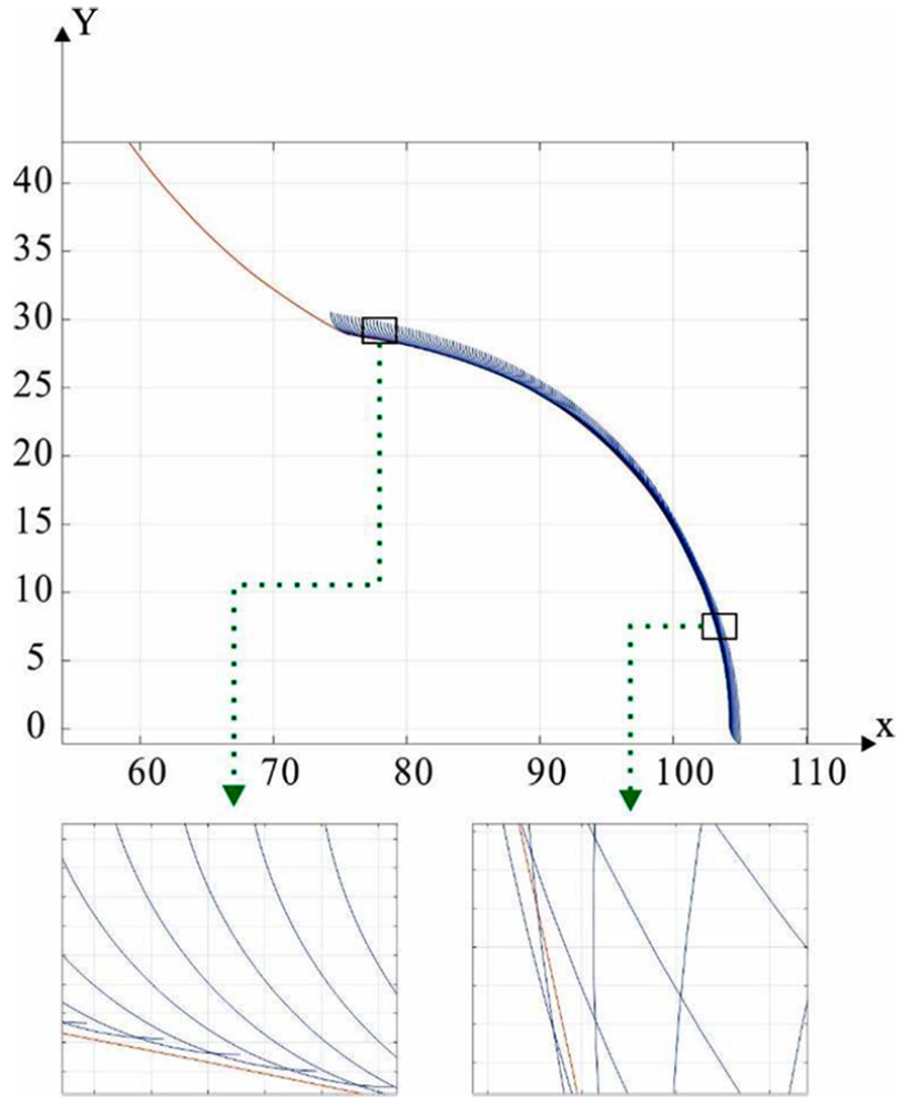
The theoretical profile and simulation profile.
Theory and simulation profiles are shown in Figure 10, and the error distribution of the simulation results is presented in Figure 11. Although undercut and overcut still exist, the range of the error is within the tolerance limit 0.05 mm and the largest error is around

The error distribution between the simulation profile and the theoretical profile.
Virtual machining of screw rotor
In order to test the NC code and the cutter path generation strategy, virtual machining environment for the envelope milling is developed in the VERICUT software, which can simulate the machining process. First, the geometric model of the machine is necessary to build the virtual environment. Then, the machine kinematics is analyzed to get the follow-up relationship of the machine axes. Finally, the moving structure is constructed, and the kinematics model of the tool and the workpiece is established. In addition, the control system is needed to be customized according to the general NC code. Figure 12 shows the cutting process in VERICUT software.

The virtual machining process in the VERICUT software.
The machining simulation can check the undercutting, collision, and interference between the workpiece and disk mill cutter. Meanwhile, the machining quality of the screw rotor is checked by the theoretical screw rotor model. The result of the error distribution on the screw rotor surface is shown in Figure 13. The red area represents the worst quality, which means the polar radius is larger than the theoretical rotor. Compared with the numerical simulation error, it almost has the same error distribution. Therefore, the virtual machining model is available to simulate helical surface machining.

The error distribution using virtual machining method.
According to the error distribution, the machining parameters, such as the cutter nose angle and the interpolation step size, can be optimized. It is useful to improve the machining precision and efficiency. Also, the worker can grind the surface of the poor-quality area.
Actual cutting test of screw rotor
The generated NC code in VERICUT software is applied to machining a sample of screw rotor in CNC machining center. Figure 14 shows the product. The profile of the screw rotor is measured by the trilinear coordinates measuring instrument. Machining profile is shown in Figure 15. As illustrated in Figure 16, the error magnitude almost has the same range with the simulation error, and the peak of the error curve is around
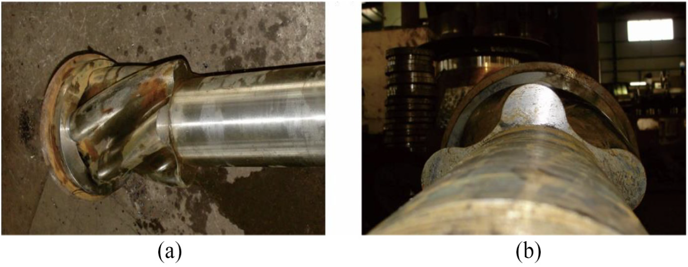
The screw rotor machined using the generated NC code, (a) is front view and (b) is top view.

Actual machining profile and theoretical profile.

The error distribution of actual cutting test.
Conclusion
Aiming at manufacturing the helical surface in high precision and efficient, this article proposed a new strategy to calculate the cutter path based on the MOD algorithm with spatial discretization method. The main conclusions are summarized as follows:
The transverse profile of the helical surface is dispersed by a series of planes, and the MOD algorithm is applied to obtain the engaging point between the workpiece and the disk mill cutter. The MOD envelope method is proposed to determine the cutter locations. The milling envelope profile is obtained on the basis of Archimedes helical interpolation curves.
The virtual machining environment is established in VERICUT software, where the error distribution, the interference, and the collision can be checked in comparison with the theoretical 3D model. Meanwhile, the generated NC code is applied to the actual machining and the result shows that the NC code is available to the helical surface machining.
The proposed cutter path generation strategy is validated by the machining of an example in virtual machining environment and actual machining in CNC machining center. The machining precision is coincident with the specified tolerance limit. With the application of proposed strategy, the machining precision and efficient will be improved.
Footnotes
Declaration of conflicting interests
The author(s) declared no potential conflicts of interest with respect to the research, authorship, and/or publication of this article.
Funding
The author(s) disclosed receipt of the following financial support for the research, authorship, and/or publication of this article: This work has been supported by the National Science and Technology Major Project (No. 2016ZX05038-005-LH001) and Grant of Key Laboratory of Oil and Gas Equipment, Ministry of Education (grant no. OGE201702-17). W.L. would like to acknowledge the financial support from the China Scholarship Council (award no. 201708510133) for his 1-year visiting study at the University of Exeter.