
Abstract
Parallel kinematic machines have been applied in aerospace and automotive manufacturing due to their potentials in high speed and high accuracy. However, there exists coupling in parallel kinematic machines, which makes dynamic analysis, rigidity enhancement, and control very complicated. In this article, coupling characteristics of a 5-degree-of-freedom (5-dof) hybrid manipulator are analyzed based on a local index and a global index. First, velocity analysis as well as acceleration analysis of the robot is conducted to provide essential information for dynamic modeling. Then the dynamic model is built based on the principle of virtual work. Whereas the mass matrix is off-diagonal, a local coupling index as well as a global index is defined, based on which coupling characteristics of the robot are analyzed. Results show that distributions of coupling indices are symmetric due to its structural features. And dimensional parameters, structural parameters, as well as mass parameters have a large influence on the system’s coupling characteristics. Research conducted in the article is of great help in optimal design and control. Meanwhile, the method proposed in the article can be applied to other types of parallel kinematic machines or hybrid manipulators.
Introduction
Parallel kinematic machines (PKMs) have received significant attention both in terms of theoretical research and practical applications due to their merits of high loads, high accuracy, and high speed when compared with serial kinematic machines (SKMs). The typical success can be verified by the application of the Tricept and Sprint Z3 in assembly and milling in aerospace and automotive industry.1–4 As is known, PKMs have large stiffness and large loading capability due to their closed-loop structural features. However, it is the closed-loop structural features that make limbs of a PKM coupled, which makes it very complicated for topological synthesis, dimensional design, performance enhancement, and control system design. Limbs of PKMs are coupled, which demonstrates that the driving force/torque of one certain limb is related to other limbs. Despite that there are many references focusing on kinematic analysis,5–7 stiffness modeling,8–10 dynamic analysis,11–13 and calibration14–16 of PKMs, references about coupling analysis are very scarce. As far as the authors are concerned, coupling analysis of PKMs involves two basic issues, one is how to establish a coupling model, and the other is how to quantify coupling strength.
In general, the dynamic model of a PKM is a highly nonlinear complex system with multiple inputs/outputs, which can be regarded as the basis of coupling analysis. There are mainly several methods of dynamic modeling, that is, Lagrange method,17,18 Newton-Euler method,19,20 Kane’s method,21,22 the principle of virtual work.23,24 The Lagrange method is based on the system’s energy. Bonnemains et al.
25
built a dynamic model of Tripteor X7, based on which inertia parameters were indentified. The Newton-Euler method describes inertia parameters, force, and acceleration of a PKM by establishing one Newton equation and one Euler equation of each part. Based on the Newton-Euler method, Wang et al.
26
proposed a simplified dynamic model which was used to the optimal design of the driving force. Relatively speaking, the Kane’s method is complicated, which calculates the generalized driving force and generalized inertia force of a system by defining partial velocity and partial angular velocity. The principle of virtual work is the most commonly used method due to its easy principle. Kalani et al.
27
presented an improved dynamic model of a 6-U
According to discussions above, this article deals with the coupling strength of a 5-dof hybrid manipulator. The remainder of the article is organized as follows. Kinematic analysis is described in Section 2, which can provide essential information for the following dynamic modeling. Based on the principle of virtual work, the rigid dynamic model is established in Section 3. Then a local coupling index and a global index are proposed, based on which coupling characteristics are analyzed in Section 4. Finally, main conclusions are drawn in Section 5.
Description of mechanical structures and inverse kinematic analysis
Figure 1 shows a 3D model of the Trimule robot proposed in Dong et al.,
10
which contains a PKM module and a 2R module. In general, the PKM module is composed of one base, one platform, three active universal–prismatic–spherical (U
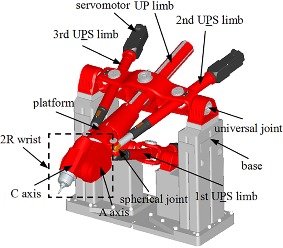
A CAD model of the Trimule robot.

Assemblage of active and passive limbs.
In order to facilitate derivation, the schematic diagram of the hybrid manipulator and several coordinate systems are depicted in Figure 3. Herein, C is the end point of the machine tool. A denotes the intersection point of A axis and C axis. Ai (i = 1 to 3) denotes the geometrical center of the ith spherical joint. A4 is the connection point on the interface of the platform and the passive limb. Bk (k = 1 to 4) denotes the geometrical center of the kth universal joint. Ck (k = 1 to 4) is the end point of the kth limb. The machine tool body-fixed frame C-xCyCzC is attached to the end point of the tool C, with the xC axis parallel to the C axis’s rotation axis, the zC axis parallel to the machine tool’s axis, and the yC axis can be decided by the right-hand rule. The A axis body-fixed frame A-xAyAzA is built at the point A, where the xA axis parallel to the C axis’s rotation axis, the zA axis parallel to the axis of the A axis, and the yA axis can be decided by the right-hand rule. B4-xyz is the global frame attached to the point B4, where the x axis points from B4 to B2 and the y axis is vertically up to B3B2. Then direction of the z axis can be determined by the right-hand rule. The platform body-fixed frame P-uvw is set at the midpoint of A3A2, with the u axis parallel to A3A2 and the w axis vertical to the platform. Accordingly, the v axis can be decided by the right-hand rule. The limb body-fixed frame Bk-xkykzk is set at the point Bk, where the zk axis is along the kth limb, the yk axis is along one rotation axis of the kth universal joint, and the xk axis can be determined by the right-hand rule. To be specific, B1 – x1y1z1 in the 1st U
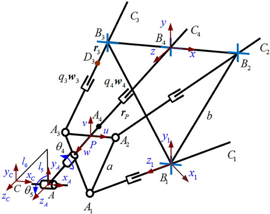
Schematic diagram of the PKM module.
Assume that the transformation matrix of the platform body-fixed frame P-uvw with respect to the global frame B4-xyz can be defined as

Similarly, transformation matrices of frames Bk-xkykzk and C-xCyCzC with respect to the global frame B4-xyz can be expressed, respectively, as


For content limitation, detailed inverse kinematics is not described in the article. Since there is no coupling in the 2R module, the following will focus on kinematic and dynamic modeling of the PKM module.
Velocity analysis
Position of the point P


where
Taking derivation of equations (4) and (5) yields


where
Taking inner dot of equation (6) by

Taking inner dot of equation (7) by


It is noted that the rotation matrix

Taking inner dot of equation (11) by

Equations (8)–(10) and (12) can be written in a matrix form as follows

where


Taking cross product of equation (6) by

where
Supposing that the mass center of the ith U

where
Substituting equation (16) into equation (17), the velocity of Di can be calculated by

where
Combining equations (16) with (18), the velocity of the mass center Di and the angular velocity of the ith U

where
Similarly, define

Thus, the velocity of the mass center D4 and angular velocity of the UP limb can be written as

where
Acceleration analysis
Taking inner dot of equation (7) by

Taking derivation of equation (13) yields

where
Taking derivation of equation (19) yields

where


Similarly, taking derivation of equation (21) yields

where
Formulation of rigid dynamics
In this section, the principle of virtual work is applied to formulate the rigid dynamic model of the PKM module. And the 2R module will be treated as the platform’s load whose inertia matrix is position-dependent. In order to facilitate derivation, the force diagram of the PKM module is depicted in Figure 4.
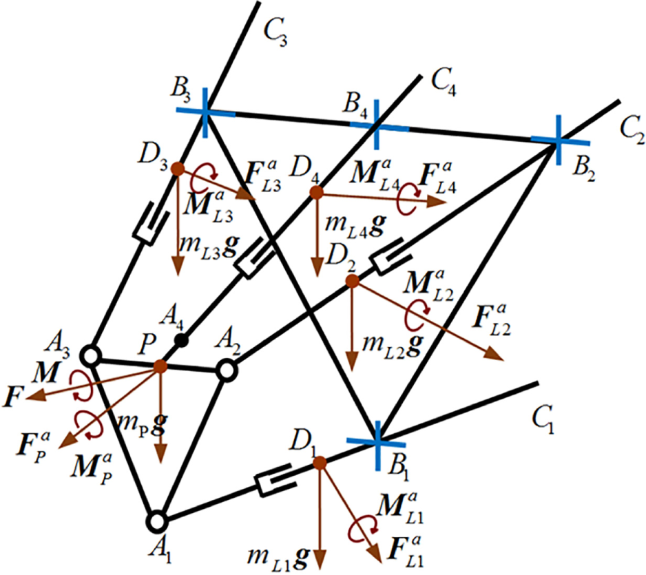
Force diagram of the PKM module.
Virtual work conducted by the platform
Assume that the external load

The inertial force and moment of the platform can be expressed as

where mP and

where mP0, mA, and mC are the mass of the platform itself, the A axis, and the C axis, respectively;
Then the virtual work conducted by the platform’s inertial force and moment can be expressed as

Substituting equation (31) into equation (33) yields

where
The virtual work conducted by the platform’s gravity can be expressed as

where
Virtual work conducted by the ith UP S limb
Assume that the external force fi (actually caused by the driving torque) is applied at the ith U

The inertial force and moment of the ith U

where mLi and
Then the virtual work conducted by the ith U

Substituting equation (37) into equation (38) yields

The virtual work conducted by the ith U

Virtual work conducted by the UP limb
The inertial force and moment of the UP limb can be expressed as

where mL4 and
Then the virtual work conducted by the UP limb’s inertial force and moment can be expressed as

Substituting equation (41) into equation (42) yields

The virtual work conducted by the UP limb’s gravity can be expressed as

Dynamic equation of the PKM module
Based on the principle of virtual work, there exists

Substituting equations (13), (19), (21), (23), (26), (29), (30), (34)–(36), (39), (40), (43) and (44) into equation (45) yields

where


where
If the generalized Jacobian matrix

where


Coupling analysis
In general, the driving force caused by

In order to extract the three driving force of the three U

where
It is noted that the mass matrix

If the PKM is not coupling, off-diagonal elements should be zero. Therefore, κi can be regarded as the local coupling index, which can be expressed as
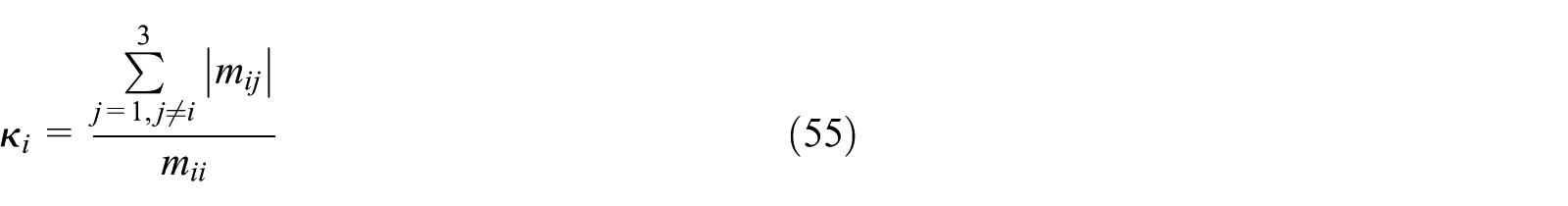
It can be seen from equation (55) that the larger the local coupling index κi is, the more coupled the system is.
Parameters of the hybrid manipulator
Main geometrical parameters and mass parameters are listed in Tables 1 and 2, respectively. It is noted that inertia of all parts listed in Table 2 is measured about their mass centers in their body-fixed frames.
Geometrical parameters of the Trimule robot.

Mass parameters of the Trimule.

Coupling analysis at a typical configuration
Taking a typical configuration as an example, where x = y = 0 m, z = 1.35 m, α = 90°, β = 0°, the calculated mass matrix is shown in equation (56). Herein, α and β are Euler angles of the machine tool fame C-xCyCzC with respect to the global frame B4-xyz.

As can be seen obviously, the mass matrix is not diagonal. Based on equation (55), three local coupling indices are calculated, that is, κ1 = 0.9578, κ2 = κ3 = 0.9145. It can be found that κ1 is larger than κ2 and κ3, demonstrating that the 1st U
Distributions of local coupling indices over a working plane
Distributions of three local coupling indices over the working plane of z = 1.35 m are demonstrated in Figure 5. Herein, both of x and y vary from −0.2 m to 0.2 m.

Distributions of coupling indices over the working plane z = 1.35 m, α = 90°, β = 0°.
As can be seen clearly from Figure 5, the three local coupling indices are strongly position-dependent. To be specific, κ1 varies from 0.9403 to 0.9736; κ2 and κ3 change from 0.9104 to 0.9304. Further observation can be found that distributions of κ1 are symmetric about the plane of x = 0 while distributions of κ2 are symmetric to that of κ3 about the plane of x = 0. To make it clear, distributions of κ2 and κ3 over the x-y plane are shown in Figure 6. The reason for this phenomenon is that the system is distributed symmetrically. To be specific, the 2nd U

Distributions of local coupling indices over the x-y plane.
Parametric analysis
As can be seen from Figure 5, three local coupling indices are strongly position-dependent. For the convenience of analysis, a global coupling index which demonstrates the average maximum local coupling index throughout the whole workspace is defined as

where κmax,ρ is the largest value among κ1, κ2, and κ3 at a typical configuration ρ; V denotes the volume of the entire workspace. Workspace of the manipulator is the combination of a cylinder portion and a spherical portion as depicted in Dong et al. 10 For the convenience of analysis, the followings only analyze coupling strength in a prescribed task workspace where z = 1.15 to 1.35 m, x = –0.2 to 0.2 m, y = –0.2 to 0.2 m.
Based on the global coupling index, the followings are analyzed.
Dimensional parameters effects
Variations of κ with respect to the size of the platform and the base are shown in Figure 7. Herein, a denotes the size of the platform, which varies from 0.08 m to 0.16 m. And b denotes the size of the base, varying from 0.28 m to 0.36 m.
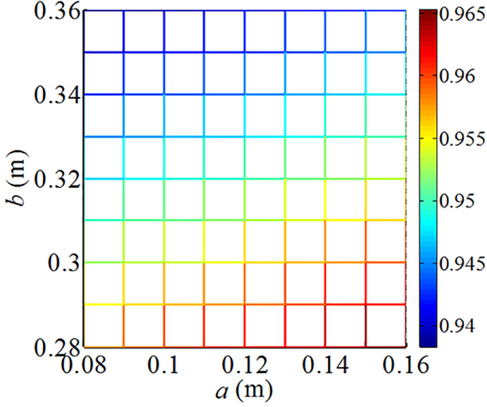
Variations of κ with respect to the size of the platform and base.
As shown in Figure 7, the global coupling index κ increases monotonously with the increment of a while decreases with that of b. Further observation shows that the size of the base has a larger effect on the coupling strength than that of the platform. Therefore, increasing the size of the base is suggested preferentially to have a low coupled system so that the real control performance can be improved.
Structural parameters effects
Variations of κ with respect to the length of active U

Variations of κ with respect to the length of active and passive limbs.
It can be seen from Figure 8 that the global coupling index κ increases monotonously with the increment of the oscillating limb’s length la2 while decreases with that of the stretchable limb’s length la1. And it seems that the length of the oscillating limb la2 has a larger effect on κ than that of the stretchable limb la1. Further observation demonstrates that the global coupling index κ decreases monotonously with the increment of the thick limb’s length lp1. And the global coupling index κ seems to keep unchanged with the increment of the length of the thin limb lp2. By comparing, it can be found that length of the active limbs has a larger effect on κ than that of the passive limb. Therefore, it is suggested to decrease length of the oscillating limb preferentially to decrease the coupling strength of the system.
Figure 9 shows variations of κ with respect to the depth of active U

Variations of κ with respect to the depth of active and passive limbs.
It can be seen from Figure 9 that the global coupling index κ increases monotonously with the increment of the U
In general, effects of the structural parameters on the system’s coupling strength are very weak, which can be found from Figures 8 and 9.
Mass parameters effects
Variations of κ with respect to mass of the 2R module are depicted in Figure 10. Herein, mA and mC are mass of the A axis and C axis. As can be seen, the global coupling index κ decreases monotonously with the increment of mass of the 2R module. Therefore, increasing mass of the 2R module properly is advised to reduce coupling strength of the system.

Variations of κ with respect to mass of the 2R module.
Combining Figures 7–10, it can be concluded that sizes of the platform and the base have an obvious effect on the global coupling strength. And effects of structural parameters of the active and passive limbs as well as mass of the 2R module are relatively low. Despite that, coupling may affect the real control performance or other indices in a large degree. Therefore, optimal design of the parallel/hybrid manipulator should be synthesized with kinematic, stiffness, and dynamic performance together.
Conclusion
Based on the rigid dynamic model, this article analyzes coupling characteristics of the Trimule robot. The main contributions of the article are drawn as follows.
A local coupling index is defined based on the off-diagonal mass matrix. Distributions of three local coupling indices are strongly position-dependent and are symmetric to the plane of x = 0 due to the mechanical features of the Trimule robot. And the three U
A global coupling index is proposed which indicates the average maximum coupling index throughout the whole workspace. Parametric analysis demonstrates that dimensional parameters and structural parameters as well as mass parameters can affect the coupling strength to an extent. And the dimensional parameters of the PKM seem to have the largest influence.
It is worth noting that optimal design of the Trimule should be conducted by considering kinematic performance, stiffness, dynamic characteristics, and coupling together, which will be published in the near future.
Footnotes
Declaration of conflicting interests
The author(s) declared no potential conflicts of interest with respect to the research, authorship, and/or publication of this article.
Funding
The author(s) disclosed receipt of the following financial support for the research, authorship, and/or publication of this article: This work is supported by the National Key Science and Technology Project (grant number 2017ZX04013001), National Key Technology Research and Development Program of the Ministry of Science and Technology of China (grant number 2015BAF11B00), and National Natural Science Foundation of China (grant number 51475320).