
Abstract
This article proposes frequency response function approximation method to identify mechanical parameters of fiber-reinforced composites. First, a fiber-reinforced composite thin plate is taken as a research object, and its natural characteristic and vibration response under pulse excitation are solved based on the Ritz method and mode superposition method, so that the theoretical calculation of frequency response function of such composite plates can be realized. Then, the identification principle based on frequency response function approximation method is illustrated and its correctness is validated by comparing with other published literature in the verification example, and the specific identification procedure is also proposed. Finally, frequency response function approximation method is applied in a study case, where the elastic moduli, Poisson’s ratios, and loss factors of the TC300 carbon/epoxy composite thin plate are identified, and the influences of boundary conditions, approximation points, total number of modes, and calculation step size on the identification accuracy and efficiency are discussed. It has been proved that the proposed method can identify mechanical parameters of fiber composite materials with high precision and efficiency.
Keywords
Introduction
Fiber-reinforced composites have excellent mechanical properties, good thermal stability, and capability on weight reduction, which are widely used in aeronautics, astronautics, automotives, naval vessels, and weapons industry.1,2 Currently, there are a large number of such composite thin walled structures, such as solar panels, aircraft engine fan blades, and large wind turbine blades. The vibration problems of such composite blades and plates, such as an excessive vibration, wear and tear, and fatigue failure, have become more and more serious due to the frequent work in harsh environments, attracting an increasing number of researchers to solve these problems.3,4 The mechanical property parameters of fiber-reinforced composite materials usually include longitudinal elastic modulus, transverse elastic modulus, in-plane shear modulus, Poisson ratio, and loss factor. Accurately identifying these mechanical property parameters is the basis of analyzing the natural property and vibration response of composite structures, which has an important engineering and academic significance in the field of theoretical analysis, dynamic design, fault diagnosis of composite structures, and so on.
At present, great progress has been made in the identification of mechanical property parameters of fiber-reinforced composites. For example, Deobald and Gibson
5
presented a material parameter identification method of a fiber-reinforced composite thin plate by combining modal analysis and Rayleigh–Ritz method, and the material parameters of the composite plate, such as the elastic moduli and Poisson’s ratio values, were obtained based on the results of bending stiffness
Although the above researches have deeply investigated the identification technology of mechanical property parameters by combining theory and experiment, until now, most of them only utilize natural frequencies and modal damping ratio extracted from frequency response function (FRF) to identify elastic modulus and loss factor values of fiber-reinforced composites, and the whole information of FRF has not be fully employed to identify mechanical parameters. On one hand, FRF itself can objectively reflect the stiffness, damping, and other vibration information of the mechanical structure system, which is independent to the external excitation loads and its disturbances. On the other hand, FRF can also be easily obtained by the modal test technique, and its vertical axis represents the displacement admittance, that is, the inverse of the dynamic stiffness characteristics, which has the close relation with mechanical feature parameters of the structure system. Therefore, it is feasible that we can use the FRF data to identify the concerned elastic moduli and loss factors along the longitudinal, transverse, and shear direction of fiber-reinforced composites.
In this research, we try to find out a new identification solution for mechanical property parameters of fiber-reinforced composites, and frequency response function approximation method (FRFAM) is proposed to reach the target. In section “Theoretical calculation of FRF of fiber-reinforced composite thin plates,” first, a fiber-reinforced composite thin plate is taken as a research object, and its elastic moduli in different fiber directions are expressed as complex forms. Then, its natural characteristic and vibration response under pulse excitation are solved based on the Ritz method and mode superposition method, so that the mathematical calculation of FRF of such composite plates can be realized. In section “The identification principle based on FRFAM and its verification,” the identification principle based on FRFAM is illustrated and its correctness is validated by comparing with other published literature in the verification example. Finally, we go on to propose the specific identification procedure in section “Identification procedure,” and in section “A case study,” FRFAM is applied in a study case, where the elastic moduli, passion ratios, and loss factors of the TC300 carbon/epoxy composite thin plate are identified, and the influences of modal order, boundary conditions, and approximation points of such methods are also discussed. It has been proved that the proposed method can identify mechanical parameters of fiber composite materials with high precision and efficiency. On one hand, it can be used in the theoretical modeling and analysis process. On the other hand, it can be applied in the field of dynamic optimal design and fiber material failure prediction.
Theoretical calculation of FRF of fiber-reinforced composite thin plates
The fiber-reinforced composite thin plate is made of fiber and matrix material with n layers, as seen in Figure 1. First, set up the coordinate system

A theoretical model of fiber-reinforced composite thin plate.
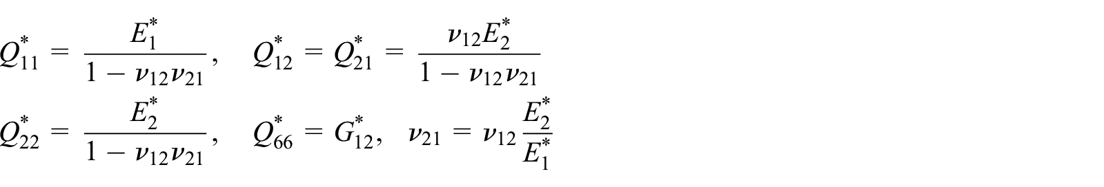
Considering the influence of fiber direction, the elastic moduli of fiber-reinforced composites 17 can be expressed as

where
Based on the classical lamination theory, the displacement field can be expressed as


where
Because the concerned fiber-reinforced composite thin plate is symmetrical between the middle surface, and the displacement perpendicular to the xoy plane is decoupled from the displacement in the xoy plane, the displacements


The bending curvatures

Then, the strain of any point of composite plate can be simplified as

For the orthotropic material, the stress–strain relationship in the fiber coordinates can be defined as

where
When an angle of

where
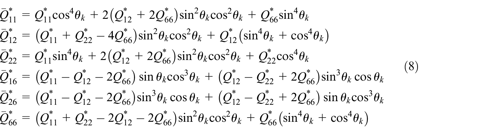
where k represents the kth layer of composite plates and
The bending and twisting moment resultants 18 in composite plates can be expressed as

where
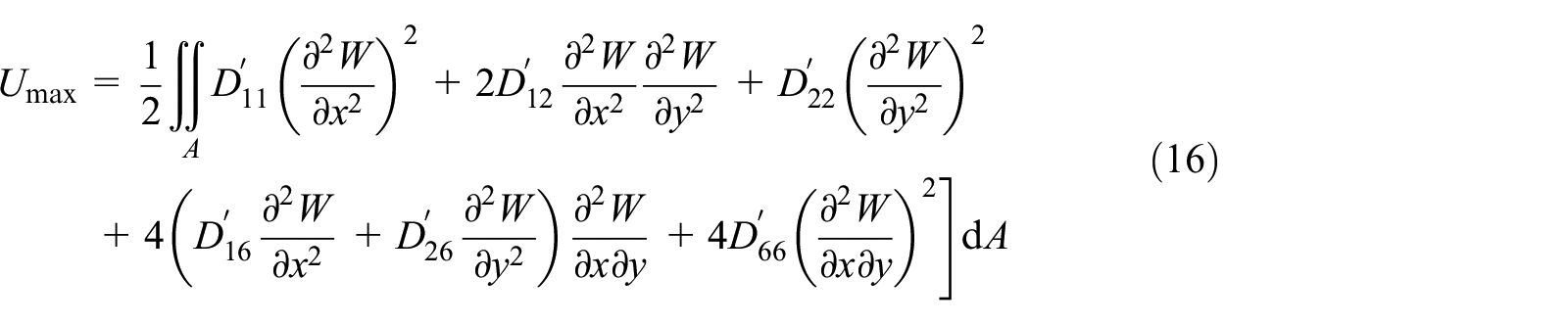
The bending strain energy stored in the composite thin plate can be expressed as

where A represents the area of middle surface of composite plate.
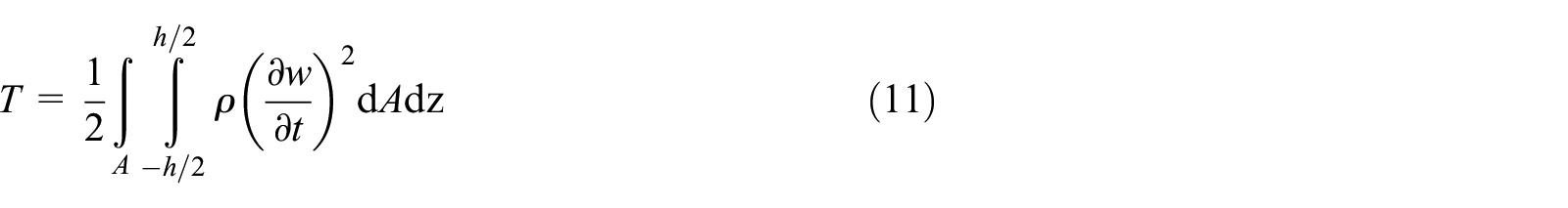
The kinetic energy of composite thin plate can be expressed as
Assuming that the displacement of any vibration response point L

where

where
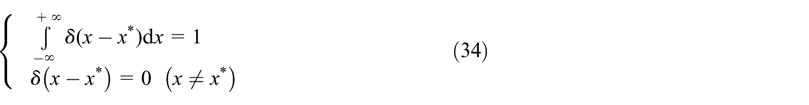
Then, the orthogonal polynomials can be obtained by implementing orthogonalization operation on polynomial function, which should satisfy the boundary condition of composite plate, and these polynomials have the following expressions

where

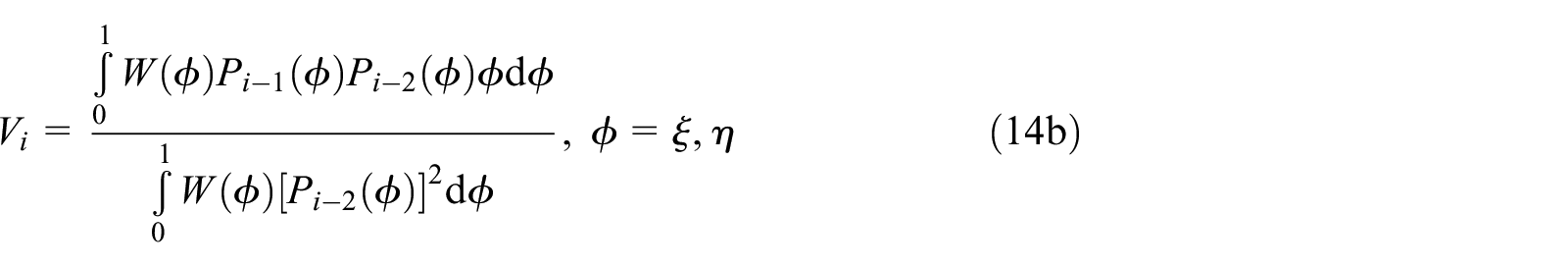
where

For completely free boundary condition, we can set
Then, substituting equation (12) into equations (10) and (11), we can obtain the maximum bending strain energy

where
Next, define the Lagrangian energy function L as

By minimizing partial derivative of the Lagrangian energy function L with respect to

Substituting equation (18) into equation (19), the eigenvalue equation can be obtained as

where
In order to make equation (20) have nonzero solution or nontrivial solution, the determinant of the coefficient matrix should be equal to zero

By solving equation (21), the natural frequencies of the composite thin plate can be obtained. Then, substituting the eigenvector corresponding to a certain natural frequency into equation (13), the modal shape corresponding to this natural frequency can be easily obtained. Repeating the steps above, the all concerned modal shape will be obtained.
After the natural frequencies and modal shapes of the composite plate are solved, assume the pulse excitation

where
Considering the dynamic balance of composite plate and ignoring damping and inertia moment, the following equations can be obtained


where
Substituting equation (9) into equation (24), the forced vibration differential equation of composite thin plate without considering damping can be simplified as

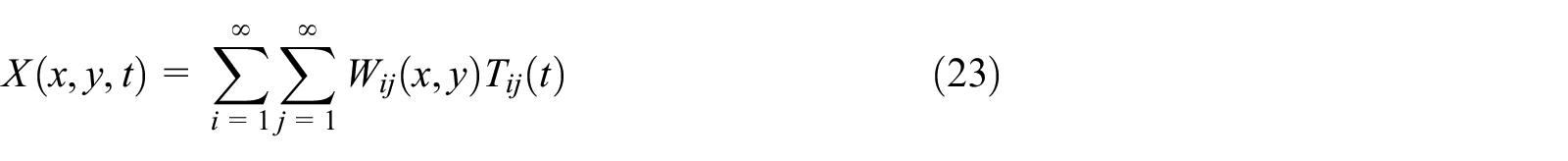
According to modal shape superposition method, the displacement response of a continuous system can be expressed as the series of modal shape function, and the partial differential equations under physical coordinates can be converted to the second-order ordinary differential equations under generalized coordinates. Thus, the continuous system would be simplified as the single degree of freedom system.
Substituting equation (23) into equation (25), the following equation is obtained

Besides, according to displacement variation principle, the modal shape function

Substituting equation (27) into equation (26) and through simplifying, the following equation can be derived

Then, multiply
Furthermore, by utilizing the orthogonality of modal shape of plates, which has the following form

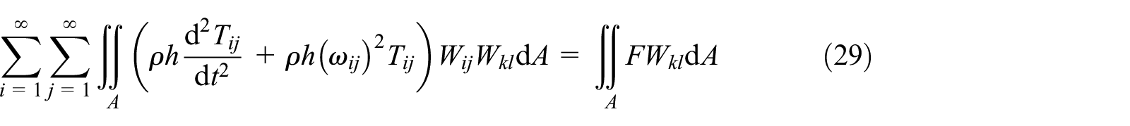
The generalized vibration differential equation without damping can be expressed as

where


Meanwhile, considering the following property of the function of
The generalized force

Similarly, under the assumption of small damping, the generalized vibration differential equation with damping can be expressed as

where
At the zero initial condition, the solution of equation (36) can be expressed as Duhamel integral form, which has the following expression

where
Equation (37) can be solved using Simpson numerical integration, and substituting its results into equation (23), the vibration response

Finally, the time-domain wave of excitation force and displacement response based on self-designed MATLAB program can be plotted, and the fast Fourier transformation (FFT) operation is applied to excitation and response data. Consequently, the Fourier function of

The identification principle based on FRFAM and its verification
The identification principle
In section “Theoretical calculation of FRF of fiber-reinforced composite thin plates,” the FRF of composite thin plates under pulse excitation is obtained through theoretical method. However, in most cases, the experimental modal test is mainly conducted to obtain the FRF expressed in equation (38). If the experiment FRF data can be first obtained, while the theoretical FRF data can also be calculated by theoretical method, then we can modify the theoretical FRF data with the experimental FRF data as a reference. Because the mechanical parameters of fiber-reinforced composites, such as
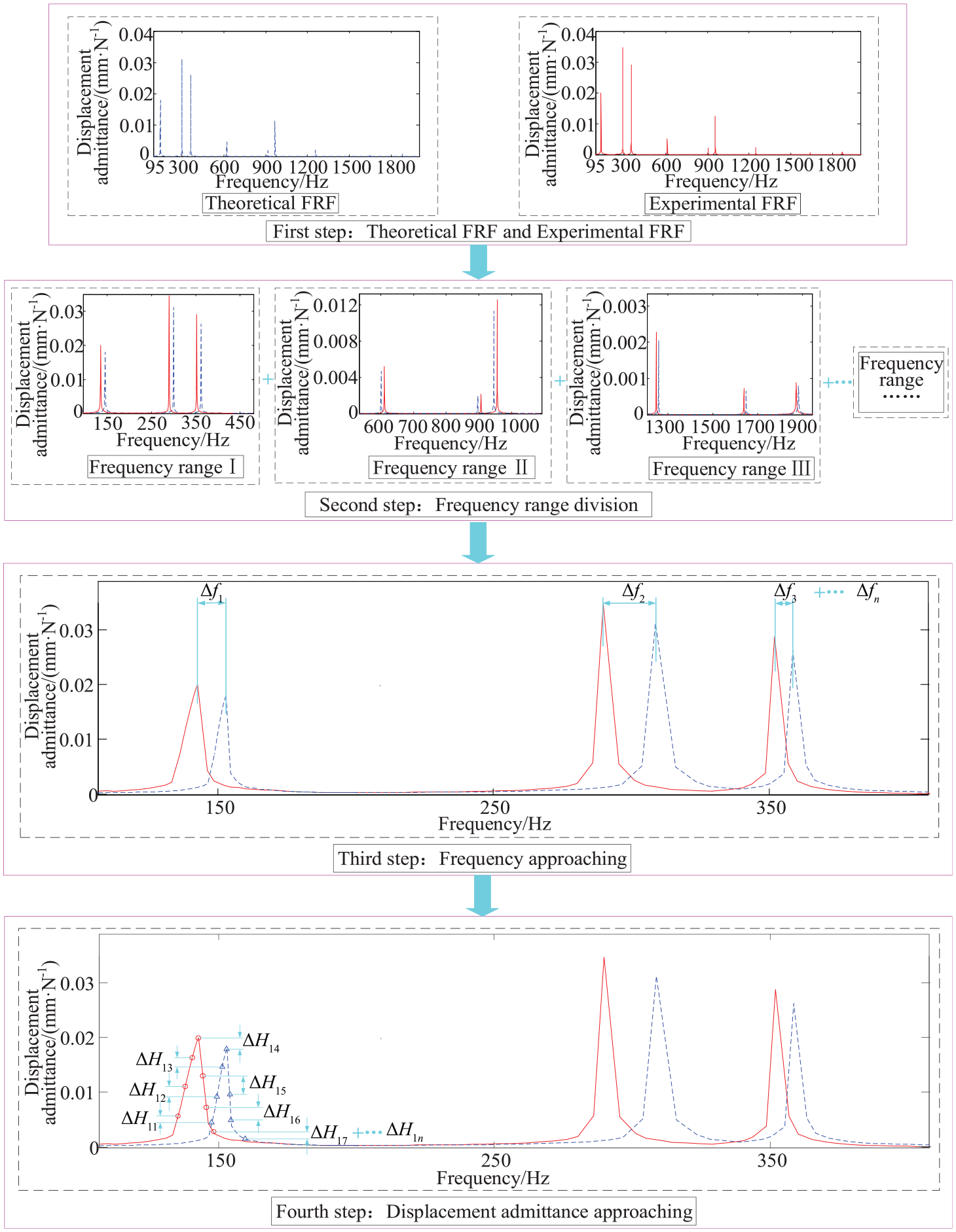
The schematic diagram to obtain the FRF of composite thin plates under pulse excitation by the above two methods is shown in Figure 2, which mainly contains three mapping forms: (1) the mapping between excitation force in the experiment produced by the hammer and pulse excitation force in the theoretical calculation, (2) the mapping between experimental vibration response and theoretical vibration response, and (3) the mapping between experimental test procedure and theoretical analysis procedure. By applying pulse excitation force at same position of the composite plate and obtaining the resulting vibration response at same location, we can modify the mechanical parameters using FRFAM. Finally, when the theoretical FRF can approximate the experimental FRF closely, the input mechanical parameters in the theoretical calculation can be equivalent to the real mechanical parameters of the composite plate. Figure 3 gives the schematic diagram of identification principle of this method.

The schematic diagram to obtain FRF of composite thin plate.
The schematic diagram of identification principle.
First, the experimental FRF and theoretical FRF with the two methods described in the previous paragraph should be obtained, which can be plotted on the same graph, as shown in Figure 3. Then, the whole concerned frequency range can be divided into multiple frequency ranges, and in each frequency range, two to three modes of composite thin plate should be included. Finally, we can use the approaching calculation techniques to construct the frequency relative error function
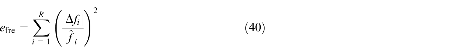
where R represents the number of modes in the whole frequency range,
Then, taking the average material parameters as the center, such as

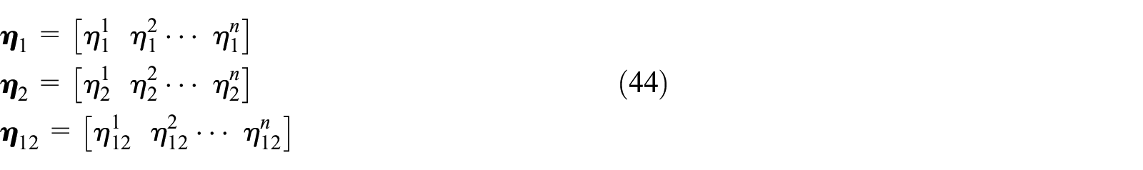
Furthermore, select an appropriate step size g (e.g. g = 1%) in the above range and construct iteration vectors of material parameters, such as

where
By iteratively calculating the material parameters in a permutation and combination manner, we can obtain the optimum estimation results of
Similarly, by extracting the multiple resonance peaks from the experimental FRF and theoretical FRF, we can construct the admittance relative error function

where i is the ith resonance peak, S is the number of approaching points on the ith resonance peak,
Next, take the maximum loss factor
where
According to modal strain energy method, the relations between modal loss factors and loss factors in different fiber direction can be expressed as

where U is the total strain energy of the composite plate,


Then, according to the relation between modal damping ratios and modal loss factors, the modal damping ratio

Finally, by iteratively calculating the loss factors in a permutation and combination manner, the optimum estimation results of
Verification example
In order to verify the correctness of the method proposed in this article, we employ FRFAM to identify the mechanical parameters of graphite/epoxy composite thin plates in Han and Lee
21
with laminate configuration of
The mechanical parameters given in Han and Lee 21 and identified in this research by FRFAM.

The natural frequencies and modal damping ratios measured in Han and Lee 21 and calculated in this research by FRFAM.

By utilizing the above data of dimensions, laminate configuration, and the experimental FRF of composite plate, the calculated FRF curve can be obtained by FRFAM. In addition, the identified mechanical parameters as well as the calculated errors are also listed in Table 1. Finally, the identified mechanical parameters are input into the theoretical model to recalculate the natural frequencies and modal damping ratios, as seen in Table 2, and the errors between the calculated frequency and damping results in this research and the ones given in Han and Lee 21 are also listed in Table 2.
From Table 1, we can find that the maximum error between the identified material parameters and the parameters given in Han and Lee 21 is no more than 6.45%. In addition, from Table 2, we can compare the natural frequency and modal damping ratio results calculated by this research with the results given in Han and Lee, 21 then we can find out that the maximum errors of natural frequencies and modal damping ratios are less than 9.40% and 10.17%, respectively, which are also within an acceptable range. Therefore, the correctness and practicability of the proposed method can be verified.
Identification procedure
In this section, the identification procedure of mechanical parameters of fiber-reinforced composites is summarized, which is realized based on self-designed MATLAB program and can be divided into the following steps.
Solve natural characteristic and vibration response
First, a fiber-reinforced composite thin plate is taken as a research object, and its theoretical model is established based on the classical lamination theory. Meanwhile, its elastic moduli in different fiber directions are expressed as complex forms, and the natural characteristic and vibration response can be solved using Ritz method and mode superposition method, respectively.
Solve FRF of the composite thin plate under pulse excitation
Using equation (38) to calculate vibration response
Measure FRF of composite thin plate with the hammer
If the FRF measurement is done under the free boundary condition, it is necessary to use a rubber rope to hang the tested plate specimen, and if the FRF measurement is done under the constrained boundary condition, it is needed to ensure that the composite plate is effectively clamped by the fixture tools. In addition, in order to get good FRF results, lightweight accelerometer should be used to get response signal to reduce the effects of the additional mass and stiffness, and the FRF results and the coherence function results need to be tested simultaneously. It is suggested that their final values should be the average results, which are measured at least three times. Then, the coherence function can be used to evaluate the test accuracy of FRF data. If the coherence coefficients are above 0.9, the corresponding FRF results are accepted, otherwise the measurement should be re-conducted several times.
Identify the elastic coefficients
by the natural frequency approaching technique
In this step, we should separate the concerned frequency range into several sub-ranges and identify the theoretical and experimental natural frequencies in each sub-range, and then select an appropriate step size to construct iteration vectors of material parameters, so that the frequency relative error function
Identify the loss factors
,
, and
by the displacement admittance approaching technique
This step is similar to the step (4), yet the approximating object is changed to the displacement admittance of theoretical and experimental FRF. First, set the number of approaching points in each sub-range of FRF data and construct iteration vectors of loss factors with an appropriate step size, so that the displacement admittance relative error function
A case study
In this section, a TC300 carbon/epoxy composite plate is taken as a research object and its mechanical parameters are identified by FRFAM. The studied plate specimen is symmetrically laid, which is cut from the fiber composite material with total of 21 layers and laminate configuration of ((0/90)5/0/(90/0)5). The length, width, and thickness are 230, 130, and 2.36 mm, respectively, and each layer has the same thickness. Besides, its material parameter is provided by the manufacturer, with the longitudinal elastic modulus E1 = 105.0 GPa, transverse elastic modulus E2 = 7.9 GPa, shear modulus G12 = 4.2 GPa, Poisson’s ratio
Test system
In order to obtain the FRF of fiber-reinforced composite plates under pulse excitation, the FRF test system is set up. The instruments used in the test are as follows: (1) BK 4517-001 lightweight accelerometer, (2) LMS SCADAS 16-channel Mobile Front-End, (3) Dell M7700 computer and LMS TestLab 10B software, and (4) PCB 086C01 Hammer. After the repeated testing and comparison, the pulse excitation is applied at the point Q, which is 100 mm from the left edge and 30 mm from the upside edge of the composite plate. In addition, the accelerometer is glued firmly at response point L by super glue 502, which is 40 mm from the left edge and 30 mm from the downside edge of the composite plate. Then, the following setups and parameters are chosen: (1) sampling frequency of 3200 Hz, (2) frequency resolution of 0.125 Hz, and (3) force-exponential window for excitation signal and exponential window for response signals. Consequently, we can employ pulse excitation technique to carry out modal test, and by analyzing the response signal in frequency domain with LMS software, the natural frequency and the damping ratio of each mode can be obtained with the half power bandwidth method. The real picture of the FRF test of the composite thin plate under different boundary conditions can be seen in Figure 4(a) and (b).

The real picture of the FRF test of the composite thin plate under different boundary conditions: (a) free boundary and (b) cantilever boundary.
Identification results of mechanical parameters under different boundary conditions
In this section, the FRFs of the composite plate under the free and cantilever boundary conditions are measured. First, pulse excitation is applied on the tested plate under the free boundary condition by the hammer, and the excitation signal and response signal are recorded at the same time by the data acquisition instrument. Since the lightweight accelerometer is used, we can only get FRF in the form of acceleration admittance. Then, after applying the integral operation, we can get FRF results in the concerned form of displacement admittance. Finally, we can use the approaching calculation techniques to draw the theoretical FRF of composite thin plate repeatedly, and when the frequency relative error function

Theoretical and experimental FRFs in different frequency ranges under the free boundary condition: (a) frequency range of 100–500 Hz, (b) frequency range of 600–900 Hz, and (c) frequency range of 900–1500 Hz.
Then, by applying the same test technique, the FRF data under the cantilever boundary condition can be obtained. Consequently, the theoretical and experimental FRF in different frequency ranges can be plotted using the approaching calculation techniques, as seen in Figure 6. If the constructed frequency relative error function

Theoretical and experimental FRFs in different frequency ranges under the cantilever boundary condition: (a) frequency range of 0–200 Hz, (b) frequency range of 200–500 Hz, and (c) frequency range of 600–1200 Hz.
Finally, set five approximation points and calculation step size of 1% in the self-designed MATLAB program, and the mechanical parameters of fiber-reinforced composites, such as
The identified mechanical parameters of fiber-reinforced composite by FRFAM under the two different boundary conditions and their errors.

Identification results under different total number of modes
Since the identification results of mechanical parameters of fiber-reinforced composite under free boundary condition are more accurate, in the following section, the influence of different total number of modes on the identification results under such boundaries are discussed. Still use the same setting in section “Identification results of mechanical parameters under different boundary conditions” with five approximation points and calculation step size of 1% in the MATLAB program, yet choose FRF data in the three different numbers of modes, such as 3 modes, 5 modes, and 7 modes, to identify mechanical parameters of the fiber-reinforced composite by FRFAM. Table 4 lists the identified results, the corresponding errors, and time expenditures.
The identified mechanical parameters of fiber-reinforced composite by FRFAM under different total number of modes, the corresponding errors, and time expenditures.
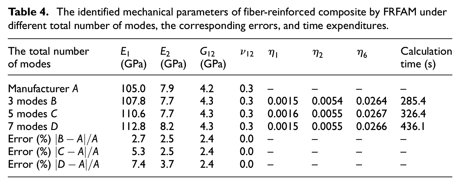
As can be seen from Table 4, the elasticity moduli and computation time will be rising gradually with the increase of the selected total number of modes of the fiber-reinforced composite, and the theoretical calculation errors also show an increasing trend. Therefore, it is not true that when the higher number of mode is considered, the more accurate identification results of mechanical parameters will be obtained, and how close the theoretical FRF can approach the experimental FRF is what counts most of all. Therefore, in this example, the experimental FRF in the first three modes is the better choice to construct frequency relative error function and admittance relative error function in FRFAM.
Identification results under different approximation points
In this section, in order to discuss the influence of the number of approximation points on identification accuracy and identification efficiency of mechanical parameters of fiber-reinforced composite, 3, 5, 7, and 9 approximation points are selected in the MATLAB program with the unchanged calculation step size of 1% and free boundary condition. Then, when the frequency relative error function and admittance relative error function in the first three modes get the minimum value, the optimum mechanical parameters can be identified, as seen in Table 5, and the corresponding time expenditures are also listed in Table 5.
The identified mechanical parameters of fiber-reinforced composite by FRFAM under different approximation points and time expenditures.

As can be seen from Table 5, the identification results of elasticity moduli
Identification results under different calculation step sizes
In this section, in order to evaluate FRFAM objectively, the influence of different calculation step sizes on identification accuracy and identification efficiency of mechanical parameters of the fiber-reinforced composite is discussed. First, choose the FRF data under free boundary condition in the first three modes and set five approximation points in the MATLAB program. Then, select the step size of 20%, 7.5%, 3.5%, 1%, 0.5%, and 0.1% to identify the concerned mechanical parameters along the longitudinal, transverse, and shear direction of the fiber composites. The identification results under different calculation step sizes and their time expenditures can be seen in Table 6, from which it can be discovered that calculation step sizes will have an important impact on the identification accuracy and efficiency. With the decrease of calculation step size, the theoretical calculation errors show a decreasing trend compared with the ones provided by the manufacturer, but the time expenditures in the calculation will increase sharply. Therefore, it is necessary to choose appropriate calculation step sizes. In this example, the step size of 1% is accurate enough to finish the FRF approximation work and its calculation time is less than 300 s, which is within an acceptable range. So, it can be used as the reference in the similar FRF approximation calculation program for the identification of mechanical parameters of other fiber composites.
The identified mechanical parameters of fiber-reinforced composite by FRFAM under different step sizes and their time expenditures.

Conclusion
In this article, FRFAM is proposed to identify the mechanical parameters of fiber-reinforced composites, and its correctness and practicability have been validated in the verification example and the case study. It has been found that the boundary conditions, approximation points, total number of modes, and calculation step size have an important impact on the identification accuracy and efficiency. Because the identified errors of elastic moduli and Poisson’s ratio under the cantilever boundary condition are larger than the ones under the free boundary condition, it is suggested that the experimental FRF data should be obtained under free boundary condition. Meanwhile, after comparing with the identified results, the step size of 1% and five to seven approximation points would be accurate enough to finish the FRF approximation work. Finally, it is not true that when the higher number of mode is considered, the more accurate identification results of mechanical parameters will be obtained. The identification accuracy of FRFAM depends on how close the theoretical FRF can approach the experimental FRF, and usually the experimental FRF in the first three modes is the better choice to establish the frequency relative error function and admittance relative error function in FRFAM.
Footnotes
Declaration of conflicting interests
The author(s) declared no potential conflicts of interest with respect to the research, authorship, and/or publication of this article.
Funding
The author(s) disclosed receipt of the following financial support for the research, authorship, and/or publication of this article: This study was supported by the National Natural Science Foundation of China (grant nos. 51505070 and U1708257), the Fundamental Research Funds for the Central Universities of China (grant nos. N160313002, N160312001, N170302001, N180302004, N180703018, and N180313006), the Scholarship Fund of China Scholarship Council (CSC; grant no. 201806085032), and the Key Laboratory of Vibration and Control of Aero-Propulsion System Ministry of Education, Northeastern University (grant no. VCAME201603).