
Abstract
By applying finite element software ANSYS/LS-DYNA, finite element models of front bulkhead and main cabin are established, which aims to assess the dynamic response of fuselage structures impacted by tire fragment under bursting mode. Besides, dynamic characteristics of the two fuselage structures impacted by tire fragment are simulated and critical damage velocities of each working condition are obtained. The results show that composite front bulkhead cannot bear the impact load of front tire fragment at the velocity of 100 m/s, but aluminum alloy front bulkhead can. Main cabin with two properties both can bear the impact loads of front and main tire fragments. When impacted by front tire fragment, critical damage velocity of front bulkhead is approximately half of that of main cabin, while critical damage velocity of aluminum alloy fuselage is larger than that of composite fuselage. However, when impacted by main tire fragment, critical damage velocity of aluminum alloy main cabin is less than that of composite main cabin. Furthermore, maximum contact pressure of composite fuselage is 3–3.3 times than that of aluminum alloy fuselage. The difference in concave deformation is not significant when impacted by front tire fragment, but the difference is great when impacted by main tire fragment.
Keywords
Introduction
With the starts of large-scale civil aircraft project, the development of new fuselage structure is an effective means to improve fuselage life, economy, safety, comfort, and reliability of large passenger aircraft. Aircraft tire is a very important component which requires high safety and reliability. The safe taking off and landing of aircraft must be accomplished by the unique functions of aviation tire. 1 The relevant data show that accident rate caused by aircraft tire bursting is the highest in all influential factors of aviation accidents, for example, the Douglas DC-10 and Boeing B747 both have experienced serious accidents due to tire bursting. The famous supersonic Concorde aircraft also has experienced accident crash caused by tire bursting. In 2004, the CRJ200 overran the runway due to the brake failure caused by tire bursting. 2
Aircraft tire is easy to burst and fail in the process of taking off and landing. The strong airflow and tire fragment caused by tire bursting may lead to serious impact damage for fuselage. This high-velocity impact may cause fuselage deformation, panel damage, and even fuselage rupture, which affects the aerodynamic performance of aircraft seriously and threatens the normal safety flight of aircraft. Therefore, tire bursting is the particular risk which must be considered in airworthiness regulations. There are usually four kinds of tire bursting modes, namely, tire fragment, jilt tire, air jet pressure, and rim fragment. 3 The high-velocity tire fragment may breakdown the aircraft panel and fuel tank, which brings great threat to the safety of aircraft. Fuselage is the most important component in aircraft. So, in order to ensure the safety performance of fuselage, it must be able to have enough strength to resist impact load when it is strongly suffered from external impact load. Therefore, it is of great practical significance to study the impact resistance of fuselage when it is suffered from the impact of tire fragment.
Since the last century, many scholars have done numerous researches on the impact resistances of aircraft structure and achieved fruitful results. Since 1960s, the Western countries have obtained a large number of effective damage data through the experiment of high-velocity fragment that impacts fuselage. The related analysis models were established, and the damage assessment as well as repair manual was compiled. 4 At present, the coupling method and decoupling method are mainly used in the numerical simulation of impacting. Where, the coupling method includes contact–impact coupling algorithm, fluid–structure coupling algorithm, and smoothed particle hydrodynamics (SPH) method.5,6 Coupling method is to combine the projectile and fuselage models to solve the impact problem. These two models are connected by the compatibility conditions of contact surfaces. The dynamic responses of fuselage structure, projectile, and the impact force can be obtained through solving the simultaneous equations. The decoupling method is to ignore and simplify the models which have less influence on the study, and the main model is only analyzed. Napoli et al., 7 Caputo et al.,8,9 and Gulida et al. 10 introduced the modeling strategies and applications of finite element (FE) method, multibody (MB) method, hybrid FE/MB method, and coupled FE/MB method. The advantages and limits of each method were also analyzed in detail. For example, the coupling method can well simulate the whole impact process and are more versatile than FE method and hybrid method, so this method is widely used at present. The main constitutive models applicable to rubber material are Mooney Rivlin model, Yeoh model, and Ogden model. The main failure criteria which apply to composite material are Chang–Chang criterion, maximum stress criterion, Tsai–Hill criterion, Tsai–Wu criterion, and Hashin criterion. 11 The researches of fuselage impacted by projectile, tire fragment, and other external objects are mainly based on experiment together with theory analysis and numerical simulation. 4 Disimile et al. 12 carried out the experiment by using tungsten alloy, steel, and aluminum alloy projectiles to impact the fuel tank in aircraft and obtained the change law of water hammer in different positions. Karagiozova and Mines 13 studied the impact resistance of fuel tank subjected to large-size tire fragment through experiment and numerical simulation. The results show that numerical simulation can simulate the process of impact experiment effectively. Wang and colleagues14,15 studied the impact response of windshield impacted by bird and got the displacement–time curves of windshield structure, and the calculation results coincide well with the experiment values. Chen et al. 16 adopted PAM-CRASH software to study the hydrodynamic ram of composite fuel tank; the failure and damage characteristic of fuel tank were analyzed, and the results show that holistic damage in multiple walls can appear easily in composite fuel tank compared with metal fuel tank. Heimbs et al. 17 simulated the hydrodynamic ram of three different T-type composite fuel tanks impacted by fragment projectile at a high velocity through experiment and simulation, and the accurate modeling method was obtained and the structure of fuel tank based on residual strength and structure integrity was improved. Caputo et al. 9 compared the reaction forces of a regional aircraft landing gear through stick model, MB model, and three-dimensional (3D) full-FE model. The dynamic behaviors of the landing gear were investigated through numerical simulation and experiment. The results show that a good level of accuracy can be achieved by the three established numerical models. Perfetto et al. 18 studied the dynamic response of full-composite fuselage section through drop test and numerical simulation. The FE model of a full-scale 95% composite fuselage under vertical drop test was established, and the numerical results were validated by experiment. The results show that a good agreement can be achieved between numerical simulation and experiment results. In the previous work, we 19 have studied the impact resistance of covering caps with different material properties in fuel tank which was impacted by rubber and titanium alloy projectiles; the critical damage velocity was obtained and influence law of impact position, impact angle, and impact energy on the impact resistance of covering caps in fuel tank were discussed. In general, the above studies on impact resistance of fuselage structures impacted by projectile have important reference value, but the studies on front bulkhead and main cabin impacted by rubber fragment are rare and have not seen the relevant reports. There is no mature evaluation system for the impact resistance of front bulkhead and main cabin, and the systematic researches on the design of fuselage structure about passenger aircraft are urgently needed. Therefore, it is very necessary to study the impact resistance of front bulkhead and main cabin.
Using FE software ANSYS/LS-DYNA, the dynamic characteristic of front bulkhead and main cabin impacted by front tire fragment and main tire fragment under bursting mode were simulated in this article. The impact resistance of front bulkhead and main cabin with different material properties was discussed. The failure models of aluminum alloy and composite materials were put forward. The critical damage velocity, contact pressure, and concave deformation of each working condition were also studied. The research achievements can be applied to the impact resistance design of fuselage structure, which has important reference significance to evaluate the impact resistance and design scheme of fuselage structure.
Calculation model description
FE model and material properties
At present, with the fast development of aviation material, composite materials become more and more widely used in aircraft. But aluminum alloy also has some irreplaceable advantages compared with composite materials and is still used widely in main bearing components, stiffeners, and ribs. 20 The metal material type adopted in this study is an Al01 aluminum alloy, one of the main structure materials in aviation industry, embodying lots of advantages such as high tensile strength, toughness, fatigue strength, good heat resistance, good processability, and excellent welding performance.
In order to compare the impact resistance of fuselage impacted by different size tire fragment under bursting mode, the dynamic response of fuselage impacted by front tire fragment and main tire fragment is studied. The structure models of front bulkhead and main cabin are established based on coupling algorithm. Front tire fragment impacts front bulkhead and main cabin, while main tire fragment impacts main cabin only. Front bulkhead is a rectangular plate with a size of 2740 mm × 1040 mm and the thickness is 3 mm. The structure model of front bulkhead is shown in Figure 1(a). Main cabin is a semicircle frame, and its diameter is D = 3856 mm, width is W = 1110 mm, the distance between ribs is d = 530 mm, the distance between stiffeners is d = 150 mm, and the thickness of panels, ribs, and stiffeners is evenly 3 mm. The structure model of main cabin is shown in Figure 1(b). The material properties of front bulkhead and main cabin are both Al01 aluminum alloy and T700/BA9916 composite material, respectively. When material property of fuselage is T700/BA9916 composite material, the thickness of each layer is 0.125 mm, and the total thickness of panel, rib, and stiffener is 3 mm, respectively. The stacking sequence of composite laminated is [45°/0°/−45°/90°/−45°/0°/45°/0°/45°/90°/−45°/0°]s.
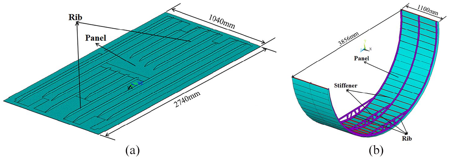
Structure models of (a) front bulkhead and (b) main cabin.
According to the relevant civil aircraft airworthiness regulations, front tire studied in this article is the 30 × 8.8 R15 Michelin tire and main tire is the 46 × 17.0 R20 Michelin tire. Thickness of the two tire fragments is the full thickness of tire tread plus the thickness of outer cord thread, as given in Table 1. The shape of the two tire fragments is square. For front tire fragment, the mass is 1.13 kg with physical dimension of 211 mm × 211 mm × 12.4 mm. For main tire fragment, the mass is 5.60 kg with physical dimension of 405 mm × 405 mm × 16.2 mm. Impact velocity of the two fragments is 100 m/s, which is the velocity of tire when aircraft gets off the ground. Impact point is the 45° angular of fragment, and impact position of front bulkhead and main cabin is the center position. The contact–impact coupling algorithm is adopted for the dynamic response analysis of fuselage based on Lagrange element. Each part of fuselage is divided into quadrilateral element, and the projectile is divided into hexahedral element. As the modeling process of fragments adopted is solid element, fragments are defined as 3DSolid164 element. This type of element is defined as eight nodes having the following degree of freedom at each node: translations, velocities, and accelerations in the nodal X, Y, and Z directions. The structure models of front bulkhead and main cabin are very complex, and each part of the fuselage structure is composed of composite material. Therefore, if the front bulkhead and main cabin are established using solid element, the computational time will be very large. In addition, as the panel of main cabin is a semicircle, it cannot define the fiber direction of each layer. If the fuselage structures are established using shell element, the computational time can be reduced. The shell element is also very suitable for studying the impact response of composite structure according to the keyword file in ANSYS/LS-DYNA. Therefore, front bulkhead, panel, rib, and stiffener are defined as Thin Shell163 element. This type of element has four nodes and 12 degrees of freedom per node. The shapes of fragment, front bulkhead, panel, and stiffener of main cabin are regular, so sweeping is adopted to mesh. But the shape of the rib is very complex, so free meshing is adopted. For the main cabin impacted by front tire fragment and main tire fragment, there are 324 elements for front tire fragment, 625 elements for main tire fragment, 2928 elements for panel, 261 elements for ribs, and 504 elements for stiffeners. There are 6067 and 5444 nodes in total of these two FE models, respectively. The FE models are shown in Figure 2(a) and (b). For the front bulkhead impacted by front tire fragment, there are 324 elements for front tire fragment and 7799 elements for front bulkhead. There are 8720 nodes in total and the FE model is shown in Figure 2(c).
Aircraft tire parameters.


Finite element models of each fuselage structure impacted by tire fragment. (a) Main cabin impacted by main tire fragment. (b) Main cabin impacted by front tire fragment. (c) Front bulkhead impacted by front tire fragment.
In ANSYS/LS-DYNA software, contact_automatic_surface_to_surface contact algorithm is adopted between tire fragment and front bulkhead, contact_one_way_surface_to_surface contact algorithm is adopted between tire fragment and panel of main cabin, and the contact elements are Targe169 and Contact 171. Contact_automatic_nodes_to_surface contact algorithm is adopted between tire fragment and rib and stiffener, and the contact element is Contact 48. Contact_automatic_single_surface contact algorithm is adopted between rib and stiffener, contact_tied_shell_edge_to_surface_offset contact algorithm is adopted between panel and rib as well as panel and stiffener, and the contact element is Contact 48. The algorithm of contact is penalty. The fixed constraint is adopted in the surrounding sides of front bulkhead and the bottom edges of main cabin, while the outer two ribs are fixed in X-direction displacement only. The unified system of unit ton-mm-s is adopted. Step length factor is 0.6, solution time is 100 ms, and output step number is 1000. The keyword file impact.k is output and then submitted to LS-DYNA solver after it is modified in LS-PrePost. The main material properties of rubber, aluminum alloy, and T700/BA9916 composite material are given in Tables 2–4, respectively.
Main material properties of aluminum alloy (unit: ton-mm-s).

Main material properties of rubber (unit: ton-mm-s).

Main material properties of T700/BA9916 composite material (unit: ton-mm-s).

In Tables 2–4, ρ is the density, E is the elastic modulus, and μ is Poisson’s ratio. σ0 is the initial yield stress. FS represents the failure strain of Al01 aluminum alloy. A and B are the constants of rubber material. E1 and E2 are the longitudinal and transverse elastic moduli, respectively. G12, G13, and G23 are the shear moduli. Xt and Xc are the longitudinal tensile and compressive strengths, respectively. Yt and Yc are transverse tensile and compressive strengths, respectively. Sc is the shear strength.
Material constitutive models
The 54# MAT-ENHANCED-COMPOSITE-DAMAGE constitutive model in LS-DYNA is used for the dynamic failure simulation of anisotropic composite material by Chang–Chang failure criterion. The Chang–Chang failure criterion and its corresponding stiffness degradation method are given as follows. 19 , 21 , 22
For tensile fiber mode
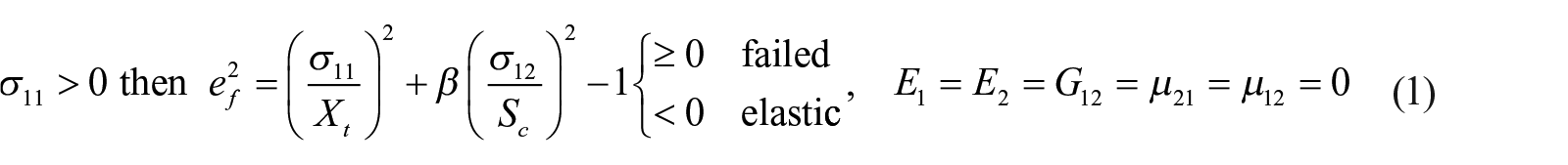
For compressive fiber mode
For tensile matrix mode

And for compressive matrix mode

where σ11 and σ22 are the yield stresses of fiber and matrix, respectively. μ12 and μ21 are Poisson’s ratio.
As the work hardening phenomenon of aluminum alloy must be considered in the process of impacting, 003# PLASTIC_KINEMATIC constitutive model is used for the dynamic failure simulation of aluminum alloy. Kinematic, isotropic, or a combination of kinematic and isotropic hardening can be specified by varying β between 0 and 1. β is equal to 0 for kinematic hardening and β is equal to 1 for isotropic hardening. The maximum strain criterion is used to define elements failure and delete the failure elements. And strain rate is accounted for using the Cowper and Symonds model. The yield formula is given as follows 19 , 23

where σy is the subsequent yield strength. C and P are the Cowper–Symonds strain rate parameters.
The 27# MOONEY-RIVLIN-RUBBER constitutive model in LS-DYNA is used for rubber material. This model is more suitable to describe the large deformation of rubber material under high-velocity impaction. As for material type 27, a two-parametric material model for rubber can be defined. The strain energy density function is defined as follows 13 , 19 , 22 , 24

where

Results and discussion
Dynamic process of front bulkhead impacted by front tire fragment
Figure 3 presents the equivalent stress of front bulkhead at several typical moments when impacted by front tire fragment. It can be seen that the damage degree is quite light when material property of front bulkhead is aluminum alloy, with no element deleted. When material property is composite material, there is one element deleted. Specifically, when time is equal to 0.5 ms, rubber fragment starts to contact with front bulkhead and the equivalent stress is very small, with no damage occurring in impact position. However, the equivalent stress in contact position reaches maximum soon. When time is equal to 0.7 and 1.8 ms, the maximum equivalent stress occurs in impact position if material property is aluminum alloy and composite material and the maximum stress is 307 and 2985 MPa, respectively. The maximum equivalent stress of composite front bulkhead is far larger than that of aluminum alloy front bulkhead. When the front bulkhead impacted by rubber fragment, the velocity of rubber fragment decreases to zero when time is equal to 2.7 and 3 ms, respectively. The concave deformation reaches the maximum at this time, with obvious concave deformation as well as stress concentration phenomenon in impact position. After this, rubber fragment begins to rebound with the increase in time, and the concave deformation of front bulkhead recovers slowly. But there is also a large residual deformation which cannot recover.

Equivalent stress of front bulkhead impacted by front tire fragment. (a) Equivalent stress of aluminum alloy front bulkhead impacted by front tire fragment (t = 0.5, 0.7, and 2.7 ms). (b) Equivalent stress of composite front bulkhead impacted by front tire fragment (t = 0.5, 1.8, and 3 ms).
Dynamic process of main cabin impacted by front tire fragment
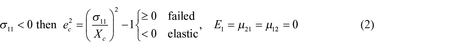
It can be seen from Figure 4 that whether the material property of main cabin is aluminum alloy or composite material, the deformation degree is quite small in the process of impacting. There is only a small concave deformation in impact position, with no element deleted in the whole process of impacting, and the concave deformation of main cabin recovers quickly after fragment rebounds. The residual deformation of aluminum alloy main cabin is very small, whereas there is no residual deformation of composite main cabin. When time is equal to 2.9 ms, rubber fragment starts to contact with the main cabin, and the equivalent stress and deformation are both very small in impact position of the two material properties’ main cabin. When time is equal to 3.4 ms, the maximum equivalent stress occurs in the contact region in the rib of aluminum alloy main cabin, and the maximum equivalent stress is 307 MPa. However, as for composite main cabin, the maximum equivalent stress occurs in the contact region of panel and the maximum equivalent stress is 2600 MPa. When time is equal to 6.2 ms, velocity of rubber fragment decreases to zero and the concave deformation of main cabin reaches to the maximum, but the concave deformation is still quite small. There is obvious stress concentration phenomenon in impact position, middle rib, and middle tension position of stiffener. Since then, rubber fragment begins to rebound with the increase in time, and the concave deformation of these two main cabins recovers well, almost without residual deformation.
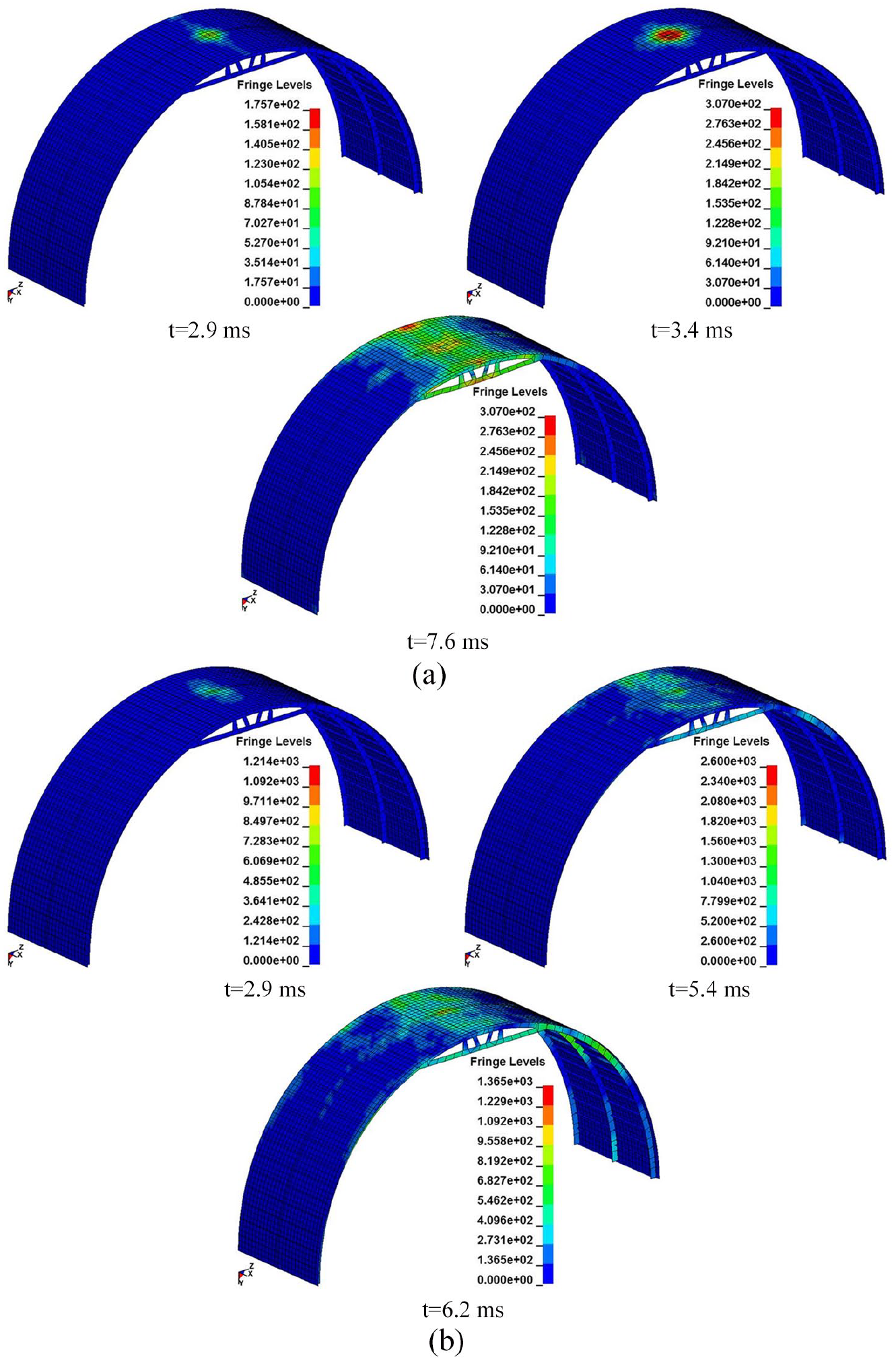
Equivalent stress of main cabin impacted by front tire fragment. (a) Equivalent stress of aluminum alloy main cabin impacted by front tire fragment (t = 2.9, 3.4, and 7.6 ms). (b) Equivalent stress of composite main cabin impacted by front tire fragment (t = 2.9, 5.4, and 6.2 ms).
Dynamic process of main cabin impacted by main tire fragment
The damage degree of main cabin caused by main tire fragment is more serious than that caused by front tire fragment, as shown in Figure 5. The main cabin with the two material properties both generates serious impact deformation, with serious distortion in ribs and stiffeners. When time is equal to 2.9 ms, rubber fragment starts to contact with the main cabin. When time is equal to 3.6 and 4.3 ms, the maximum equivalent stress of the two fuselages occurs in the contact position, tensile region of middle ribs, and stiffeners. The time for rubber fragment’s velocity decreasing to zero is 29 ms when main tire fragment impacts aluminum alloy main cabin, while the time for composite main cabin is 21 ms. Since then, rubber fragment begins to rebound with the increase in time, and the concave deformation of main cabin recovers slowly, but the residual deformation is still very large.
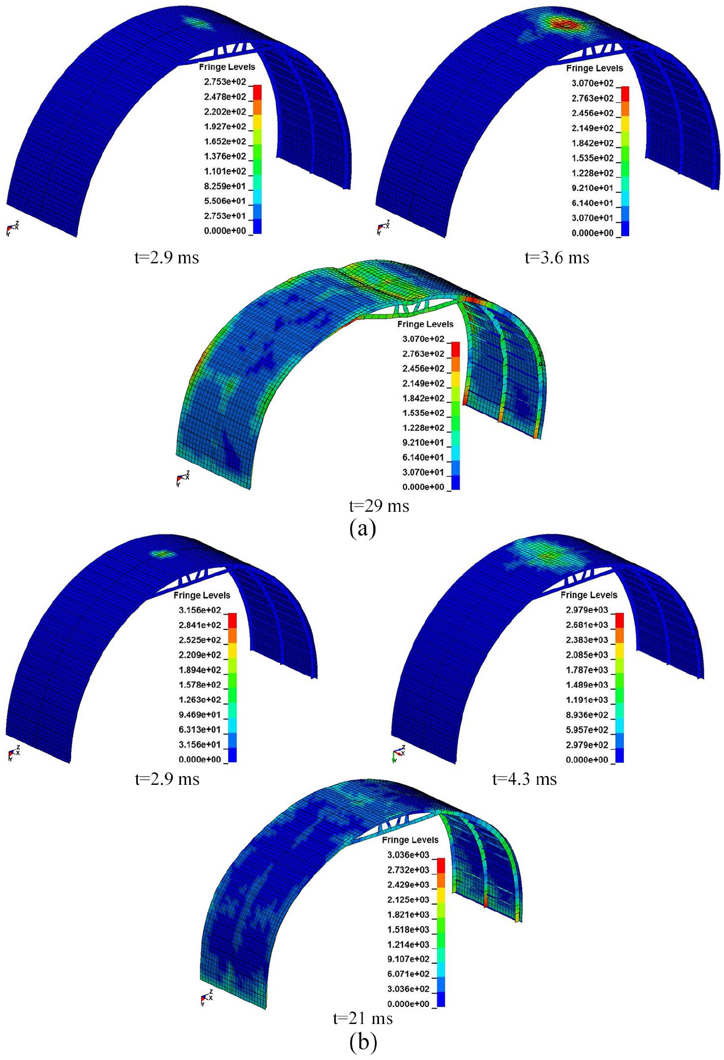
Equivalent stress of main cabin impacted by main tire fragment. (a) Equivalent stress of aluminum alloy main cabin impacted by main tire fragment (t = 2.9, 3.6, and 29 ms). (b) Equivalent stress of composite main cabin impacted by main tire fragment (t = 2.9, 4.3, and 21 ms).
In the above six working conditions, the damage degree of aluminum alloy main cabin caused by main tire fragment is the most serious and the residual deformation is also the largest.
Critical damage velocity
Critical damage velocity is a very important parameter for fuselage when impacted by tire fragment. This parameter determines whether fuselage is in continuous use, damaged, and needs to be repaired or replaced. Fragment velocity has important influence on the impact resistance of fuselage. The higher the impact velocity, the larger impact energy of fragment will be, and the more serious damage of fuselage will occur. When fragment velocity increases to a certain value and elements deletion of front bulkhead and main cabin begins, it is assumed that the fuselage has been damaged. This velocity of fragment is called critical damage velocity of fuselage. Critical damage velocity of fuselage in each working condition is given in Table 5.
Critical damage velocity of fuselage structure for each working condition.

It can be seen from Table 5 that the critical damage velocity of front bulkhead is approximately half of that of main cabin when impacted by front tire fragment. But the critical damage velocity of aluminum alloy fuselage is larger than that of composite fuselage. However, critical damage velocity of aluminum alloy main cabin is less than that of composite main cabin when it is impacted by main tire fragment, which shows that the size of tire fragment has great influence on the impact resistance of fuselage. But the structure type and material property also have great influence on the impact resistance of fuselage. The larger the deformation capacity of fuselage, the better the absorbing energy effect of fuselage and the better impact resistance.
Response of contact pressure, deformation, and energy loss
The influence of rubber fragment impact fuselage on impact resistance not only includes the equivalent stress but also includes the contact pressure, concave deformation in impact position, and energy loss of fragment. These impact responses also reflect the impact resistance of fuselage. The relationship caves of contact pressure and concave deformation at each moment are shown in Figures 6–8, and the calculation results are given in Table 6.
Front bulkhead impacted by front tire fragment: (a) concave deformation and (b) contact pressure.

Main cabin impacted by front tire fragment: (a) concave deformation and (b) contact pressure.

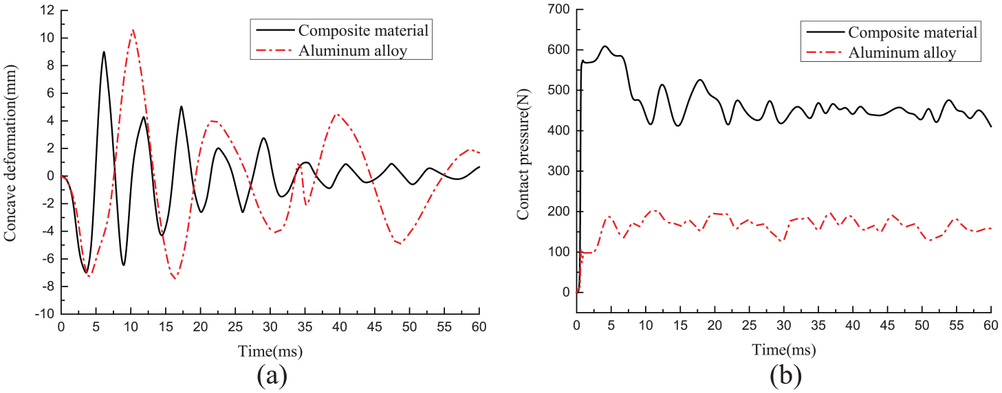
Main cabin impacted by main tire fragment: (a) concave deformation and (b) contact pressure.
Calculation results for all working conditions.

It can be seen from Figures 6–8 that the concave deformation of aluminum alloy front bulkhead is slightly larger than that of composite front bulkhead when impacted by front tire fragment. However, the contact pressure of composite front bulkhead is far larger than that of aluminum alloy front bulkhead. The time required when composite front bulkhead reaches the maximum concave deformation is shorter than that of aluminum alloy front bulkhead. At this moment, the contact pressure of front bulkhead with two material properties also reaches the maximum and there is an oscillation phenomenon near the maximum value. Then, rubber fragment begins to rebound, the concave deformation and contact pressure of front bulkhead decrease gradually, and all of them have a certain degree of oscillation phenomenon, but all tends to balance gradually eventually. Compared with main cabin impacted by front tire fragment, the concave deformation of aluminum alloy main cabin is less than that of composite main cabin. But compared with main cabin impacted by main tire fragment, the concave deformation of aluminum alloy main cabin is larger than that of composite main cabin. The same characteristic is that the contact pressure of composite fuselage is all larger than that of aluminum alloy fuselage. The time required when aluminum alloy main cabin reaches the maximum concave deformation is shorter than that of composite main cabin. Similarly, rubber fragment begins to rebound after the maximum concave deformation reaches, and then, the concave deformation and contact pressure of main cabin decrease gradually and tend to balance gradually eventually.
Table 6 shows that material property also has great influence on the impact resistance of fuselage. When material property of fuselage is composite material, the contact pressure of fuselage is about 3–3.3 times than that of aluminum alloy fuselage. When impacted by front tire fragment, the concave deformation of aluminum alloy fuselage is about 2 times larger than that of composite fuselage. Whereas, the differences of deformation is not significant when they are impacted by front tire fragment. However, the expansion deformation is almost the same when the main cabin was impacted by rubber fragment. The energy loss of rubber fragment is very large in each working condition, and the velocity of rubber fragment almost reduces to zero finally. So, energy dissipation is roughly equal to the initial kinetic energy of rubber fragment.
Conclusion
The dynamic process of front bulkhead and main cabin impacted by tire fragment under bursting mode is studied through numerical simulation. The following conclusions can be obtained through above simulation results:
Composite front bulkhead cannot bear the impact load of front tire fragment at the velocity of 100 m/s and there is only one element deleting in impact position, while aluminum alloy front bulkhead can bear the impact load. Main cabin can bear the impact load of front tire fragment and main tire fragment due to the large deformation captivity, and it can reduce the impact damage through energy absorption by deformation. But the damage degree of aluminum alloy main cabin caused by main tire fragment is the most serious and the residual deformation is also the largest in all working conditions.
Critical damage velocity of front bulkhead is less than that of main cabin, and it is approximately half of that of main cabin under the same fragment. Besides, when impacted by front tire fragment, the critical damage velocity of aluminum alloy fuselage is larger than that of composite fuselage, while the critical damage velocity of aluminum alloy main cabin is less than that of composite main cabin when impacted by main tire fragment.
The maximum contact pressure of composite fuselage is about 3–3.3 times than that of aluminum alloy fuselage. The difference in concave deformation is not significant when impacted by front tire fragment, but the concave deformation of aluminum alloy main cabin is about 2 times larger than that of composite main cabin when impacted by main tire fragment. Finally, the energy loss of rubber fragment is very large in each working condition, and the velocity of rubber fragment almost reduces to zero.
Footnotes
Declaration of conflicting interests
The author(s) declared no potential conflicts of interest with respect to the research, authorship, and/or publication of this article.
Funding
The author(s) disclosed receipt of the following financial support for the research, authorship, and/or publication of this article: This study was supported by the National Natural Science Foundation of China (No. 51875463) and Natural Science Basic Research Plan in Shaanxi Province of China (No. 2018JM1001).