
Abstract
Glass fiber-reinforced plastics (GFRP) based on polymer materials are widely used in lightweight impac-resistant structure design. In the process of design and development, it is very important to clarify the mechanical behavior under dynamic load to improve the product performance. Therefore, in this paper, Quasi-stati and dynamic compression behaviors of unidirectional continuous glass fiber-reinforced vinyl ester (GF/VE) composites with five kinds of fiber contents in the fiber direction were measured by an electro-hydraulic servo experiment system and a split Hopkinson pressure bar, and damage evolution of the material is analyzed by observing the microstructure of the cross section of the material. Results show that: The content of glass fiber affects the wettability between fiber and matrix, and the failure mechanism of material at high strain rate; Under quasi-static conditions, higher glass fiber content yields greater failure strength; Under dynamic conditions, as glass fiber content increases, toughness decreases, and the peak stress first increases and then decreases. Finally, the nonlinear viscoelastic constitutive model with damage evolution is derived, which can be used to predict the impact resistance of new composite structures in the product development and design stage and reduce the development cycle.
Keywords
Introduction
Glass fiber-reinforced plastics (GFRP) is a resin matrix composite material that uses glass fiber and its products as reinforcement materials. 1 Compared with metallic materials, GFRP has the advantages of a low friction coefficient, good fracture toughness, superior specific energy (energy per kilogram) absorption performance, and an extremely high strength to stiffness weight ratio.2–5 GFRP is currently the largest producing and the most widely used composite material worldwide, and it is widely used in lightweight and impact resistant structure design (e.g. automobile bumper and front longitudinal beam). During the application process, materials/components are inevitably affected by static and dynamic loads and high and low temperature environments, 4 Given the inhomogeneity of the GFRP structure, it has anisotropy and low interlaminar shear modulus in mechanical properties.6,7 Research on mechanical properties of GFRP still needs to be developed due to many influencing factors.
In recent years, researchers have examined the static and dynamic mechanical properties of GFRP by using different preparation methods and varying compositions with the universal experimenting machine, a split Hopkinson pressure bar (SHPB) and other experimental devices to effectively describe the mechanical behavior of GFRP under different loads. A high-speed camera, 8 scanning electron microscopy (SEM), 9 micro computed tomography10,11 high/low-temperature environment box,12,13 digital image (DIC) technology,14,15 and pulse shaping technology 16 have also been used to analyse impact deformation, microstructure, damage evolution and failure mode of materials. The results show that the strain rate effect appears in different degrees when the preparation method or composition ratio of GFRP is changed. Temperature also has varying effects on the stress–strain curve of materials under different loading conditions. For example, the following are some of the effects observed: The ultimate tensile stress of glass fiber epoxy material in a quasi-static state depends only on the strain rate, whereas the modulus of elasticity depends on temperature 4 ; For fabric reinforced geopolymer composites, fiber pull out delays the impact propagation 10 ; The impact response of GFRP structures can be accurately predicted by using the strain rate-dependent mechanical behavior of glass fiber polypropylene material compared with those of quasi-static properties 17 ; The damage modes of unidirectional e-glass-reinforced epoxy laminates differ under varying strain rates, resulting in the change in damage degree and temperature, with a maximum damage temperature of more than 219 °C 18 ; Three-dimensional orthogonal woven GFRP shows obvious anisotropy under quasi-static or dynamic loading, and strain rate sensitivity differs under varying loading directions 19 ; Stitch reinforcement can increase resistance in comparison with the standard composite, the existence of Z-fibers made the required fracture energy for crack propagation increased. Stitching does not improve the damage initiation strength but significantly prolongs the duration of the crack propagation phase 20 ; Compared with two-dimensional, three-dimensional woven composites exhibit an increase in strength for both: in-plane and out-of-plane tests 21 ; For glass fiber-braided laminates, the high strain rate and specimen geometry significantly affect the dynamic compressive strength: fiber has a greater effect on strain rate sensitivity than matrix, and damage growth and failure propagation mode also depend on the strain rate22,23; For polycarbonate samples with varying glass fiber contents prepared by injection molding, with increased glass fiber content, the tensile and bending strength of material increased and its impact strength first decreases and then increases 24 ; For the polyester resin matrix, the dynamic parameters of it depended strongly on strain rate due to the visco-plastic effect and the failure modes of the polymer. 25
These studies provide effective support for the design and development of GFRP; however, there are still some problems remain to be solved for unidirectional continuous GFRP.(1) The mechanical behavior and failure process analysis of unidirectional continuous GFRP under high strain rate are complicated due to multi-scale and multi-level defects. The effects of material defects, fiber debonding and matrix cracking on the macroscopic mechanical behavior of GFRP need to be further studied; (2) the unidirectional continuous GFRP under dynamic load will produce a variety of damage forms, and the various damage forms interact with each other, and the failure process is more complex. There is still a lot of research space for the generation and propagation of these damages; (3) there are many researches on the damage constitutive model of GFRP laminates, but there is little research on the combination of dynamic constitutive model and damage evolution of unidirectional continuous GFRP laminates.
In summary, unidirectional continuous GFRP remains to be investigated for static and dynamic mechanical behavior, failure forms, microstructure damage evolution and constitutive model at high strain rate. In particular, the testing and characterization of compressive mechanical behavior at different strain rates is particularly important. In the paper, dynamic and static compression behavior of unidirectional continuous GF/VE was made a study based on the electro-hydraulic servo experimental system and the Hopkinson pressure bar experimental device, and by the use of the method of combining experimental research and theoretical analysis. The fracture morphology of the failure specimen was observed by SEM and the relationship between failure strength and strain rate is illustrated in terms of energy absorption, in addition, based on ZWT constitutive model, a constitutive model with damage factor is constructed.The research ideas and experimental results of this paper can provide a basis for the design, preparation and application of the lightweight impact-resistant structure of glass fiber-reinforced materials.
Materials and methods
Materials and specimen
Vinyl ester resin (VE) has faster wetting ability, better bonding strength and better impact resistance than ordinary polyester resin. 26 It also costs less than epoxy resin, making it the preferred GFRP substrate in impact-related fields. 22 The experimental material in this study was made by Dongguan Xinyi composite Co., Ltd. using a horizontal continuous pultrusion process. 27 Five types of GF/VE profiles (55%, 60%, 65%, 70%, and 75%) (It’s known by market research that when the glass fiber mass fraction is in the range of 55% to 75%, it almost includes the most common GF/VE materials on the market, all of which are often used in lightweight and impact-resistant product design, such as automobile bumper, building base material, sports equipment, electronic components, etc.) were prepared by changing the fiber to matrix ratio. The glass fiber consisted of 386t E-glass direct roving (linear density is 2400 tex, fiber diameter is 17 μm) produced by Jushi Group Co., Ltd. Bisphenol A epoxy vinyl ester resin was used as the matrix. The resin was prepared by reacting epoxy resin and methacrylic acid and diluting the mixture with styrene. The glass fiber yarn surface was coated with a silalkyl wetting agent, immersed in the matrix solution, filled with a proper amount of hydrous magnesium silicate, molded using a heating forming mold, solidified in the mold, and processed into a GF/VE profile with a diameter of Φ12 mm under the action of a traction platform. Figure 1 shows the processing diagram. The fibers of the unidirectional continuous fiber-reinforced material were distributed along the axial direction of material.

GF/VE processing flow.
On the basis of the different loading characteristics in the quasi-static and dynamic compression experiments, GF/VE profiles were machined into two sizes of cylindrical specimens: Φ12 mm × 30 mm (quasi-static uniaxial compression experiment based on GB/T 1448–2005) and Φ12 mm × 5 mm (dynamic compression experiment). Both ends of each specimen were ground to ensure that non-parallelism was less than 0.1% of the height of specimen (Figure 2). The specimens were placed in a 50°C incubator for 24 h to eliminate residual stress.
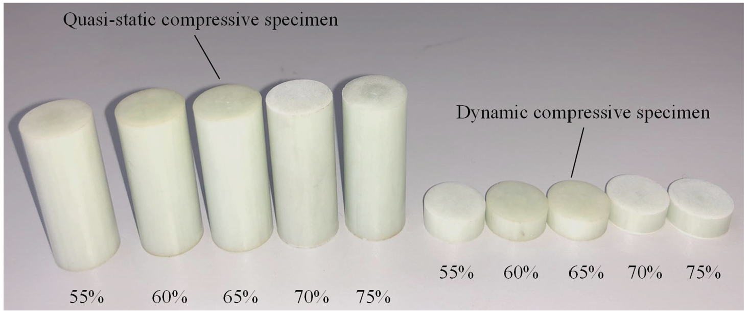
Specimens with different glass fiber mass fractions.
Experimental process
Quasi-static uniaxial compression experiment
We conducted the quasi-static compression experiment on GF/VE specimens (Φ12 mm × 30 mm) with five different glass fiber mass fractions using the MTS landmark 370.5 electro-hydraulic servo experimental system (Produced by MTS industrial systems Co., Ltd) under a room temperature environment (25°C). The specimen is fixed in the center of the base and the bottom head, and the two ends of the specimen are coated with lubricant to reduce the friction between the specimen and the chuck, so that the specimen is approximately in a unidirectional stress state. In order to ensure the accuracy of the experimental results, an extensometer was added to the equipment, and the displacement control mode was used for testing (Figure 3). In accordance with specimen size, the loading speed of the chuck was 0.015 mm/s and the control strain rate was 5 × 10⁻⁴s−1. More than three groups of effective experiments were repeated for each specimen to ensure data accuracy.
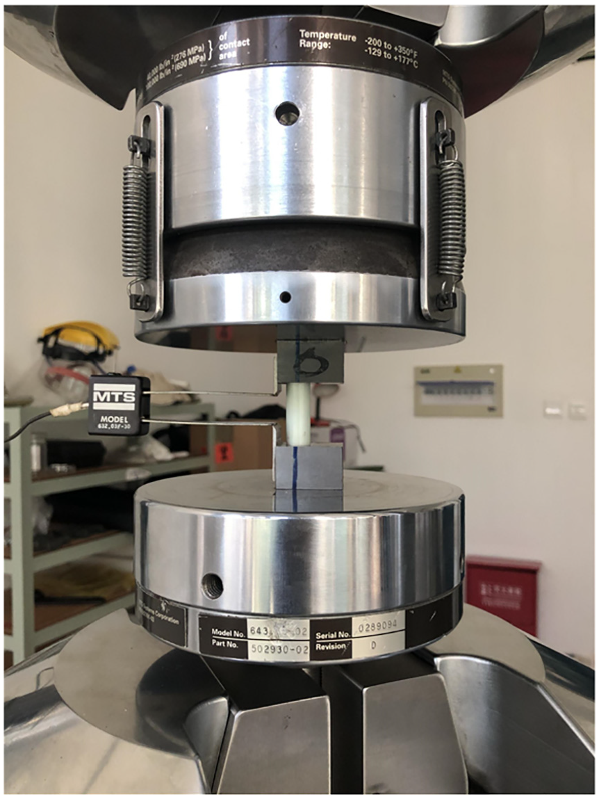
Specimen clamping of quasi-static experimental.
Dynamic compression experiment
The dynamic compression experiment of GF/VE specimens with five glass fiber mass fractions was carried out using a SHPB system (Produced by Luoyang liwei techoogy Co., Ltd) with a 14.5 mm diameter. The system consisted of a pressure bar device, a measuring device, and a data device. The pressure bar device mainly consisted of an impact bar (bullet), incidence bar, transmission bar and absorber bar (damper). The measuring device consisted of a laser to measure bullet speed and a resistance strain gage to record incident signal, reflected signal and transmitted signal. A schematic of the SHPB system is shown in Figure 4.
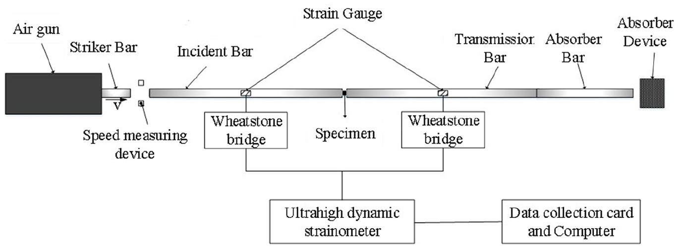
Schematic of SHPB experimental device.
To match the impedance resistance of specimen material, the compression bar devices selected in the experiment were all made of steel alloy with a Young’ s modulus E of 210 GPa, density of 7.83 g/cm3, and elastic wave velocity of approximately 5189 m/s. The length of bullet was 200 mm and the length of both the incident bar and transmission bar was 1000 mm, The length of the absorber bar was 300 mm. The metal strain gage in the measuring device was symmetrically attached to the centers of the incident bar and transmission bar. In the experimental process, the GF/VE cylindrical specimen was clamped between the incident bar and transmission bar, The contact interface between the specimen and the two bars was evenly coated with a thin layer of viscous lubricating oil to reduce friction between the specimen and the compression bar device and ensure that the yield stress of the specimen was strengthened d by the strain rate rather than by the friction effect. Using the constant strain rate loading method in the dynamic compression experiment, the impact velocity of bullet was adjusted, and the pulse signals of specimen under different strain rates were obtained through the measurement system. To ensure data reliability, specimens with different glass fiber mass fractions must be experimented more than four times under varying strain rates.
During the dynamic compression experiment, the material shall meet the stress uniformity 28 :

The strain rate, strain and stress can be expressed as follows:
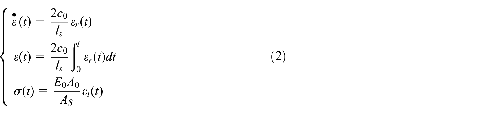
Where
Results
GF/VE quasi-static experiment results and analysis
During the experiment, no obvious changes were observed before the compression failure of the GF/VE specimens. With increased loading, the specimens suddenly experienced brittle failure, which was accompanied with noise. The dislocation occurred in the plane at a 45° angle to the loading axis, and the fracture occurred along the loading direction. When the GF/VE specimen bore a large compressive stress, the resin and glass fiber will also bore a large transverse tensile stress, and the weak point of poor bonding between resin and glass fiber caused fiber peeling and local fiber yield. As the stress continued to increase, the fiber yield led to resin relaxation and softening, resulting in dislocation, Fiber peeling continued to expand to the end face of the specimen. Finally, longitudinal splitting occurred Figure 5 shows a typical failed specimen.

Failed specimen showing dislocation and longitudinal splitting.
The stress–strain curve of GF/VE with five glass fiber mass fractions (55%, 60%, 65%, 70% and 75%) at a strain rate of 5 × 10⁻⁴s−1 is shown in Figure 6. The following findings were drawn from the analysis:
Under the action of quasi-static load, the specimen directly entered the elastic section. Prior to reaching the maximum compressive strength, the stress–strain curve basically maintained a linear relationship, with no obvious yield characteristic and plastic deformation. When the maximum compressive strength was achieved, brittle failure occurred in the specimen.
The specimens showed good homogeneity, and the stress–strain curves of GF/VE with five kinds of glass fiber mass fractions basically showed the same change trend.
The elastic modulus and the maximum compressive strength of GF/VE increase with the increase in the glass fiber mass fraction. The maximum compressive stress of GF/VE with five kinds of glass fiber mass fraction was 408.67 MPa, 416.44 MPa, 432.36 MPa, 436.39 MPa, and 447.07 MPa, respectively. The mass fraction of glass fiber is increased by 20 %, and the compressive strength of the material is increased by 9.4 %.
The maximum strain of GF/VE decreased with the increase in the glass fiber mass fraction. The maximum strain of GF/VE with five kinds of glass fiber mass fraction (from small to large) was 1.445%, 1.439%, 1.386%, 1.357%, and 1.289%, respectively. The glass fiber quality is improved by 20%, and the maximum strain of the material decreased by 0.156%.

Quasi-static stress–strain curves of GF/VE with five different glass fiber mass fractions (55%, 60%, 65%, 70%, and 75%).
GF/VE dynamic experiment results and analysis
The stress–strain curves of GF/VE with different glass fiber mass fractions at high strain rate were obtained by processing the experimental data of SHPB. These curves were then compared with the stress–strain curve of the quasi-static experiment, and the results are shown in Figure 7. The peak stress diagram of different curves is shown in Figure 8.

Dynamic stress–strain curves of GF/VE with five different glass fiber mass fractions. Stress–strain curves for different strain rates (1100–1900 s−1) can be compared with the curve of the quasi-static experiment (black line). (a) 55%. (b) 60%. (c) 65%. (d) 70%. (e) 75%.

Peak stress curves of GF/VE with five different glass fiber mass fractions. Each curve represents a different strain rate.
The following conclusions were drawn from the analysis of Figures 7 and 8:
In the strain rate range of approximately 1100–1900 s−1, the peak stress
When the strain rate was 1100 s−1, the GF/VE specimens were not destroyed, but some fiber cracks and shear failure appeared, Thus, plastic deformation and brittle deformation occur together. When the strain rate increased to 1300 s−1, the GF/VE samples with 55%, 60%, and 65% glass fiber mass fractions were still not completely damaged, but the 70% and 75% glass fiber mass fraction samples were completely damaged, with some powdery and fragmentary glass fibers produced. Therefore, brittle failure occurred. There results showed that with increased glass fiber content, material toughness decreased and brittle failure was likely to occur with increased glass fiber content.
At the same strain rate, as the glass fiber mass fraction increased, the peak stress first increased and then decreased. The peak value of GF/VE with a 65% glass fiber mass fraction was the highest.
The stress–strain curves of these failure-free specimens were in the shape of hysteresis lines, and no residual strain was found in the specimens. The stress–strain curves were sensitive to the strain rate; therefore, the materials exhibited obvious viscoelastic properties.
A typical stress–strain curve of complete failure of a specimen is shown in Figure 9.

Typical stress–strain curve of GF/VE specimen with complete failure.
The stress–strain curve of the completely damaged specimen could be divided into three stages that corresponded to the three stages of specimen failure:
Section AB was the stage of material matrix compaction and hardening, and the curve is concave nonlinear. This section was mainly loaded by the matrix. Considering the inevitable formation of some defects in the preparation process such as micro shrinkage cavities and micro cracks, some defects in the matrix collapsed when the specimen first entered the compaction stage under high strain rate loading.
Section BC was the elastic stage and the curve was basically linear. The matrix and the glass fiber were loaded together, Micro cracks occurred between the fiber and matrix and expanded with increased stress. If unloaded during the elastic stage, the specimen can recover automatically, with the crack between the fiber and matrix closing and almost no residual strain.
Section CD was the softening yield. The yield point was at point C, and the curve was concave nonlinear. When stress was greater than that at point C, elastic deformation and brittle deformation occurred simultaneously. The cracking degree of the matrix and fiber increased continuously and presented the characteristics of shear failure. If unloaded during this stage, the specimen could not be recovered.
Using a GF/VE sample with a 65% glass fiber mass fraction as an example, the typical failure morphology under different strain rates is shown in Figure 10.
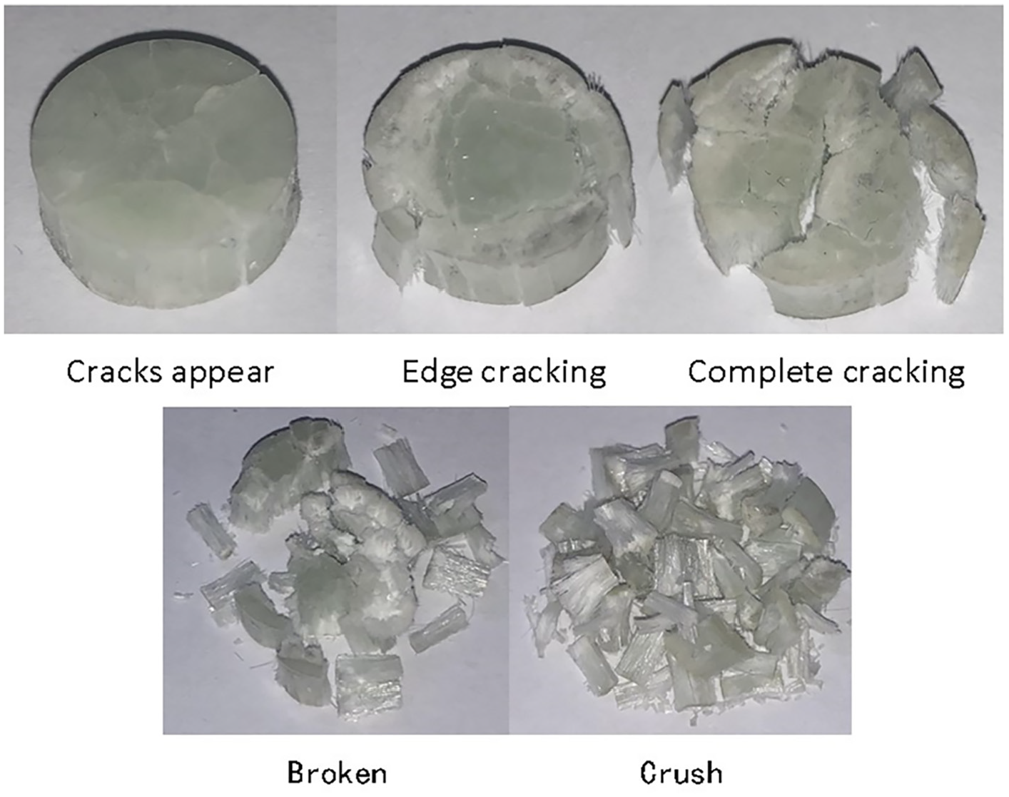
Typical failure morphology of GF/VE (65% glass fiber mass fraction).
In the strain rate range of 1100–1900 s−1, as the loading strain rate increased, the failure morphology of specimen could be divided into cracks appearing, edge cracking, complete cracking, broken, and crushed. Moreover, the failure modes of various morphologies were not instantaneous but the joint evolution of various damage modes belonging to the dynamic response process. The specimen’s failure degree increased with increased loading strain rate, indicating that GF/VE was a strain rate-sensitive material.
Analysis of micro morphology of GF/VE section
To further understand the compression failure mechanism of GF/VE with different glass fiber mass fractions under high strain rates, we investigated cross sections of GF/VE with 55%, 65%, and 75% glass fiber mass fractions under strain rates of 1300 and 1900 s−1 was investigated. The selected samples were treated with gold evaporation, and the section morphology was observed using SEM (Zeiss EV018), as shown in Figure 11.

Micro morphology of cross sections of GF/VE with different glass fiber mass fractions. The cross sections used glass fiber mass fractions of 55%, 65%, and 75% and strain rates of 1300 and 1900 s−1. (a) 55%/1300 s−1. (b) 55%/1900 s−11. (c) 65%/1300 s−1. (d) 65%/1900 s−1. (e) 75%/1300 s−1. (f) 75%/1900 s−1.
A comparison of the micro morphologies of GF/VE with the same glass fiber mass fractions under different strain rates revealed obvious differences. With increased strain rate, the damage of the matrix was more serious, fiber debonding became obvious and many fibers were broken. When the strain rate was 1300 s−1, the observed cross section was relatively flat; when the strain rate was 1900 s−1, the cross section was uneven. Thus, different loading conditions changed the crack growth mode of specimens and caused different damage evolution phenomena. When the strain rate was 1300 s−1, a microcrack had a relatively long time to propagate, When the strain rate was 1300 s−1, a microcrack had a relatively long time to propagate, indicating it had sufficient time to expand and combine into a single macro crack. Thus, the cross section was relatively flat. By contrast, when the strain rate was approximately 1900 s−1, microcrack propagation and combination time was relatively short, Numerous microcracks grew independently in different directions and could not expand and combine into a single macro crack, resulting in the section of the experiment piece being uneven and more thoroughly broken. Given that the energy absorbed as microcracks grow into main cracks and finally broke was lower than that absorbed in when microcracks grew independently and finally broke, high strain rates yielded high failure strength of GF/VE when the glass fibers content of the material was held constant.
At a strain rate of 1300 s−1, the GF/VE section with a glass fiber mass fraction of 55% (Figure 11(a)) had less fiber attached, most of which were broken fibers, with a large amount of fiber shear separation, leaving additional fiber grooves in the matrix. The GF/VE section with glass fiber content of 65% (Figure 11(c)) showed partial fiber shear separation, some of which were broken, and the fiber surface was fully attached by the matrix. For the 75% glass fiber mass fraction GF/VE (Figure 11(e), few broken fibers and fiber adherent matrix and a smooth surface were observed. At a strain rate of 1900 s−1, the 55% mass fraction GF/VE cross section (Figure 11(b)) showed fiber fracture and local fiber fragmentation. The 65% mass fraction cross section (Figure 11(d)) showed relatively more matrix on the fiber surface, with a relatively uniform fiber distribution. The 75% mass fraction GF/VE specimen (Figure 11(e)) showed a large amount of fiber debonding, and the degree of cracking between fiber and matrix was relatively serious.
The different glass fiber mass fractions changed the infiltration degree of the fiber and matrix, as well as the failure mechanism of the composite under high strain rates. The GF/VE fiber with a 55% glass fiber mass fraction had a lower stress bearing capacity. The added fiber cut off the continuous matrix, thereby facilitating crack propagation, the uneven distribution of the fiber led to fiber breakage in areas with more fibers and fiber detachment and matrix damage in areas with fewer fibers when the material was loaded with a high strain rate. Therefore, the impact resistance of the 55% glass fiber mass fraction GF/VE sample, which was weaker than the other glass fiber mass fractions studied in this paper, and 65% mass fraction GF/VE fibers could be evenly distributed in the matrix. Although the continuous matrix was cut off, the combination between the fiber and the matrix was good. When the specimen was loaded with a high strain rate, fiber deformation was limited by the matrix, and the fiber prevented the damage evolution of the matrix. The fiber and matrix restricted each other, thereby, strengthening the mechanical of the composite. The 75% glass fiber mass fraction GF/VE had a low vinyl ester matrix content, meaning some fibers could not fully infiltrate, which led to some weak interfaces in the material. When loaded with a high strain rate, the fibers at the interface easily broke away from the matrix and local layer and fiber cracking appeared. These changes reduced the strengthening effect of the composite, making it prone to brittle failure.
ZWT constitutive model of GF/VE with damage evolution
A series of experimental studies on many typical engineering plastics (epoxy resin, ABS, PMMA and PC) 30 showed that the constitutive behavior of typical polymers (including thermosetting and thermoplastic) under high strain rate loading can be described by the ZWT constitutive model, which consisted of a nonlinear spring unit and two Maxwell units. Figure 12 shows a schematic of the ZWT constitutive model. Equations (3) and (4) are constitutive relations.


where

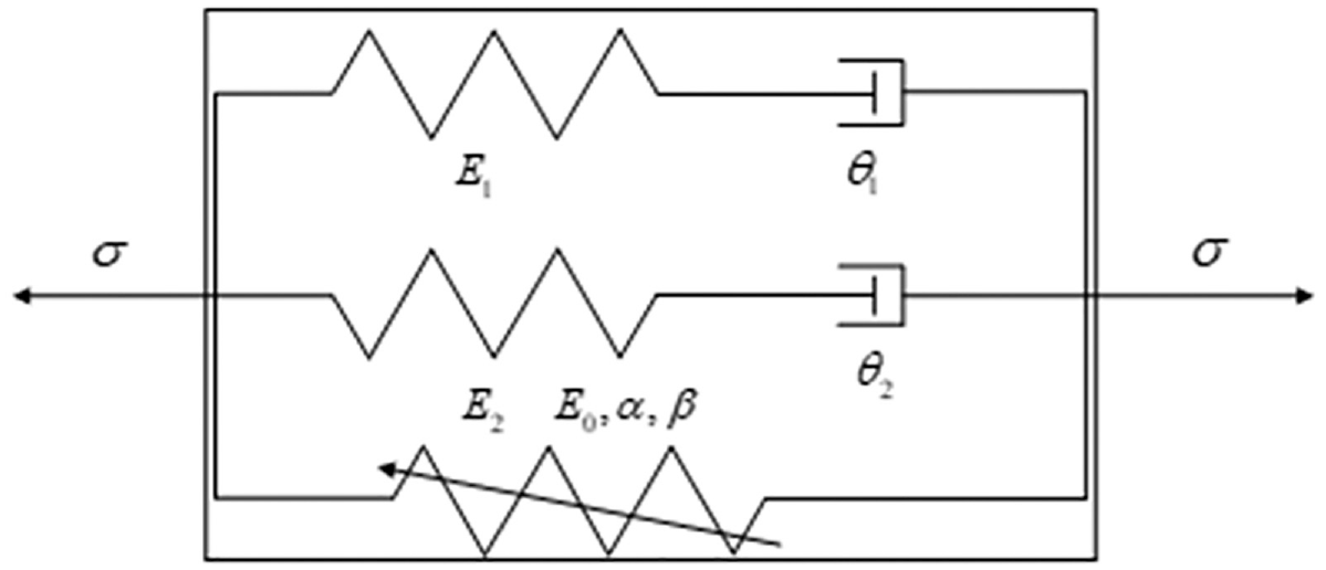
Schematic of the ZWT model.
Given that the loading rate of the SHPB dynamic test can be regarded as a constant strain rate loading before specimen failure, the above formula can be rewritten as follows:

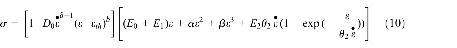
When a GF/VE composite was loaded at a high strain rate, microcracks will appear and the number of microcracks will increased with increases in deformation and strain rate. Crack generation and evolution will inevitably weakened the ability of material to resist deformation. The constitutive model of ZWT could only describe viscoelastic characteristics and can not express mechanical characteristics of the material under yield or damage. Therefore, the damage evolution process could be regarded as a stress-induced thermal activation process, and the damage variable (damage factor) defined by Kachanov can be introduced as:

where
Therefore, the ZWT equation with damage evolution can be expressed as follows:

In general, the relationship between damage and strain is nonlinear:

Here,
Given that the unidirectional continuous GF/VE prepared by a pultrusion process inevitably showed some initial microcracks and other defects, the material was in the damage evolution stage from initial compaction and hardening to specimen failure under high strain rate loading, and thus the strain threshold
To verify the model’s accuracy, the experimental data for GF/VE materials with 60% and 70% glass fiber mass fractions before reaching the ultimate stress were fitted. The corresponding fitting parameters of the two types of GF/VE under five strain rate loadings are shown in Table 1, and a comparison between the fitting curve and the test curve is shown in Figure 13.
Parameter value of ZWT model fitting with damage evolution.


ZWT fitting curve with damage evolution and experiment curve. (a) 60%. (b) 70%.
In summary, the rate correlation index δ value in the simulation parameter was less than 1, meaning that the failure strain of unidirectional continuous GF/VE increases as the loading strain rate increased. In other words, the material demonstrated an impact toughening phenomenon. R2 of the fitting data was more than 99.9% and the fitting curve showed a high degree of agreement with the test curve before reaching the ultimate stress, which demonstrates that the ZWT constitutive model with damage evolution could clearly describe the compaction hardening stage, elastic stage, and softening yield stage of unidirectional continuous GF/VE composites prepared using a pultrusion process under a high strain rate. Thus, there results are accurate.
Conclusions
We tested the compression mechanical properties of GF/VE with different glass fiber mass fractions at low and high strain rates using an MTS landmark 370.5 electro-hydraulic servo experimental system and an SHPB experimental device. We then observed the failure forms. The GF/VE compression failure mechanism at high strain rates was observed from a microscopic point of view, and a ZWT constitutive model with damage evolution was constructed. The following conclusions were drawn:
Under quasi-static compression, the stress–strain curve of GF/VE showed good homogeneity and the material directly entered the elastic section. Before reaching the maximum compressive strength, the linear relationship was basically maintained; however, brittle failure occurred instantly once the maximum compressive strength was reached. High glass fiber content in GF/VE yielded a high modulus of elasticity and maximum compressive strength, a small failure strain and low toughness.
Under dynamic compression, GF/VE materials showed an obvious strain rate correlation. The typical stress–strain curves were divided into three stages: a compaction hardening stage, an elastic stage and a softening yield stage. With an increased strain rate, compressive strength increased. The material’s failure morphology was divided into cracks appearing, edge cracking, complete cracking, broken, and crushed. At the same strain rate, compressive strength first increases and then decreases with increased glass fiber content, and the compressive strength of GF/VE with a 65% glass fiber mass fraction was the largest.
With increased strain rate, the damage to the matrix worsened, fiber debonding became obvious, and many fibers broke. The failure strength of GF/VE materials with the same glass fiber content increased as the strain rate increased. Glass fiber mass fraction differences changed the infiltration degree of fiber and vinyl matrix and altered the material’s failure mechanism under high strain rates.
The ZWT constitutive model with damage evolution could be used to better describe the compaction hardening stage, elastic stage and softening yield stage of unidirectional continuous GF/VE composites prepared by a pultrusion process and predict the experimental results.
In the design and development of glass fiber-reinforced plastics, these experimental results and the constitutive model with damage factor are the key to clarifying the mechanical behavior of materials under impact loading and improving the performance of impact resistant/lightweight components in the automotive, architecture, aerospace, electronics, and other industries. These factors are very important for material design and development. However, in this paper, the mechanical behavior of GFRP could not be fully reflected by our experimental study of GF/VE with 55% to 75% glass fiber mass fractions under six kinds of strain rates. Some mechanical parameters had no specific value, but an indirect comparison could be made through the stress–strain curve. The starting point of the elastic stage and the position of the yield stage’s starting point under dynamic loading conditions still need further study. In the latter stage, we will study changes in environmental temperature and the mechanical response of materials with different resin matrixes, characterize specific parameter values, clarify the physical meaning, examine the influence of energy transfer transformation on the physical properties of materials during internal damage evolution and build a damage evolution constitutive model with strain rate as the only variable. Doing so will aid help further the design and development of glass fiber-reinforced composite materials by providing a theoretical model and method support.
Footnotes
Appendix
Declaration of conflicting interests
The author(s) declared no potential conflicts of interest with respect to the research, authorship, and/or publication of this article.
Funding
The author(s) disclosed receipt of the following financial support for the research, authorship, and/or publication of this article: Authors thank the Key Natural Science Research Projects of Anhui Higher Education Institutions (Grant No. KJ2016A145), Natural Science Foundation of Anhui Province (Grant No. 1708085ME130), Anhui Education Department Excellent Young Talent Support Project (Grant No. gxyqZD2019057), Open Fund of State Key Laboratory of Vehicle NVH and Safety Technology (Grant No. NVHSKL-201407), and Anhui Province Key Research and Development Project (Grant No. 1804a09020009) for the financial support.