
Abstract
A novel compensation control strategy is proposed to compensate for automatic steering system controller limitations in instability under nonlinear interference condition. In this article, the structure and mechanism of automatic steering system are briefly introduced at first. The nonlinear dynamic models of automatic steering system and vehicle are established, and the interference torque models of automatic steering system caused by different speed are then derived through the mechanism of tire structure. Simulations under different road conditions and different vehicle velocities are then used to validate the influence of nonlinear factors on the automatic steering system. Finally, the compensation controller is designed, and the effectiveness of designed controller has been verified by simulation results, in which the dynamic control effect and tracking accuracy of designed controller have been improved significantly. Finally, the novel controller is designed based on Simulink results, and test results reconfirm the partial performance of controller effectively.
Keywords
Introduction
As one of the important parts of intelligent vehicle system, automatic steering system (ASS) can make intelligent vehicle to accurately track the desired unmanned vehicle trajectory via onboard sensors such as vision system1,2 or the Global Positioning System, 3 which provide feedback signals. The field of automatic steering control system is well established, and the available literature on the topic is vast. To begin this thesis, several of the most common approaches to automatic steering control system will be presented.
Earlier papers that study on automatic steering controller verified the effectiveness of ASS. Zhao et al.4,5 proposed a displacement and force coupling control design for active front steering (AFS) system of vehicle which can improve the cornering stability and maneuverability of the vehicle. Zhang et al. 6 proposed an AFS control strategy based on quantitative feedback theory, and the control system can improve the dynamic response of the vehicle by incorporating feedback from a yaw-rate sensor into the active steering system. Guo et al. 7 designed the automatic steering controller for trajectory tracking of unmanned vehicles using genetic algorithms, and different control algorithms are compared to verify the effectiveness of designed control algorithm. Chaib et al. 8 studied on various steering control strategies by simulations over a test track circuit. Eski and colleagues9,10 present a neural network–based robust control system design for the active steering system based on the simulation contrast results of four control algorithms; the results showed that the proposed neural network–based robust control system had superior performance in adapting to large random disturbances. Gao et al.11,12 studied the coordination control of AFS and ESP (electronic stability program), and the general principle of coordinated control was proposed. There are also some papers13–16 that adapted some other control methods for ASS in unmanned vehicle trajectory tracking.
In recent years, interest in studying the dynamic performance effects and designing stabilizing controllers that account for nonlinear factors in ASS is also increasing with the development of nonlinear research on steering system. Mammar and Koenig 17 investigated the influence of vehicle speed, pavement coefficient, and the steering angle on vehicle yaw rate under phase-plane condition, and the feedback H∞ controller for AFS system is adopted to improve vehicle handling stability. Ghani et al. 18 used sliding mode control strategy to overcome various external coefficients of road frictions on active steering vehicle system. Mohammadi and Saee19,20 presented a variable structure model reference adaptive control strategy for nonlinear steering system. Li and colleagues21,22 study the globally exponential synchronization problem of dynamical networks with nonlinearly coupling function, and the derived sufficient conditions are closely related to the parameters of system dynamics, impulsive gain, impulsive interval, and the proportion of the controlled components.
However, the nonlinear mechanism study of ASS is relatively shallow based on the above researches, especially cannot detailed analysis the difference of interference torque caused by different speed. Besides, the research of ASS control strategy mainly focused on the vehicle stability, steering agility, and some others, and the research on the dynamic control effect of the steering system is less. In this article, the structure of ASS is designed, and the corresponding dynamic model is proposed. The influence of nonlinear factors which compile with the interference torques caused by different speed on the ASS is analyzed, and the compensation control algorithm is then adopted, which can meet the dynamic steering effect and low-speed aligning capacity perfectly under different conditions.
ASS
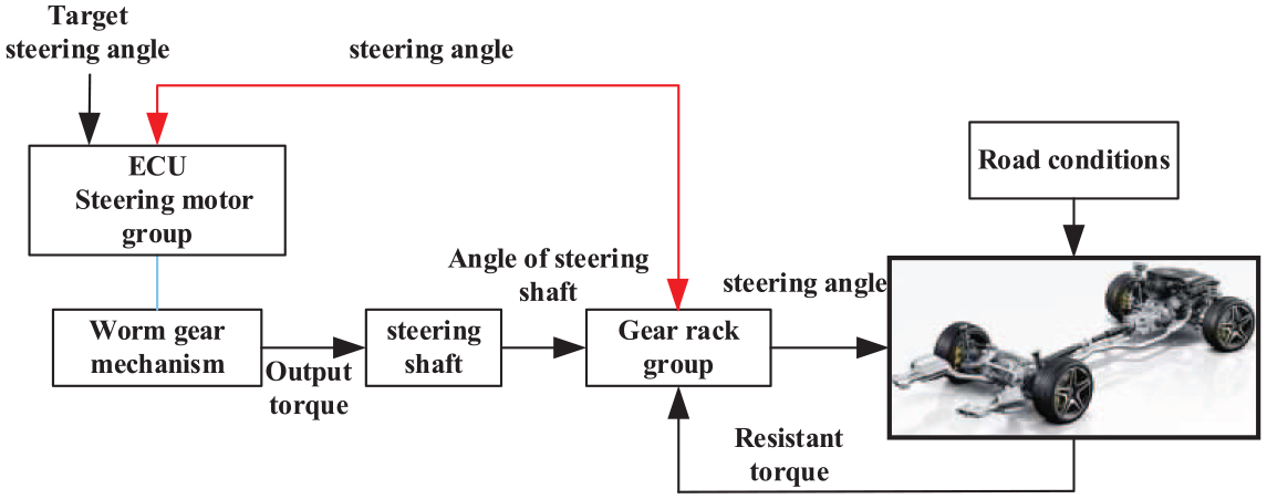
The working principle flowchart of ASS is shown in Figure 1.
Control system flowchart.
Figure 1 shows the design of ASS, which includes electric control unit, steering motor group, worm gear mechanism, steering shaft, gear rack group, angle sensor of steering shaft, angle sensor of tires, and vehicle speed sensor. The working principle of ASS is shown as follows.
Given external signals such as target steering angle, detect output steering angle, and road conditions based on the correlation sensors, the motor current and motor torque of steering motor group will be calculated based on the ECU, and the output torque which is amplified by worm gear mechanism will be fed into steering shaft, and then the steering angle of tire is worked out.
Besides, the flowchart of ASS control strategy is shown in Figure 2, which includes basic steering control, phase compensation control, and steering interference torque compensation control. In this flowchart, the basic steering control strategy uses the proportional–integral–derivative (PID) controller to control the steering angle based on the deviations between target steering angle and detect output steering angle of tires. And phase compensation controller and steering interference torque compensation controller will further improve the accuracy of the steering tracking because of the poor adaptation of constant parameter PID controller.
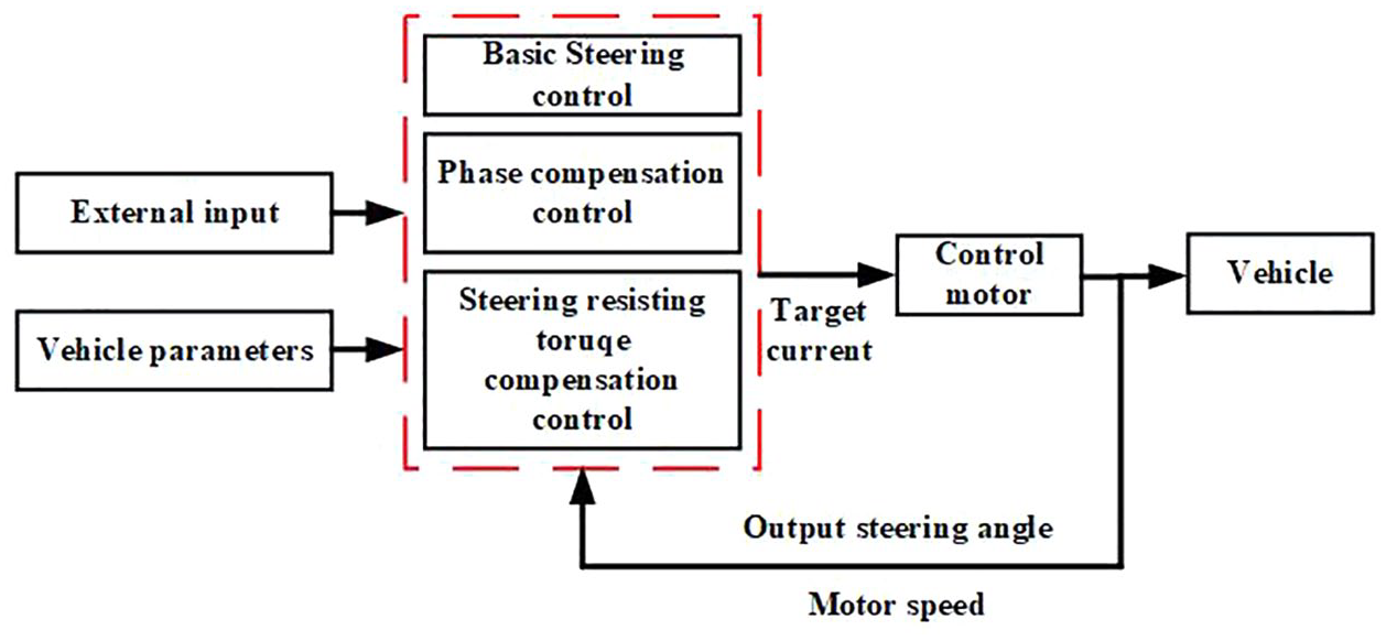
ASS control strategy flowchart.
Modeling
ASS dynamic model
ASS is composed of many mass elements or inertia elements with elastic and damping characteristics and fully considering the characteristics of all components will make the system model very complex and unnecessary. In this article, the influence of steering resisting torque on ASS is studied, and the model of ASS is simplified by the reduced order processing in the premise of not changing the basic structure of the system, and some of the key physical models are equivalent to the mechanical components. The structure of ASS is shown in Figure 3, which combined with steering motor group, steering shaft group, gear rack group, steering resistance moment model, and so on.
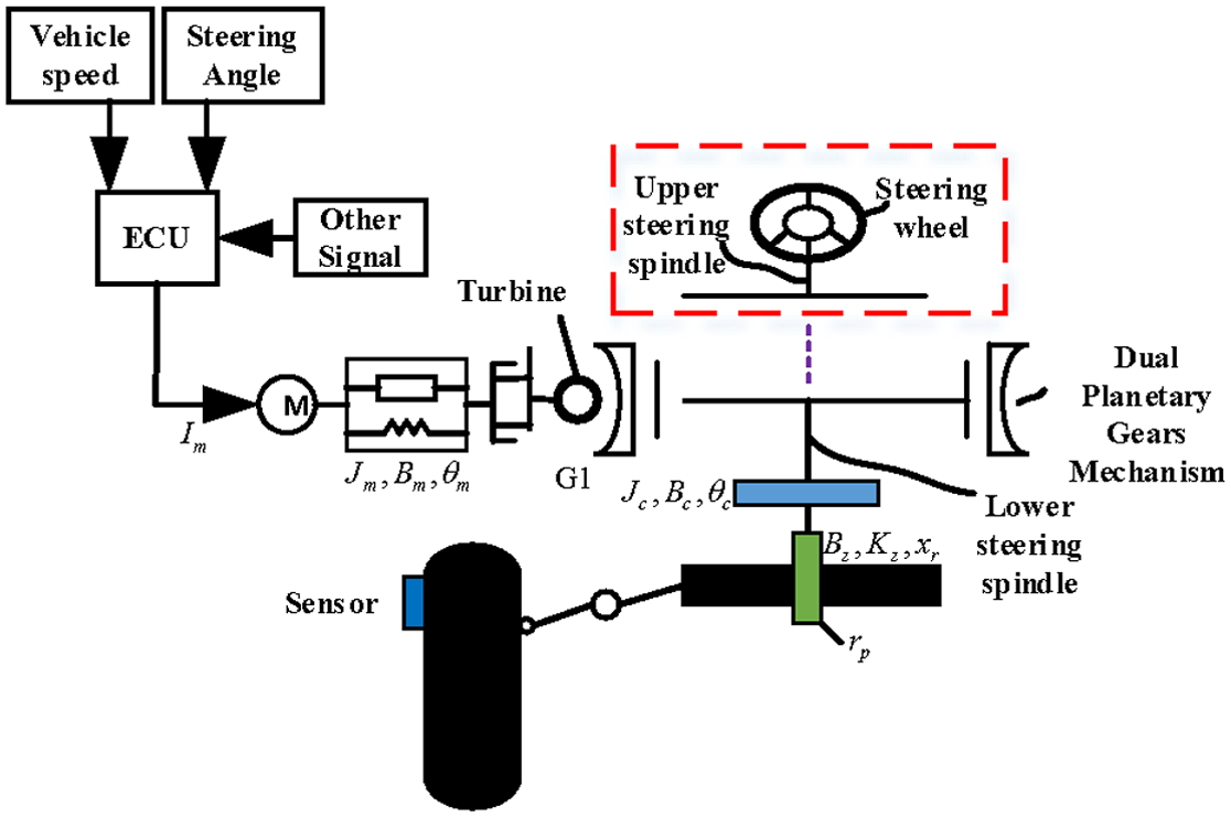
Structure of automatic steering system model.
Ignoring the internal nonlinear factors in ASS, the dynamic model of ASS is expressed in equations (1) to (3)


where

where

where
Vehicle dynamic model
According to the block diagram of the ASS, the vehicle dynamic model is established. Figure 4 shows the 7 degrees of freedom vehicle dynamic model compiling with nonlinear tire model, which can express the complex characteristics of the vehicle system effectively.

Vehicle dynamic model with 7 degrees of freedom.
Ignoring the vertical movement of vehicle, and assuming that lateral acceleration of vehicle is less than 0.4g based on limit rollover condition of linear vehicle model, the 7 degrees of freedom vehicle dynamic model23,24 can be given in equations (6) to (8)


where
Steering resisting torque model
According to the dynamic model of ASS, the only external disturbance is steering resisting torque. To further study the effect of steering resisting torque on ASS, the tire dynamics model is established and the model of the right steering tire is shown in Figure 5.
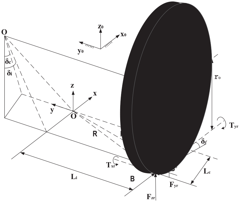
Model of the right steering tire.
Ignoring the force difference between left and right tires and assuming that the axial force of tire is uniform, the steering resisting torque model can be defined as

The steering resistance torque includes the aligning resistance torque and friction resistance torque, and the form of steering resistance torque will be shown differently under different speed conditions. When the vehicle steering is at static condition, the values of tire slip angle and lateral force are zero; the steering resisting force is mainly caused by friction and tire aligning torque based on gravity. The steering resisting torque can be expressed as

where

where
When vehicle runs under 5 km/h, the value of static steering friction resisting torque is zero, and the steering resisting torque is mainly caused by aligning torque; the formula of steering resisting torque is given by

where
And
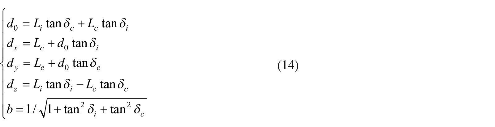
In equation (14),
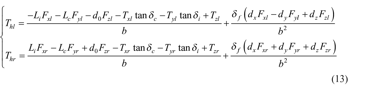
When vehicle runs over 5 km/h, the steering resisting force is mainly caused by tire lateral force, and the formula of steering resisting torque is given as

where t is the distance between tire lateral force action point and center of tire contact, which is obtained as

where
From the above, the formula of steering resisting torque can be expressed as

And the model part parameters are shown in Table 1.
Parameters of ASS.

ASS: automatic steering system.
Analysis
There are different kinds of interference torques (friction torque and aligning torque) in steering system, and also some phase delay between target input and detect output of tire steering angle. To verify the effect on the tire steering angle from different kinds of resistant torques and phase delay, different contrast simulations are carried out under different steering conditions.
Many steering control approaches have been presented to handle the trade-off by the utilization of various control techniques, such as fuzzy control, PID control, neural-network control, gain scheduling control, linear optimal control, adaptive control, and H∞ control, and their combined methods. It should be noted that PID control is a practical alternative for a variety of challenging control applications such as its simple structure, good stability, dependable work, and convenient adjustment. In this article, the difference value between target tire steering angle

where the values of
Effect on the tire steering angle under state conditions
According to the dynamic model of ASS and steering interference torque model in the “Steering resisting torque model” section, the interference forms of steering interference torque on vehicle steering show differently under different speed conditions. When the vehicle steering is at static condition, the response time of ASS will be slowed because of the interference of sliding friction torque and aligning torque between tires and ground, and the steering interference torque also reduces the effect of tire aligning process. Figure 6 shows the output of tire steering angle under state condition; this simulation assumes that the step input of tire target angle is set to 5°, and the tire/road friction coefficient is set to 0, 0.3, 0.5, 0.7, and 0.9.

Effect on the tire steering angle under state condition.
Figure 6 shows the steering angle tracking performance of ASS. According to Figure 6, the peak value of tire output angle is getting lower with the increase of tire/road friction coefficient, and the time to reach a stable process is increased. The results show clearly that the tracking accuracy of tire steering angle is getting worse with the increase of external interference torque because of the poor adaptation of constant parameter PID controller.
In order to further research the effect on the tire steering angle from friction interference torque, two different simulation conditions are used which are shown in Figure 7: Figure 7(a) assumes that the step input of tire target angle is set to 5°, and Figure 7(b) assumes that the square wave input of tire target angle is set to 5°, and the tire/road friction coefficient is set to 0, 0.3, 0.5, 0.7, and 0.9.

Effect on the tire steering angle from different coefficients of sliding friction: (a) step input and (b) aligning input.
Figure 7 shows the steering angle tracking performance of ASS under different inputs. According to Figure 7(a), the output curves of tire steering angle (f = 0.3, f = 0.5, f = 0.7, and f = 0.9) are similar to the corresponding curves in Figure 6, and the gap between first curve (f = 0) and second curve (f = 0.3) is getting smaller due to the lack of aligning torque interference based on gravity. Figure 7(b) shows that the return-to-center performance is getting poor with the increase of tire/road friction coefficient.
Effect on the tire steering angle under low-speed conditions
The effect on the tire steering angle from different coefficients of sliding friction has been shown clearly according to the above simulations in the “Effect on the tire steering angle under state conditions” section, and the effect on the tire steering angle from aligning torque based on gravity is also considered in Figure 8. This simulation assumes that the step input of tire target angle is set to 1°, 3°, and 5° based on equation (12), and the simulation result shows that the value of aligning torque based on gravity is only related to the value of tire steering angle.

Effect on the tire steering angle under low-speed conditions.
Effect on the tire steering angle under high-speed conditions
According to equation (14), the value of aligning torque based on gravity is related to the value of tire steering angle and vehicle speed. To further study the relationship between vehicle speed and tire steering angle, different vehicle speed conditions are considered. The simulation assumes that the step input of tire target angle is set to 5°, and the vehicle velocity is set to 10, 30, 60, and 90 km/h. The simulation results are shown in Figure 9.
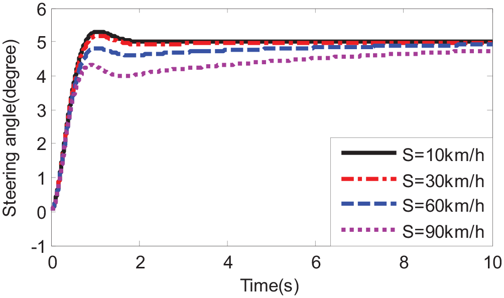
Effect on the tire steering angle under high-speed conditions.
Effect on the tire steering angle with phase delay
There is some phase delay in the processing of ASS controller and actuator, which have great influences on the stability and accuracy of ASS. In this section, the phase delay of ASS actuator is considered, the simulations of ASS under different phase delay and same control parameters are analyzed, the sin-input of tire target angle is set to 5°, and the transformation frequency of target steering angle is set to 0.25 and 1 Hz. The simulation results are shown in Figure 10. Besides, the peak value and phase delay between target angle and output angle are shown in Table 2.

Effect on the tire steering angle from phase delay: (a) 0.25 Hz and (b) 0.1 Hz.
The peak value and phase difference under sin-input condition.
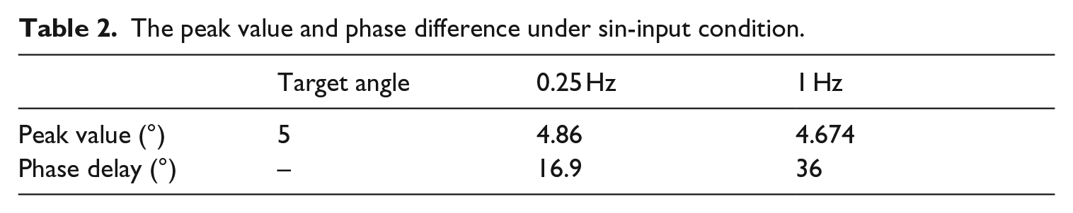
Figure 10 and Table 2 show that the response speed of ASS and the tracking accuracy of basic control system become worse with the increased frequency of target steering angle. The phase gap at 1 Hz is larger than that at 0.25 Hz, which means that there is a great influence on the tracking accuracy and response speed of basic control system from steering angle frequency.
Compensation control
According to the above simulation results and steering interference torque model in the “Steering resisting torque model” section, the response speed and tracking accuracy of ASS are affected obviously by the steering interference torque based on the basic control system. So, it is necessary for ASS to make a compensation control to improve the dynamic steering effect.
Steering interference torque compensation control
The steering interference torque compensation control based on motor speed is expressed as

where
In order to verify the steering interference torque compensation control effect, the simulation contrasts are carried out in Figure 11, and Tables 1 and 2 show the peak value of curves in Figure 11. Figure 11(a) assumes that the step input of tire target angle is set to 5°, and the friction interference torque is set to 0, 100, and 300 N·m. Figure 11(b) assumes that the step input of tire target angle is set to 5°, and the vehicle velocity is set to 10, 30, 60, and 90 km/h. In Figure 11, and S refer to the basic steering controller, and C refers to the steering controller, which compiles with basic steering control and steering interference torque compensation control.

Effect of steering interference torque compensation: (a) pure friction and (b) high speed.
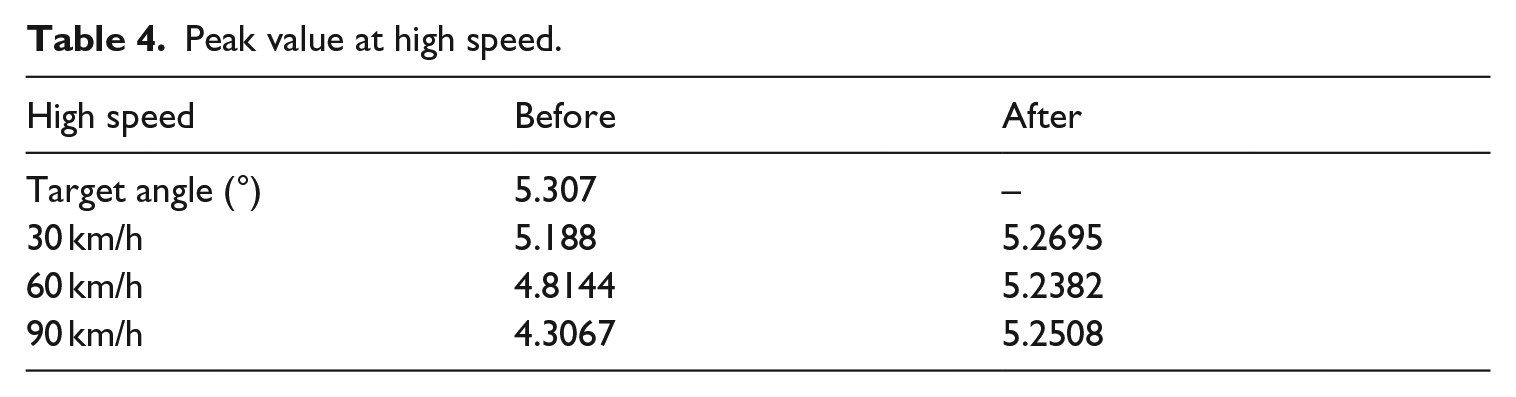
Table 3 shows that the peak values of detect output steering angle are increased by 1.23% and 3.92% for C in comparison with that of S, illustrating that the steering interference torque compensation control algorithm can effectively compensate for the lack of tracking accuracy caused by torque interference. And the simulation results on Table 4 also show clearly that the steering controller which compiles with basic steering control and steering interference torque compensation control has improved the tracking accuracy of tire steering angle. To show clearly about the peak value results on Tables 3 and 4, two bar charts are used which are shown in Figure 12.
Peak value under pure friction interference.

Peak value at high speed.
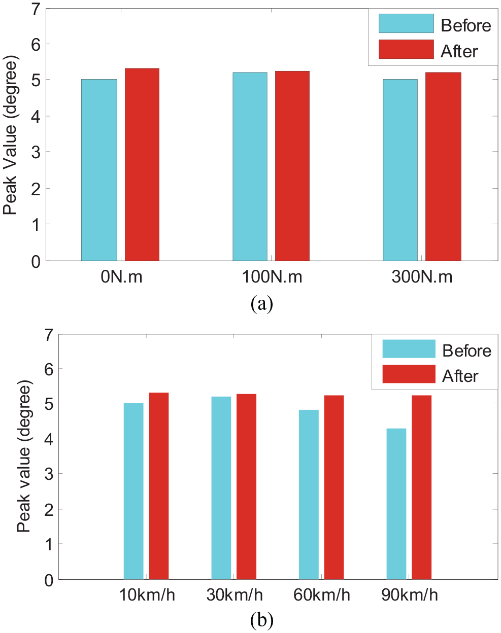
Peak value comparison of steering angle before and after compensation: (a) pure friction and (b) high speed.
Phase compensation control
In order to improve the fast responsiveness of ASS control, the phase advance compensation of tire steering angle sensor signal is carried out, and the phase correction module is adapted as

where
In order to verify the effect of phase compensation control, the simulation contrasts are carried out in Figure 13. The figure assumes that the sin-input of tire target angle is set to 5° without external steering torque interference. The simulation results show obviously that the tracking accuracy and response speed of ASS have been improved after phase compensation, and the phase gap between target tire steering angle and detect output of tire steering angle is small enough, which means the phase compensation control is effective.

Effect of phase compensation: (a) 0.25 Hz and (b) 1 Hz.
Integrated control
According to the above equations, the current after compensation is shown as

In order to verify the effect of integrated control system, the contrast simulation is shown in Figure 14, and the peak value and phase delay between target angle and output angle are shown in Table 5. The simulation assumes that the sin-input of tire target angle is set to 5°, and the vehicle velocity is set to 30, 60, and 90 km/h.

Integrated compensation control.
Peak value and phase delay under sin-input condition.
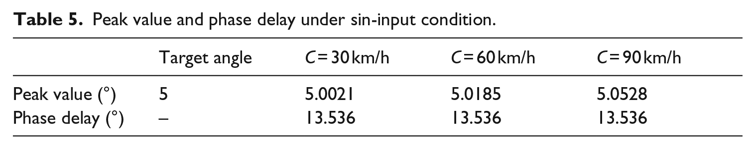
Figure 14 and Table 5 show that the phase gap between target tire steering angle and detect output of tire steering angle is 13.536°, which means it does not vary with the steering interference torque changes. Besides, the peak value of detect tire steering angle varies with the steering interference torque changes and the numerical changes are small. To summarize, the simulation result shows the validity and accuracy of integrated controller. To show clearly about the peak value results in Table 5, a bar chart is used which is shown in Figure 15.

Peak value and phase delay under sin-input condition.
Test
In this section, the controllers (PID controller and designed compensation controller) are developed and installed at hybrid control unit hardware-in-the-loop (HCU-HIL) test bench, and two different conditions are adapted to verify the superiority and effectiveness of designed controller. The ASS-controlled model and controller model are also uploaded in the test bench during the test preparation phase. Figure 16 shows the HCU-HIL test bench.

The HCU-HIL test bench.
To verify the superiority and effectiveness of designed controller, two contrast tests under different conditions are carried out. Figure 17 assumes that the step input of tire target angle is set to 5° without external steering torque interference, and the velocity is set to 30, 60, and 90 km/h. Figure 18 assumes that sin-input of tire target angle is set to 5° with different vehicle velocities. Moreover, S1 and S2 in Figures 17 and 18 refer to the simulation results and test results of designed compensation controller, respectively.

The contrast test under step input at different velocities: (a) 30 km/s, (b) 60 km/h, and (c) 90 km/h.

The contrast test under different steering transformation frequencies: (a) 0.25 Hz and (b) 1 Hz.
The HCU-HIL test results show clearly that the designed controller can meet the design requirements. The test result curves of designed controller are similar to that of simulation, and the results are obviously superior to the PID controller, which effectively verified the effectiveness of designed controller.
Conclusion
This article further researches the influence of nonlinear factors in ASS according to the dynamic models of ASS, vehicle dynamic models, and mechanism of tire structure. The phase delay and the interference torque caused by vehicle velocity are considered in this article. The rationality and feasibility of the designed control system are validated with numerous contrast simulations with different road conditions and vehicle velocity. The obtained results indicate that novel compensation controller effectively compensates the limitation of traditional ASS controller in steering tracking accuracy and dynamic control effect. The different simulation programs are then applied to verify the effectiveness of designed controller. Further study on experimental implementation of the controller through the intelligent vehicle will be conducted in the near future. Further study on experimental implementation of the controller through the HCU-HIL test bench has been conducted in this article, and the test results reconfirm the superiority and effectiveness of designed controller.
Footnotes
Declaration of conflicting interests
The author(s) declared no potential conflicts of interest with respect to the research, authorship, and/or publication of this article.
Funding
The author(s) disclosed receipt of the following financial support for the research, authorship, and/or publication of this article: This work is supported by the program of the National Natural Science Foundation of China (Grant No. U1564201 and Grant No. 51875255), National Natural Science Foundation of Jiangsu Province China (Grant No. JA460005), and the Key Project Plan of Zhenjiang City (Grant No. GY2015029).