
Abstract
Yarns from recycled carbon fibre (rCF) and thermoplastic fibres have shown potential in achieving high mechanical properties in thermoplastic composites. As the thermoplastic fibre component of the yarn melted during the composite manufacturing to form the matrix of the composite, the rCF content of the yarn is equivalent to the rCF content of thermoplastic composites (typically 45–55% by volume). However, in order to use such yarns for thermoset composites from rCF, the yarn must be impregnated with a liquid thermoset resin. To ensure good mechanical properties in thermoset composites, the rCF content in the yarns must be as high as possible. Due to the smooth surface and lack of fibre-to-fibre cohesion, producing yarn or slivers from rCF alone through carding and drawing is highly challenging. As a result, the use of rCF yarns in thermoset composites remains underexplored. This research addresses the knowledge gap by examining the influence of rCF yarn structures on tensile and impact properties of composites. Two yarns were developed using friction and wrap spinning techniques, where a core of rCF is wrapped with thermoplastic filaments or fibres (<10 wt%) to achieve an rCF content of >90 wt%. The developed yarns were impregnated with epoxy resin using the resin transfer moulding technique to produce unidirectional composites. The investigations show that while the compactness, hairiness and processability of the yarn are significantly affected by differences in yarn structure, the tensile and impact properties of the composites remain comparable.
Keywords
Introduction
Due to strict regulations on composite disposal and the restricted landfilling of carbon fibre (CF) materials (EU Directive 1999/31/EC), combined with the high cost and energy demand of virgin CF production (∼39 MJ/kg), the reuse of CF waste and recycled carbon fibre (rCF) presents a promising solution for waste management and resource sustainability.1–5 Industrial applications already utilize rCF in nonwovens6,7 and injection-moulded structures8,9 for the manufacturing of carbon fibre reinforced polymers (CFRP), mainly in non-structural components.1,10 However, these composites have low tensile strengths, e. g. 200–300 MPa for injection moulded parts 8 and 400 MPa for nonwovens, 11 due to short fibre lengths, low orientation and reduced fibre content, 12 compared to e.g. CFRP based on virgin CF filament yarns (2069 MPa). 13 To enhance mechanical properties, research has focused on improving fibre alignment, which increases fibre volume fraction. Techniques such as hydraulic alignment processes using rotating drum14,15 and HiPerDiF (High Performance Discontinuous Fibre)16–21 have shown promise, particularly for short waste CF (3–5 mm). Notably, thermoset composites produced based on HiPerDiF achieved a strength of 1509 MPa at 55% fibre volume content. 19 Other methods for aligning rather long CF length (50–150 mm) include the directed carbon fibre preforming (DCFP) process, 22 transforming pieces of CF fabric into tapes of realigned semi-long fibres (50–250 mm)23,24 and thermoplastics tapes.25–27 Further details on the tensile properties of composites based on different fibre structures of discontinuous CF can be found in Ref. 28.
In addtion to the aforementioned mehtods, the processing of rCF into yarn structures offers a potential solution for sustainable use of resources for the production of CFRP. 29 So far, the use of yarn structures consisting of rCF/discontinuous CF and thermoplastic fibres (e. g. polyamide, polyester and polypropylene fibre) has been explored for the manufacturing of thermoplastic composites based on various technologies such as roving frame,30–34 wrap spinning35–38 and friction spinning.39–41 The rCF and thermoplastic fibres are mixed at the required ratio during the carding process and then drawn into slivers, which are the main input for yarn production. All fibres are twisted on a roving frame to produce a yarn, whereas the rCF and thermoplastic fibres are wrapped by a thermoplastic wrapping filament yarn or thermoplastic fibre in wrap spun and friction spun yarns respectively. As the thermoplastic fibre component of the yarn, which is melted during the composite manufacturing process to form the matrix of the composite, the rCF content of the yarn is equivalent to the rCF content of thermoplastic composites, which is typically between 45% and 55% by volume.
The pioneer work on the use of rCF in combination with polypropylene fibre to manufacture yarns by wrap spinning reported by Akonda et al.35,36 showed that the tensile strength of composites manufactured from rCF fabric prepregs was found to be very low (maximum 160 MPa). Baz and Goergen 37 reported higher tensile strength (1150 MPa) of unidirectional (UD) composites with a fibre volume content of 55% manufactured from wrap yarn consisting of rCF and polyamide 6 fibre. A maximum tensile strength of 805 MPa could be achieved in organic sheet materials based on the same yarn as presented by Goergen et al. 38
In our previous studies, the development of yarn structures comprising rCF and polyamide 6 fibre has been investigated using roving frame technology30–34 as well as friction spinning technology.39–41 A comparative analysis of different yarn structures and their effects on the mechanical properties of thermoplastic composites has been provided in Ref. 5. A tensile strength of UD thermoplastic composites based on wrap spun and friction spun yarns from rCF and polyamide 6 fibre ranging from 1290 to 1300 MPa and a tensile modulus ranging from 93 to 103 Gpa have reported in Ref. 42. This can be attributed to the unidirectional orientation in the core of wrap and friction spun yarns. In Ref. 40, it was shown that the thermoplastic composite manufactured from friction spun yarns using 60 mm rCF and polyamide 6 fibre possessed approximately at least 86% of the tensile strength and Young’s modulus of the composite consisting of virgin filament heavy tow.
In Ref. 30, UD thermoplastic composites were produced from roving frame yarns with a twist of 87 T/m, consisting of 40 and 60 mm rCF combined with polyamide 6 fibre. These composites achieved tensile strengths of 771 MPa and 838 MPa, respectively. Within the framework of the BMBF-funded project 3DProCar, industrial scale development of thermoplastic CFRP components from twisted yarns comprising rCF and polyamide 6 fibre was successfully demonstrated for structural applications, such as automotive door components, at the ITM. In this project, roving frame yarns with a reduced twist of 60 T/m, consisting of 80 mm staple rCF and polyamide 6 fibre fibre, were utilized. The resulting UD composites exhibited an improved tensile strength of 1010 Mpa. 43 The development of yarns made from rCF (100 mm) and polyamide 6 fibres on a roving frame with a significantly low twist level of 20 T/m are reported in Ref. 33. Thermoplastic CFRP manufactured from these yarns show high tensile strength (1453 ± 27 MPa), Young’s modulus (94 ± 6 GPa). Therefore, these results highlight the direct influence of yarn twist and fibre length on the mechanical properties of composites. By reducing the yarn twist and utilizing longer staple fibres, significant enhancements in composite strength can be achieved.
In general, it can be said that high tensile properties in thermoplastic composites can be achieved using different yarns made from rCF and thermoplastic fibres. However, the requirement for the rCF yarn used to make thermoset composites is different from that for thermoplastic composites. In thermoplastic composites made from rCF yarns, the thermoplastic fibres are melted to form the matrix of the composite. In contrast, producing thermoset composites with rCF yarns requires impregnating the yarn with a liquid thermoset resin. Therefore, to achieve optimum mechanical properties in thermoset composites, it is essential to maximise the rCF content (ideally to 100% rCF) in the yarn. However, the spinning of a yarn solely from rCF on a roving frame is even more challenging than that of rCF and thermoplastic fibre (used for thermoplastic composites), as the smooth surface of rCF results in low inter-fibre friction, leading to insufficient cohesion. In order to increase the strength of the yarn, a high twist is required which results in low mechanical properties in composites. In addition, the brittleness of rCF causes fibre breakage, particularly during carding and drawing, which further complicates yarn production. As a result, the use of rCF yarns in thermoset composites remains underexplored.
Despite these challenges, efforts are underway at the ITM, TU Dresden, to process 100% rCF into yarns suitable for thermoset matrices. In Ref. 44, investigations carried out to produce yarns consisting of rCF of defined length obtained from process waste for the manufacturing of composites suitable especially for thermoset applications has been reported. For this purpose, yarns were produced on a roving frame machine from 60 wt% rCF mixed with 40 wt% polyvinyl alcohol (PVA) fibre in carding, drawing and spinning process. The PVA fibre of the yarn was then dissolved using hot water treatment.
Furthermore, the manufacturing of slivers made entirely of rCF has been successfully achieved by various modifications to the carding and drawing machine, as described in Ref. 45. The development of yarn structures with high rCF content using the friction spinning and wrap spinning technique was reported in our previous paper.45,46 In both techniques, the core of the yarns, composed solely of rCF, was wrapped with thermoplastic filament yarns or fibres constituting less than 10% by weight of the yarn, resulting in yarns with an rCF content of more than 90% by weight of the yarn. It was shown that the manufacturing process of friction spun and wrap spun yarns results in differences in yarn structure in terms of compactness, hairiness, which affects further processability. The aim of this paper is to investigate the influence of different rCF yarn structures on the tensile and impact properties of thermoset composites. For this purpose, the developed yarns with high rCF content (>90 wt%) were impregnated with epoxy resin using the resin transfer moulding technique to produce UD composites and the tensile and impact properties of the composites were compared.
Experimental
Fibre materials
Tensile properties of the used fibre materials.
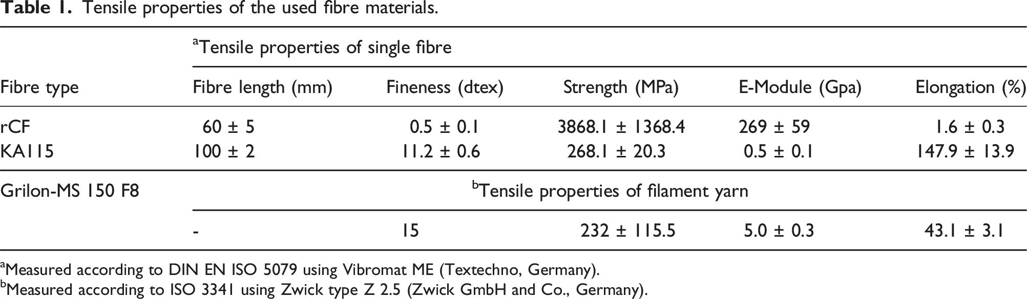
aMeasured according to DIN EN ISO 5079 using Vibromat ME (Textechno, Germany).
bMeasured according to ISO 3341 using Zwick type Z 2.5 (Zwick GmbH and Co., Germany).
Development of rCF yarns
Two different types of rCF yarns such as wrap and friction spun yarns were developed for the investigations in this work. A drawn sliver of rCF was used as the core of the yarns. The rCF in the core of the yarns serves as the basis for the reinforcement of the subsequent composite. To produce the drawn sliver, card slivers were first produced from rCF on a modified carding machine. The card slivers were then drawn on the draw frame using a modified levelling unit to produce a drawn sliver with a defined linear density and high uniformity. Details of the production of the card and drawn sliver are reported in Ref. 45.
A test rig developed at ITM was used for the production of wrap spun yarns. It is consisted of a drawing, twisting and winding unit. A wrap yarn was produced with the twist of the wrap filament yarn at 300 T/m. Two Grilon MS 150 F8 filament yarns (15 tex each) were used to wrap the core fibres. A friction spun yarn with a core-sheath structure was produced on a DREF-3000 friction spinning machine modified at ITM (Fehrer AG, Linz/Austria). The sheath of KA115 serves to stabilise the core rCF. The core to sheath ratio of the friction spun yarn was 92:08 wt%. The yarn was produced at a speed of 4000 rpm for the opening roller and 2000 rpm for the spinning drum. The fineness of all yarns was 900 tex.
Manufacturing of UD thermoset composites
In order to determine the mechanical properties of the composites made from the developed yarns, UD composite panels with dimensions of 300 mm × 260 mm×2 mm (length × width × thickness) were produced. For this purpose, the yarn was unidirectionally wound on a winding frame (IWT Industrielle Wickeltechnik GmbH, Germany). The unidirectionally wound yarn was impregnated using the resin transfer moulding (RTM) technique. Epoxy resin RIMR 135 (Hexion Speciality Chemicals, Germany) and hardener RIMH 137 (Hexion Speciality Chemicals, Germany) were used as the matrix in a mixing ratio of 100:35 by weight. Infiltration was carried out at 80°C.
In addition, to improve the bonding between rCF and resin in composites, the wrapped yarn was treated at 180°C for 5 minutes. The idea was to melt the copolyamide fibre of the sheath prior to impregnation with the matrix. This approach was found to be advantageous for improving the tensile properties of composites because of the temperature treatment prior to impregnation with resin as reported in Ref. 47.
Test specimens measuring 250 mm × 25 mm (L × B) and 40 mm × 15 mm (L × B) were then cut from the consolidated composite plates in the 0° direction for tensile testing (DIN EN ISO 527-5) and Charpy impact tests (DIN EN ISO 179-1), respectively. The tensile test specimens were prepared with tapered end tabs (50 mm × 25 mm) based on glass fibre reinforced composites, glued in place with Loctite 401 instant adhesive. These were used to protect the specimens from the jaws of the testing machine and to prevent clamping failures due to localised damage to the material.
Characterisations of yarns and composites
The actual rCF content of the rCF yarns and UD composites was determined using a muffle furnace (Nabertherm Controller B170) in accordance with DIN EN ISO 1172:1998. The yarn and UD composite test specimens were initially weighed, subsequently heated to 450°C for 1 hour to fully remove the matrix through combustion, and then reweighed. The rCF volume fraction of the yarn and composite specimen was calculated based on the weight loss, using the densities of rCF (1.8 g/cm3) and epoxy resin (1.14 g/cm3).
The tensile properties of the UD composite specimen were determined using a Zwick type Z 100 instrument (Zwick GmbH and Co., Germany) following DIN EN ISO 527-5. The tensile test was performed at a crosshead speed of 2 mm/min and a test length of 150 mm. The composite’s tensile strain was measured using an optical light sensor. To ensure accurate strain detection, reflective markers were placed at both ends of the specimen. During the test, the optical sensor continuously tracked the displacement of these markers, allowing precise strain calculation. The Young’s modulus was determined by analyzing the correlation between the measured tensile strength and strain within the elongation range of 0.05 to 0.15%. The testXpert® software from Zwick GmbH and Co. was used for this purpose. The impact tests were conducted using the Charpy-Impact tester CEAST 9050 (Instron GmbH, Germany). The impact strength of composites was determined by normalising the total absorbed energy by the cross-sectional area. Each configuration was measured at least five times to obtain the average value.
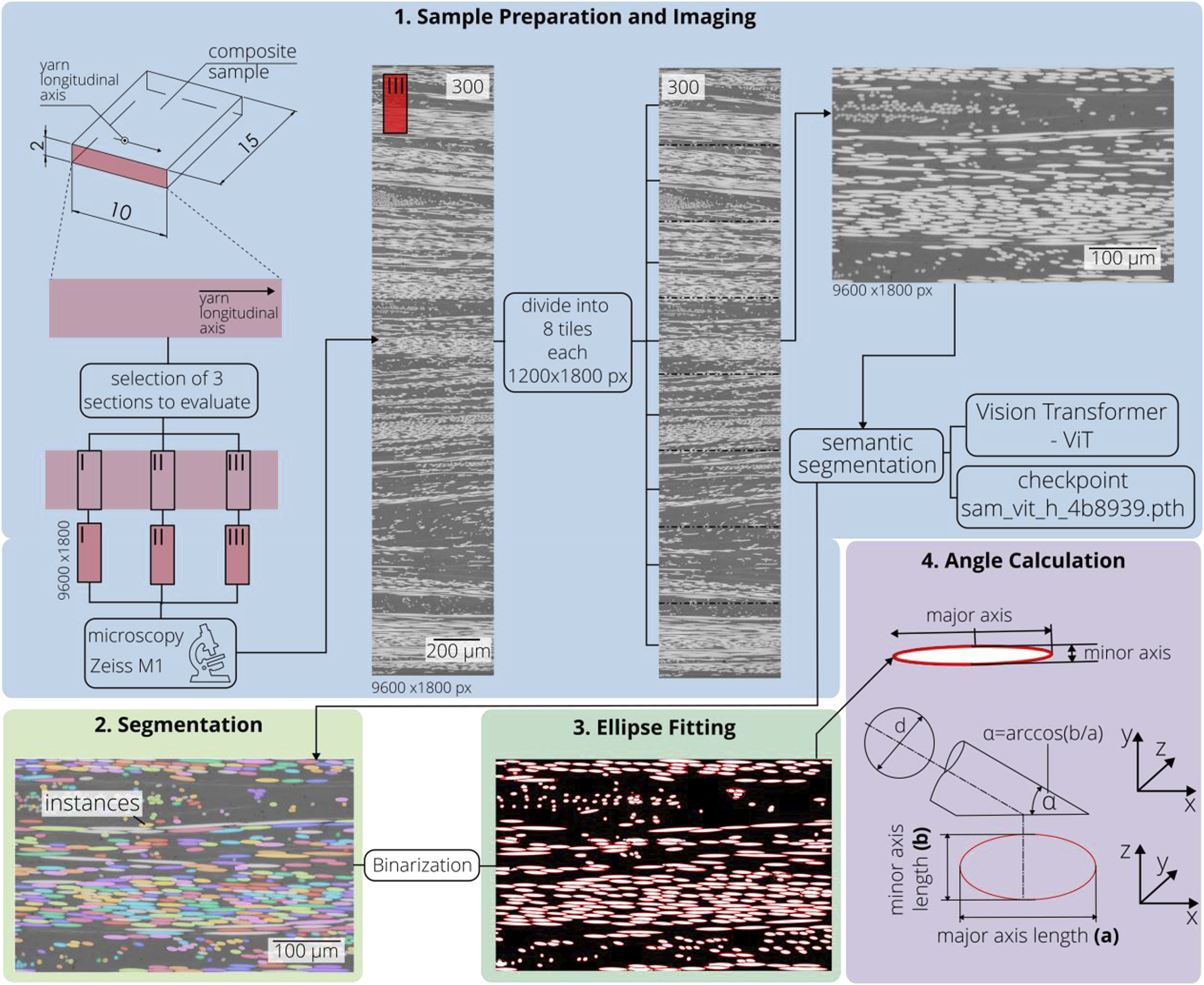
In addition, to investigate the influence of yarn structure on the orientation of rCF within the composite, the so-called method of ellipses
48
was employed for the evaluation of cross-sectional microscopic images. Due to the high compaction of fibres within the cross-section, conventional image segmentation techniques were deemed unsuitable, as overlapping fibres often result in incorrect segmentation, where multiple fibres are erroneously interpreted as a single entity. To address this limitation, a more precise segmentation method was implemented, tailored to accurately distinguish individual fibres. This approach provides a cost-effective alternative to the use of computationally and financially intensive computer tomography (CT) scans fibre orientation analysis. The method encompasses the following four steps (Figure 1): 1. Sample Preparation and Imaging: Composite samples with dimensions of 10 × 15 × 2 mm3 (L × W × H) were embedded in an epoxy resin matrix and cured at room temperature. After polishing and cleaning, cross-sectional images of the composites were captured using an optical microscope, specifically the Axio Imager M1m model from Carl Zeiss (Germany). Cross sections parallel to the longitudinal axis of the yarns were imaged. For each sample group, three sectional images were taken at different locations (middle and two outer regions). The dimensions of the images were 9600 px in height and 1800 px in width. Each sectional image was further divided into tiles of 1200 px in height and 1800 px in width. 2. Segmentation: To determine the orientation of each fibre, a high-quality segmentation method was employed. Conventional segmentation methods such as global thresholding, Otsu’s method, edge detection, watershed algorithm, and K-means clustering did not perform adequately. Therefore, the Segment Anything Model (SAM) was utilized for instance segmentation of the cross-sectional images. The encoder model used was the Vision Transformer (ViT) model with a backbone size of huge (h) - specifically the ViT-H SAM model without fine-tuning.
49
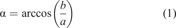
3. Ellipse Fitting: Ellipses were fitted to the segmented instances in the images. For each object segmented by SAM, an ellipse was calculated. 4. Angle Calculation: The lengths of the major (a) and minor (b) axes of each ellipse were measured. The angle (θ) at which a cylinder is cut by a plane, given the lengths of the major and minor axes of the resulting elliptical cross-section, was calculated using the formula: Different steps for the characterisation of fibre orientation in composite.
Results and discussion
A comparison of the structural differences between the friction and wrap spun yarn used in this study illustrated in Figure 2, shows that the friction spun yarn has a more compact structure and a smaller diameter than the wrap spun yarn, although the fineness of both yarns is the same at 900 tex. The friction spun yarn is a core-sheath structure where the core is rCF and the sheath is thermoplastic KA115 fibre. The compactness in friction spun yarns is achieved by wrapping the rCF core with KA115 sheath fibres, which increases the radial force on the core and compresses the yarn structure. The rCF content of the friction spun yarn depends on the core to sheath ratio of the yarn and the lower the sheath proportion, the higher the rCF content. On the other hand, a low sheath proportion is also essential for good penetration of the liquid epoxy resin during composite manufacturing. However, the strength of the yarn and the stable spinning process are greatly affected by reducing the sheath percentage below a certain limit. Therefore, for the production of the friction spun yarn taking into account all influencing factors suitable for thermoset composites, a minimum sheath content of thermoplastic KA115 of 8% is maintained in this work, which is essential to achieve a high rCF content and satisfactory yarn strength, as well as stable spinning and penetration of the liquid epoxy resin during composite production. The measured rCF content of the friction-spun yarn is 91.9 ± 0.7 wt%. Longitudinal images of wrap and friction spun yarn (both yarn fineness: 900 tex).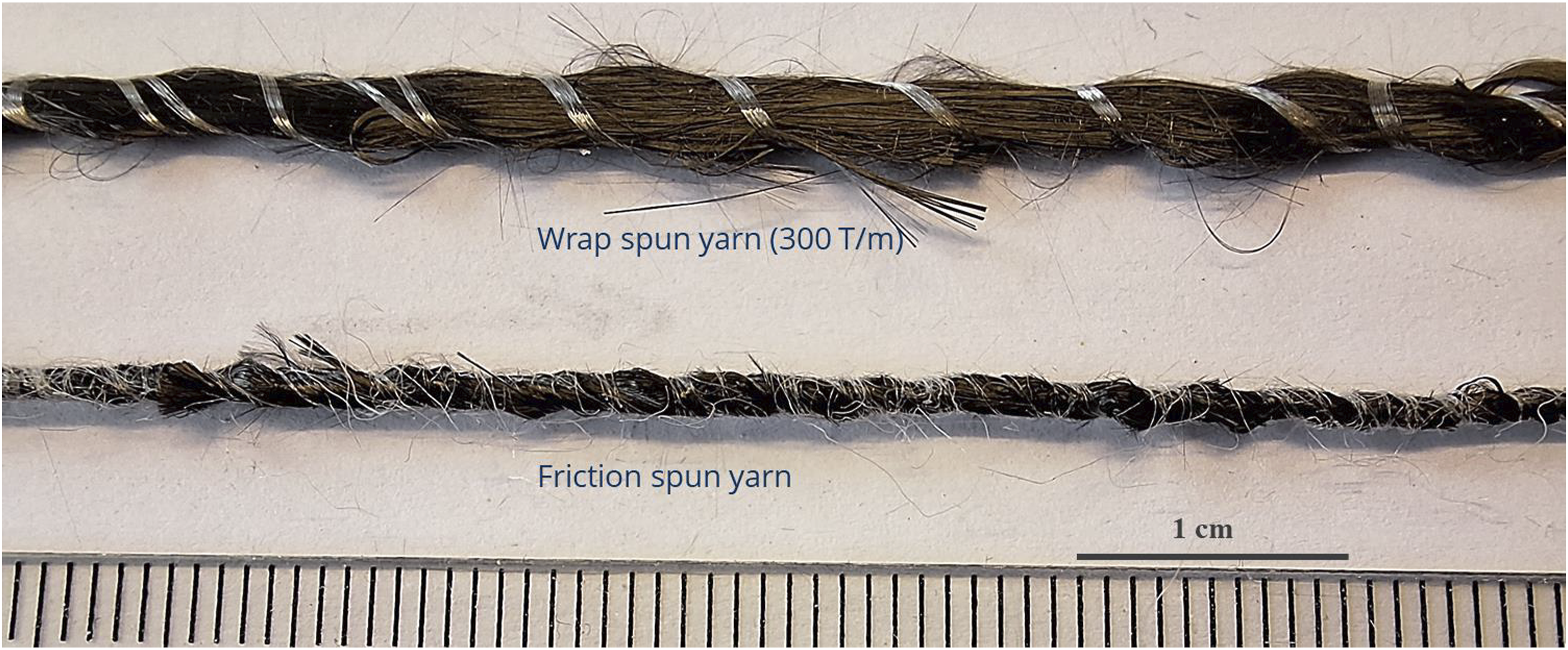
The wrap spun yarn, consisting of rCF in the core, is wrapped with two Grilon MS 150 F8 filament yarns. Unlike friction spun yarn, the compactness of wrap spun yarn depends on the twist of the wrap filament yarn. The higher the twist of the wrap filament yarn, the higher the yarn compactness and consequently the lower the yarn hairiness as reported in Ref. 46. The wrap yarn used in this study is produced with a twist of 300 T/m to ensure sufficient yarn strength and low hairiness. The measured rCF content of the wrap spun yarn is 93.3 ± 0.8 wt%.
In addition, a difference in yarn hairiness can be seen in the longitudinal view: the wrap spun yarn shows more protruding rCF fibres due to the lower coverage of the rCF core by the wrap filament yarn compared to the friction spun yarn. These characteristics, i. e. compactness and hairiness, play a major role in their further processing behaviour required for fabric manufacturing. In particular, the sheath fibres ensure a relatively dust-free weaving process for friction spun yarns. In addition, the smoothness or reduced hairiness of friction spun yarns facilitates shed formation during weaving.
In order to investigate the effect of sheath fibre (for friction spun yarn) und wrapping filament yarn (for wrap spun yarn) on the consolidation of composites, the composite production was carried out using two methods: with heat treatment (at 180°C for 5 minutes) and without heat treatment as mentioned before. Figure 3(a)–(h) present the composite specimens made from wrap-spun and friction-spun yarns, both with and without thermal treatment, before and after tensile testing. The stress-elongation behaviour of the composites during tensile testing, comparing thermally treated and untreated specimens for both yarn types, is illustrated in Figure 4. The investigations reveal that the stress-elongation curves of composites produced with thermal treatment are generally stiffer for both yarn types compared to those produced without heat treatment. It is noteworthy that the composites were fabricated by winding yarns unidirectionally onto a frame, which was removed prior to the infiltration process. The thermal treatment, involving the melting and cooling of the thermoplastic component in the yarns, enhances their rigidity. This process allows the yarns to retain their alignment and tension even after the removal of the wrapping frame, maintaining a straight and stretched configuration. In contrast, yarns without thermal treatment tend to relax, losing some of their structural tension. This increased rigidity and maintained alignment in heat treated yarns is likely a significant factor contributing to the higher stiffness observed in the corresponding composites. Effect of heat treatment on the consolidation of composites with different yarn structures. (a and b) Wrap spun yarn composite specimens without heat treatment: before (a) and after (b) tensile testing. (c and d) Wrap spun yarn composite specimens with heat treatment: before (c) and after (d) tensile testing. (e and f) Friction spun yarn composite specimens without heat treatment: before (e) and after (f) tensile testing. (g and h) Friction spun yarn composite specimens with heat treatment: before (g) and after (h) tensile testing. Effect of heat treatment on the tensile properties of composites based on wrap (a) and friction (b) spun yarns.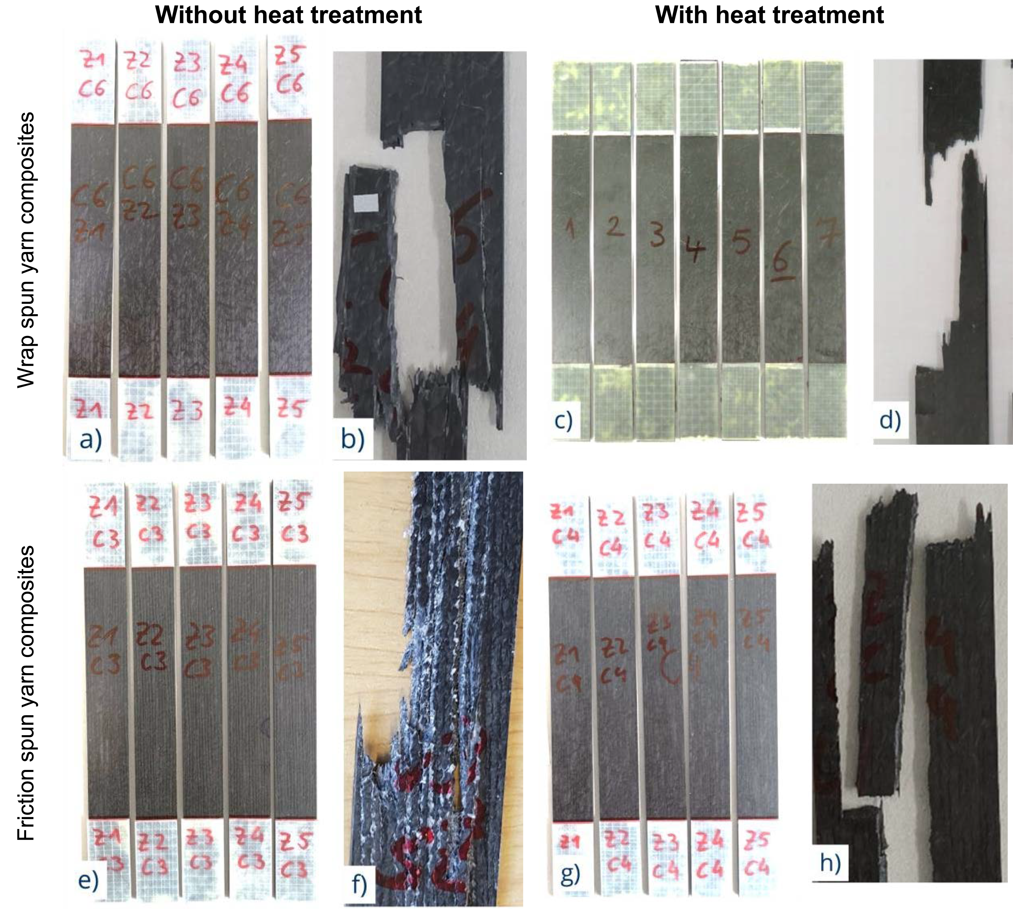
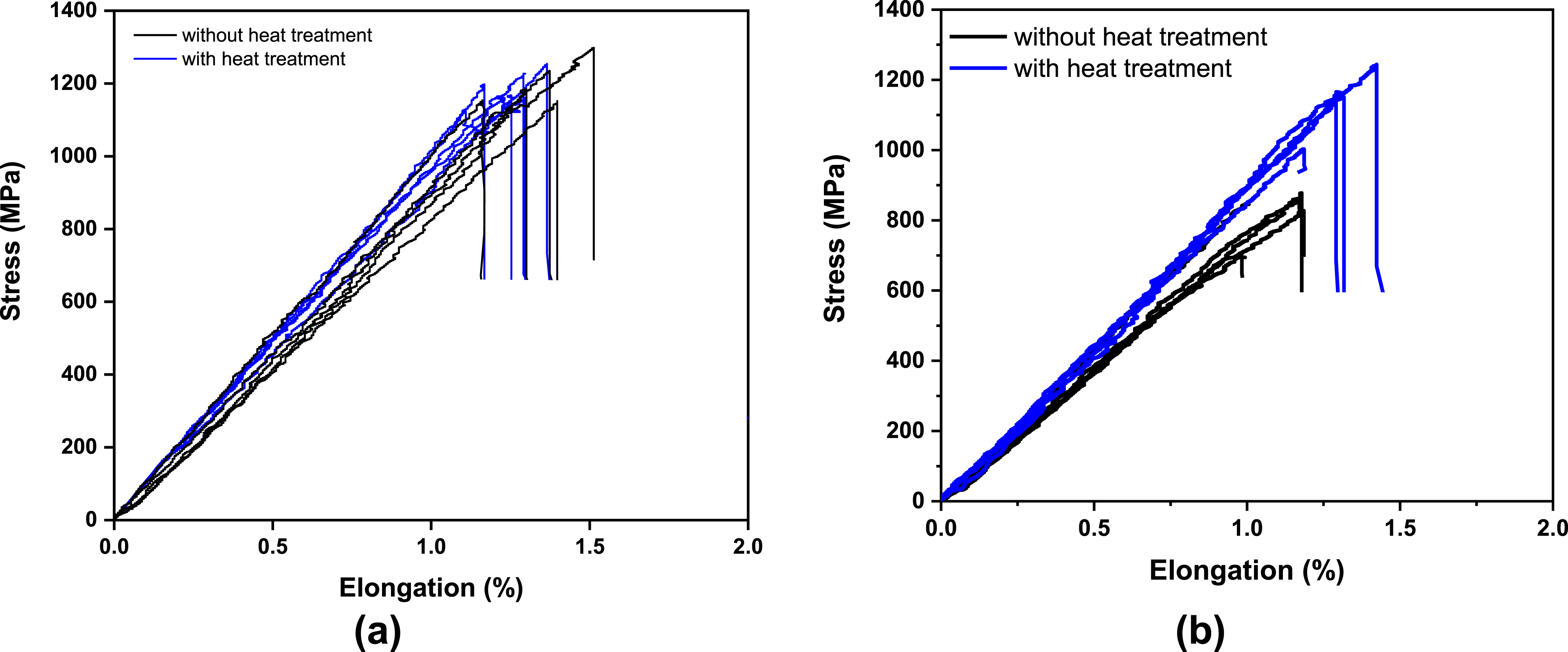
In the case of wrap spun yarns, the difference in average tensile strength between thermally treated and untreated yarns is not significant. From the fracture zones of the composites after tensile testing no distinct pattern can be observed Figure 3(b) and (d). This can be attributed to the good resin infiltration during composite manufacturing due to the open structure of the wrap yarn. The measured fibre volume content of the untreated and heat treated wrap spun yarn composite is also the same 39.5 ± 0.7 vol% and 39.5 ± 0.5 vol% respectively.
On the other hand, the visual appearance of the composite plate produced using the developed friction spun yarn with an 8% sheath shows that the consolidation is also good, i. e. no dry spots or irregularities (Figure 3(e)). However, the tensile strength of the composite material produced with heat treatment is significantly higher than that of the composite material produced without heat treatment. Due to the heat treatment, the tensile strength is increased by 36% compared to the one without heat treatment (Figure 4(b)). 47 Examination of the fracture zone after tensile testing of the composite specimen also shows a pronounced difference in the fracture pattern. In the case of the friction spun composite without heat treatment, the presence of KA115 fibre layer can be seen. This is attributed to the weak position and the main cause of crack initiation and leads to early composite failure, resulting in low tensile strength and a pronounced splitting pattern (Figure 3(f)). On the other hand, the fracture zones of the tensile specimen with heat treatment show no splitting pattern and no layer of KA115 fibre is visible in the fracture zone of the specimen after tensile testing (Figure 3(h)). It appears that the molten co-polyamide fibre promotes higher adhesion between the rCF and the molten co-polyamide fibre as well as between the molten co-polyamide fibre and the matrix compared to the composites without prior thermal treatment 50 leading to improved overall bonding in the composite. Moreover, the melted co-polyamide fibre’s continuous phase enhances the bond between the rCF and the matrix. As a result, the load transfer between the matrix and the reinforcing fibre is more efficient. Thus, the composites manufactured from thermally treated yarns exhibit higher load carrying capacity compared to those made from untreated yarns. The measured fibre volume content of the untreated and heat treated friction spun yarn composite is 39.6 ± 0.1 vol% and 41.7 ± 0.1 vol% respectively. It can be assumed that the dry KA115 fibre of the sheath (in the case of no heat treatment) absorbs more resin than the molten KA115 (in the case of heat treatment) during resin infiltration. The reason lies in the fact that the friction spun yarns before heat treatment are more voluminous due to the dry fibre on the sheath. After the sheath fibre has been melted by the heat treatment, the volume is reduced and the yarn becomes more compact. Due to the higher volume of the fibre structure, more resin is generally infiltrated into the RTM tool for non heat treated friction spun yarns than for heat treated friction spun yarn structures. As a result, the fibre volume content is slightly lower in the non heat treated friction spun yarn based composite.
To comprehensively analyze the properties of the composite, both the fibre orientation and cross-section of the composite specimen were examined. The results show that the cross-sectional areas of composites can be classified based on resin reach areas and fibre orientation (Figure 5). More resin reach areas can be seen in the wrap spun composites. This also explains the tendency for the wrap spun composite to have a lower fibre volume content than the friction spun composite. Longitudinal cross-section of composites (top), categorization map of fibre orientation (middle), and heatmap of fibre orientation angle (bottom) for composites produced from wrap spun yarn (left) and friction spun yarn (right).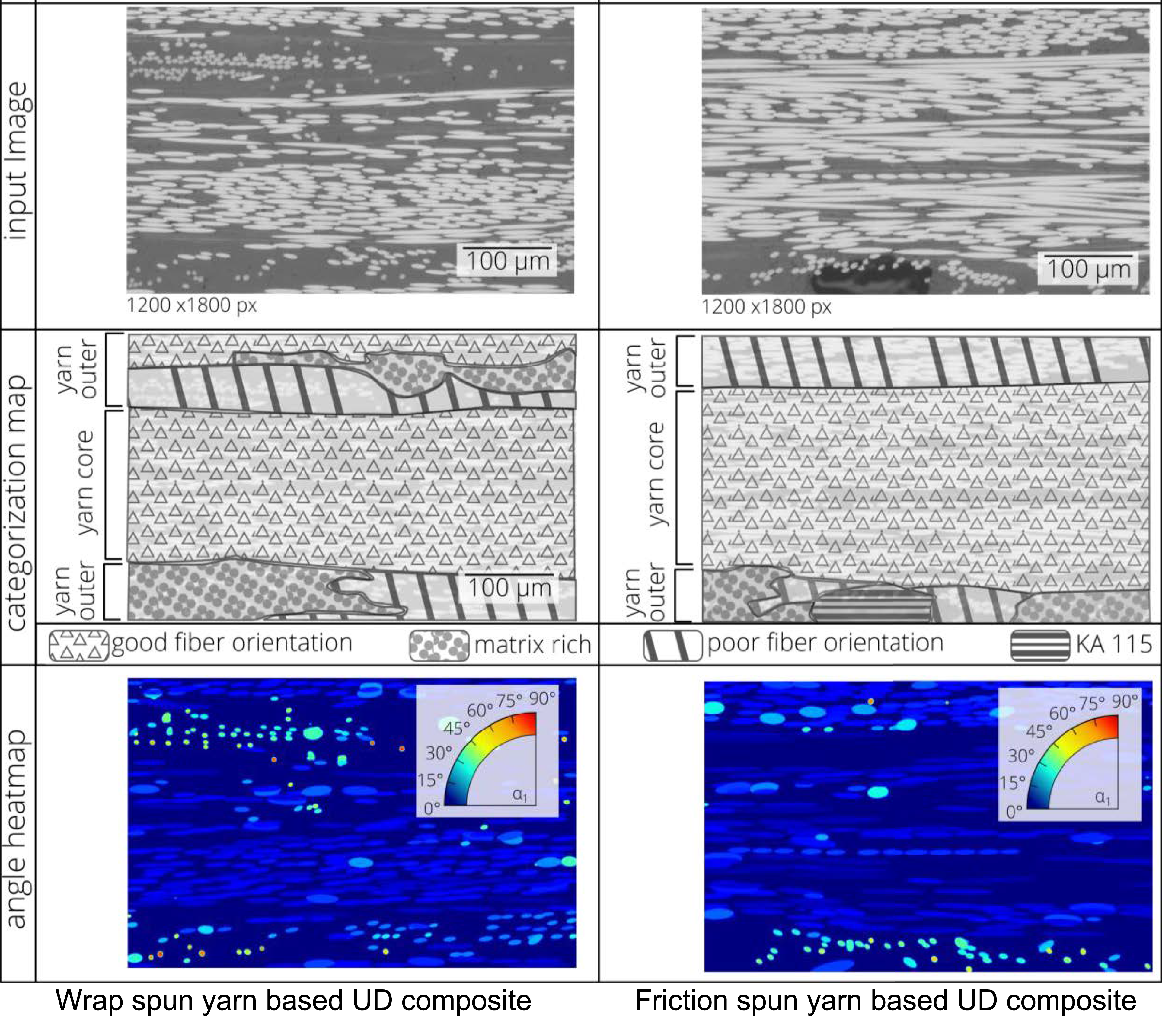
From the longitudinal direction of the composite cross section, the cross sections of rCF at higher fibre orientation appear as ellipses with higher eccentricity than those at lower fibre orientation. The lower the fibre orientation, the cross sections of rCF appear as round shapes. Regions of higher orientation are attributed to the yarn core, while areas of lower orientation are associated with the outer sections of the yarn in both composites (Figure 5). The outer layers of the composite contain a higher number of protruding fibres, generally leading to less optimal fibre orientation. The colour of the fibre angle heatmap shows that the wrap spun composite has more light blue dots than the friction spun composite, indicating lower fibre orientation. The core fibre in the friction spun yarn based composite appears more elliptical in shape and the fibres are more compactly distributed, resulting in larger areas of well oriented fibres compared to the wrap spun composites.
Figure 6 illustrates the measured fibre angle using the longitudinal cross-section of the composites. Each data point represents the angle of one segmented fibre. The fibre angle is around 16.5° and 16.6° for composites based on wrap and friction spun yarn demonstrating a similar fibre orientation in the longitudinal direction. Two-sample t test shows that the there is no difference between the two sample means. However, the distribution of the fibre angle is narrower for the friction spun yarn than for the wrap spun yarn. The difference is due to the fact that the friction spun yarn, being free of hairiness, has less deviation in fibre orientation compared to the wrap spun yarn. The areas with lower fibre orientation indeed have a significant impact on the mechanical properties of the resulting composites. Specifically, regions with less aligned fibres can lead to reduced tensile strength and stiffness, as the load transfer efficiency between fibres and the matrix is compromised. As the variation in fibre angle is greater in wrap spun composites than in friction spun composites as shown in Figure 6, the potential of wrap spun composites is not fully exploited. Increasing the twist of the wrap filament yarn can effectively reduce hairiness, leading to improved fibre alignment. Fibre angle of composites produced from wrap and friction spun yarn.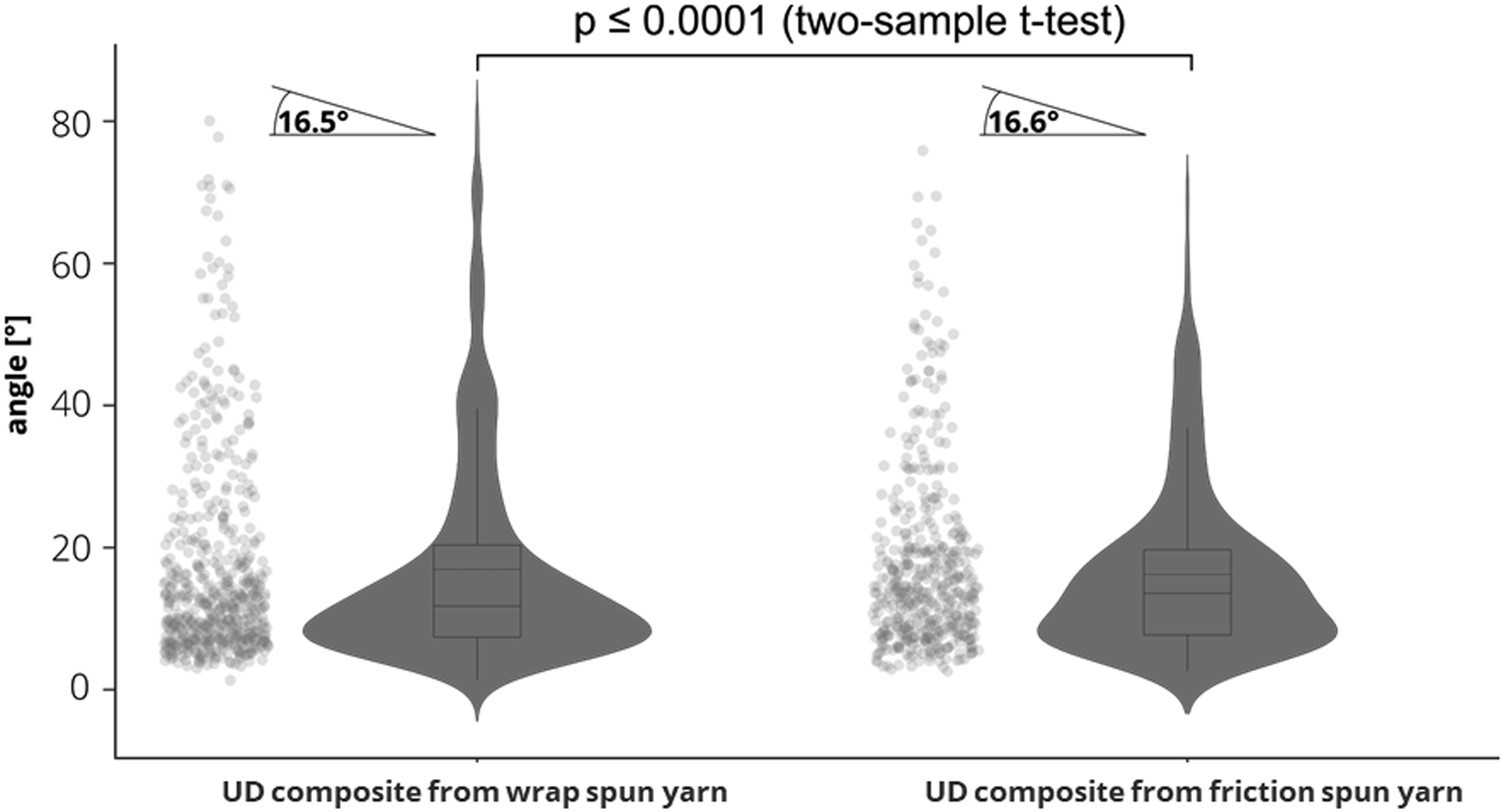
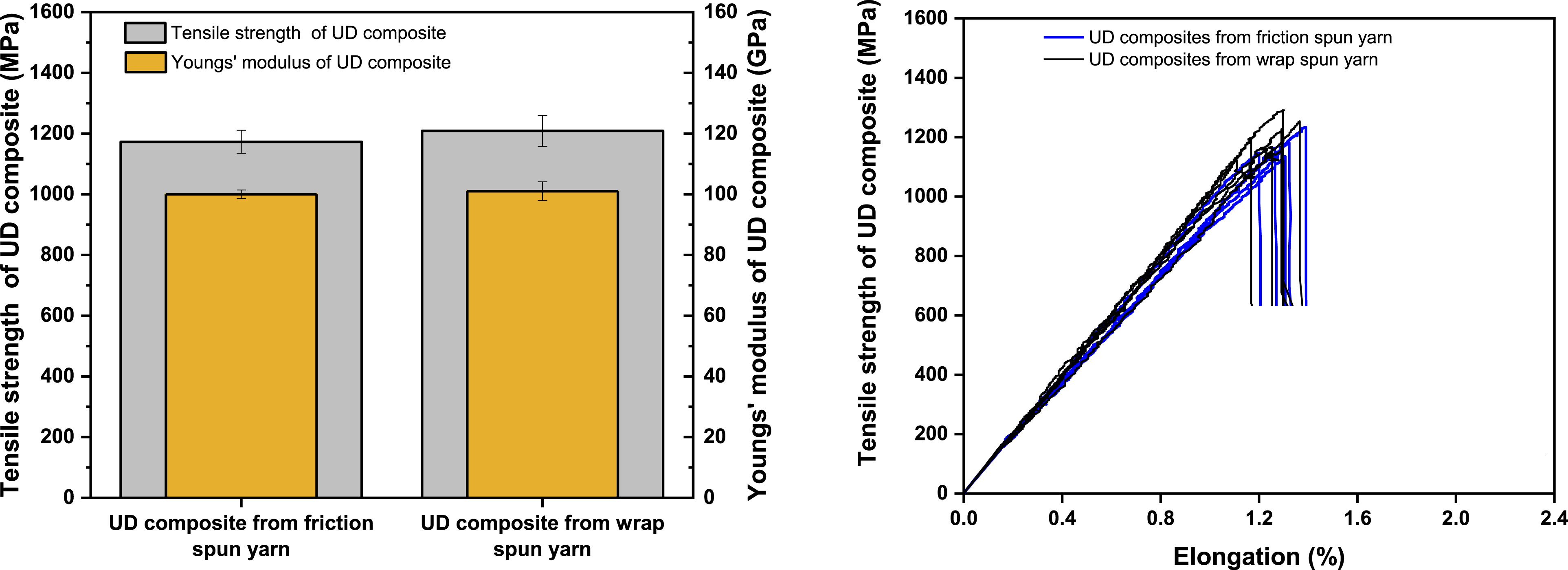
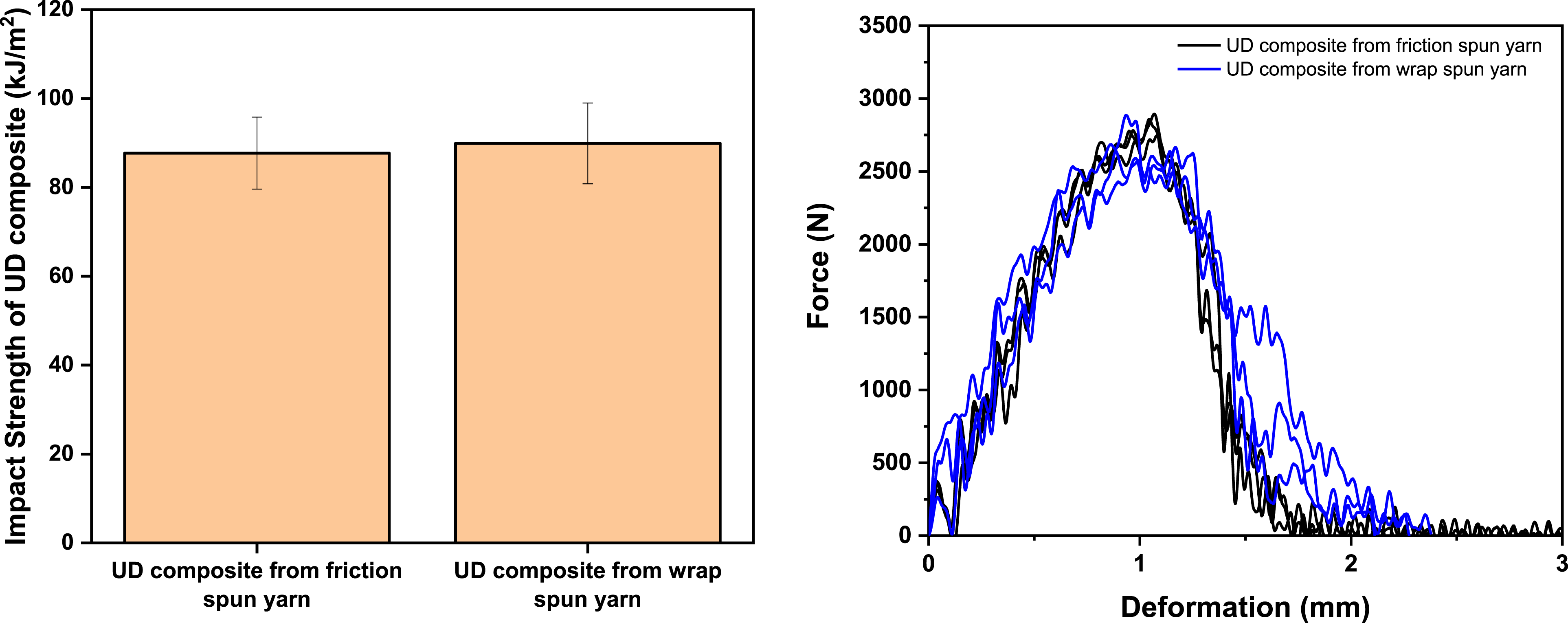
The effects of differences in yarn structures are evident in the composite specimen cross-sections (Figure 7). To facilitate comparison, both composites were produced by heat treating the yarns prior to infiltration. The wrap spun yarn, due to its more open structure, appears flatter within the composite, while the friction spun yarn maintains a rounder cross-section owing to its denser structure. Additionally, an accumulation of melted sheath fibres is visible at the interface between the rCF and matrix in the friction spun yarn composite. However, this accumulation does not affect the tensile strength and Young’s modulus for UD composites from friction spun yarn, shown in Figure 8. The tensile strength of composites based on wrap and friction spun yarn is 1209 ± 51 and 1173 ± 38 MPa, respectively. The Young’s modulus of composites based on wrap and friction spun yarn is 101 ± 3 and 100 ± 1 GPa, respectively. The same tendency can be found in the case of impact strength of composites (Figure 9). The charpy impact strength of composites based on wrap and friction spun yarn is 90 ± 9 and 88 ± 8 kJ/m2, respectively. Cross-sectional images of composites based on wrap (top) and friction (bottom) spun yarn [yarns were heat treated prior to infiltration]. Tensile strength and Youngs’ modulus (left) and strength elongation curves (right) of composites based on friction and wrap spun yarn. Charpy impact strength (left) and force-deformation curves of the Charpy impact test of composites based on friction and wrap spun yarn.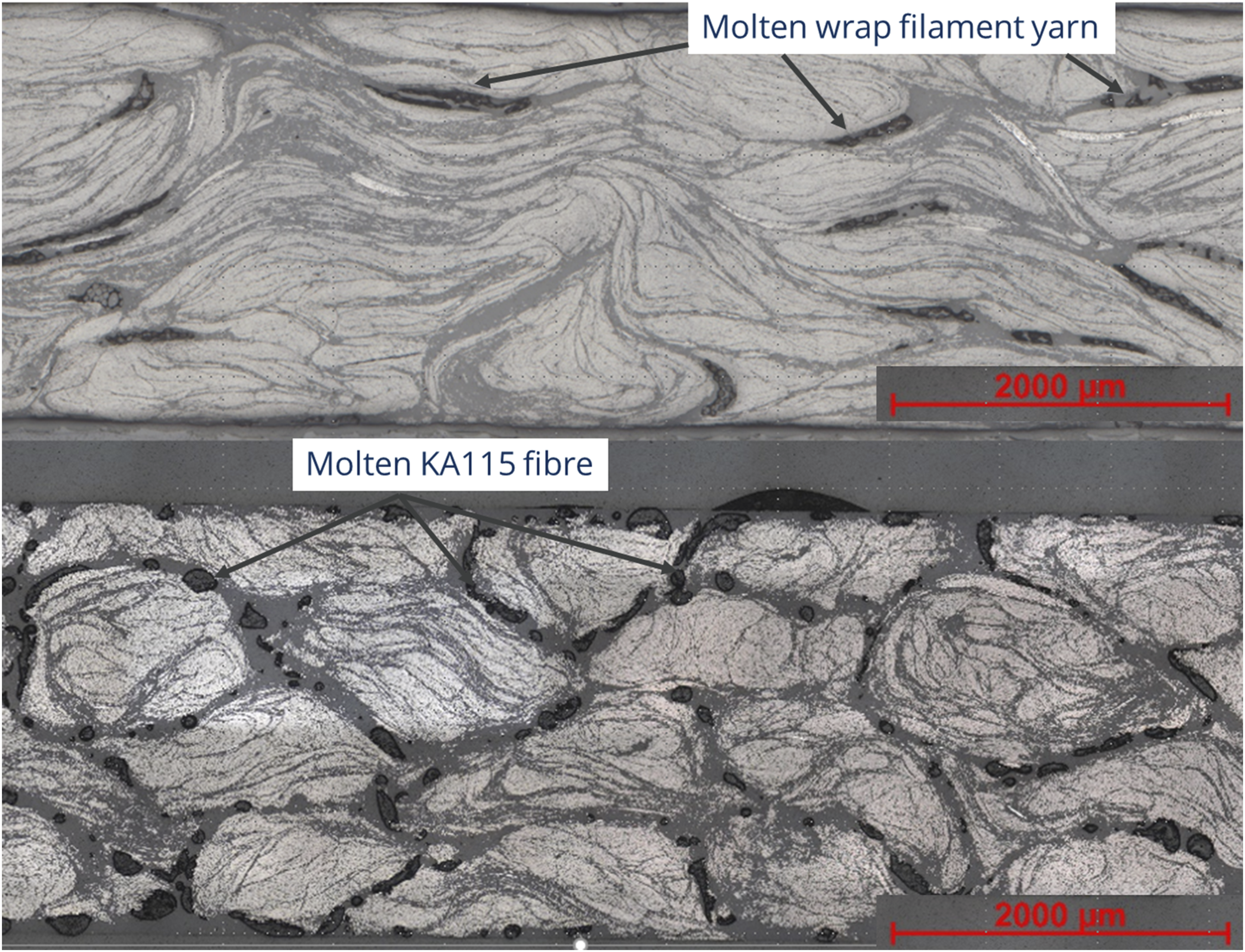
It is worth mentioning that the mechanical properties of the wrap spun reinforced composites were expected to be significantly better than those of the friction spun reinforced composites. This expectation was based on two key factors: (1) the open structure of wrap spun yarns, which facilitates better resin infiltration, and (2) the higher rCF content in the wrap spun yarn (93.3 ± 0.8 wt%) compared to friction spun yarns (91.9 ± 0.7 wt%). A higher rCF content and improved infiltration should theoretically enhance the composite’s mechanical performance. However, despite the higher rCF content in wrap spun yarns, this did not translate directly into a higher rCF content in the final composites. In fact, the fibre volume content in composites from heat treated wrap spun yarns was slightly lower (39.5 ± 0.5 vol%) than in composites from heat-treated friction spun yarns (41.7 ± 0.1 vol%) due to higher resin infiltration in the case of wrap spun yarns. This indicates that composites made from wrap spun yarns contained more resin rich areas, which could have influenced stress distribution and mechanical performance. In addition, the fibre orientation in wrap spun yarns tends to be lower than in friction yarns due to the higher hairiness, which can result in a more random fibre orientation within the composite. This reduced alignment could have offset the expected advantages of higher rCF content and better infiltration, leading to similar tensile and impact properties in composites between the two yarn architectures. The results indicate the complex relationship between yarn structure, fibre content, and composite performance.
Conclusion
The results in the paper show that the yarn structure of friction and wrap spun yarns has a significant effect on the compactness, hairiness and processability of these yarns. Despite these differences, the tensile and impact properties of thermoset composites made from both yarn types remain comparable, primarily due to the similar fibre orientation and fibre volume content within the composites. However, friction spun yarns require heat treatment to achieve good mechanical properties in composites. Composites based on wrap spun yarns, on the other hand, do not require any additional heat treatment prior to composite manufacturing.
These findings highlight the potential for further optimisation of the infiltration process for friction spun yarn in thermoset composites. Strategies such as incorporating sheath fibres fully soluble in the thermoset matrix or using epoxy resins chemically reactive with co-polyamide fibres could further enhance composite performance. Given the higher productivity and superior processability of friction-spun yarn compared to wrap-spun yarn, such optimizations could unlock greater efficiency and performance in composite manufacturing.
Footnotes
Acknowledgments
This article presents parts of the results achieved within the Project DFG- CH 174/55-1| GE 2525/5-1 funded by the Deutsche Forschungsgemeinschaft (DFG, German Research Foundation) – 442070201. The funding is gratefully acknowledged.
Declaration of conflicting interests
The author(s) declared no potential conflicts of interest with respect to the research, authorship, and/or publication of this article.
Funding
The author(s) disclosed receipt of the following financial support for the research, authorship, and/or publication of this article: Deutsche Forschungsgemeinschaft (DFG, German Research Foundation) – 442070201.
Data availability statement
Data sharing not applicable to this article as no datasets were generated or analyzed during the current study.