
Abstract
Hybrdization of CFRP with steel sheets enhances bolt-bearing performance. At room temperature, bearing strength is reported to increase while minimum edge and width distances decrease. To assess if this advantage persists under low temperature conditions, bolt-bearing tests following AITM 1-0009 are conducted at 23°C and −55°C. Various monolithic and hybrid configurations with different metal content and joint geometries are examined. Furthermore, ultrasound scanning and optical microscopy of the fracture plane is conducted. Hybridizing composites notably improves bearing capacity. However, the reinforcement effect is less pronounced at low temperatures compared to room temperature. The reduction in minimum edge and width distances with metal hybridization largely depends on the composite ply stacking, challenging general literature recommendations. Regarding damage mechanisms in the joints, fractography indicates that introduction of steel sheets relieves composite plies, isolates damage, and enhances load-bearing capacity through additional bending stiffness and significant plastic deformation of the metal.
Introduction
CFRP is widely used in lightweight design due to its high stiffness and strength at low density. However, CFRP also has drawbacks, such as low bearing strength, limited impact resistance, and a risk of delamination. In contrast, metals exhibit high bearing strength and good impact properties, but they also have high density and poor fatigue resistance. Combining composites and metals provides a solution to overcome these challenges. Notable examples include GLARE, a fiber metal laminate (FML) composed of aluminum and GFRP, offering superior fatigue properties at a reduced weight compared to pure aluminum.1–3 Another promising combination involves CFRP and titanium, showcasing compatibility in material stiffness and coefficient of thermal expansion (CTE), resulting in elevated bearing strength4,5 and temperature resistance.6,7 Combining CFRP and steel surpasses CFRP-titanium FMLs in stiffness and strength with significantly lower metal content. This material combination exhibits superior bearing capacity8,9,5 and high impact resistance. 10 Introducing steel/titanium hybridization to practical applications can have great advantages.
In general, enhancing the load bearing capacity of composite bolted joints involves local laminate build-up in the joining area. However, this method introduces additional stresses due to eccentricities, complex adjacent structures, and a substantial weight increase from larger grip lengths, fastener diameters, and heavier metallic fittings.5,11,12 Local metal hybridization in the joining area can be employed in order to increase bearing strength and coupling stiffness, simultaneously reducing sensitivity to laminate configuration. This approach not only prevents the need for laminate build-up but also offers the potential to reduce the number of bolts for a more efficient joint design. 12 Mechanical advantages and manufacturability of this technique have been validated at the coupon level13–15 and demonstrated on a component level using a spacecraft payload adapter. 5
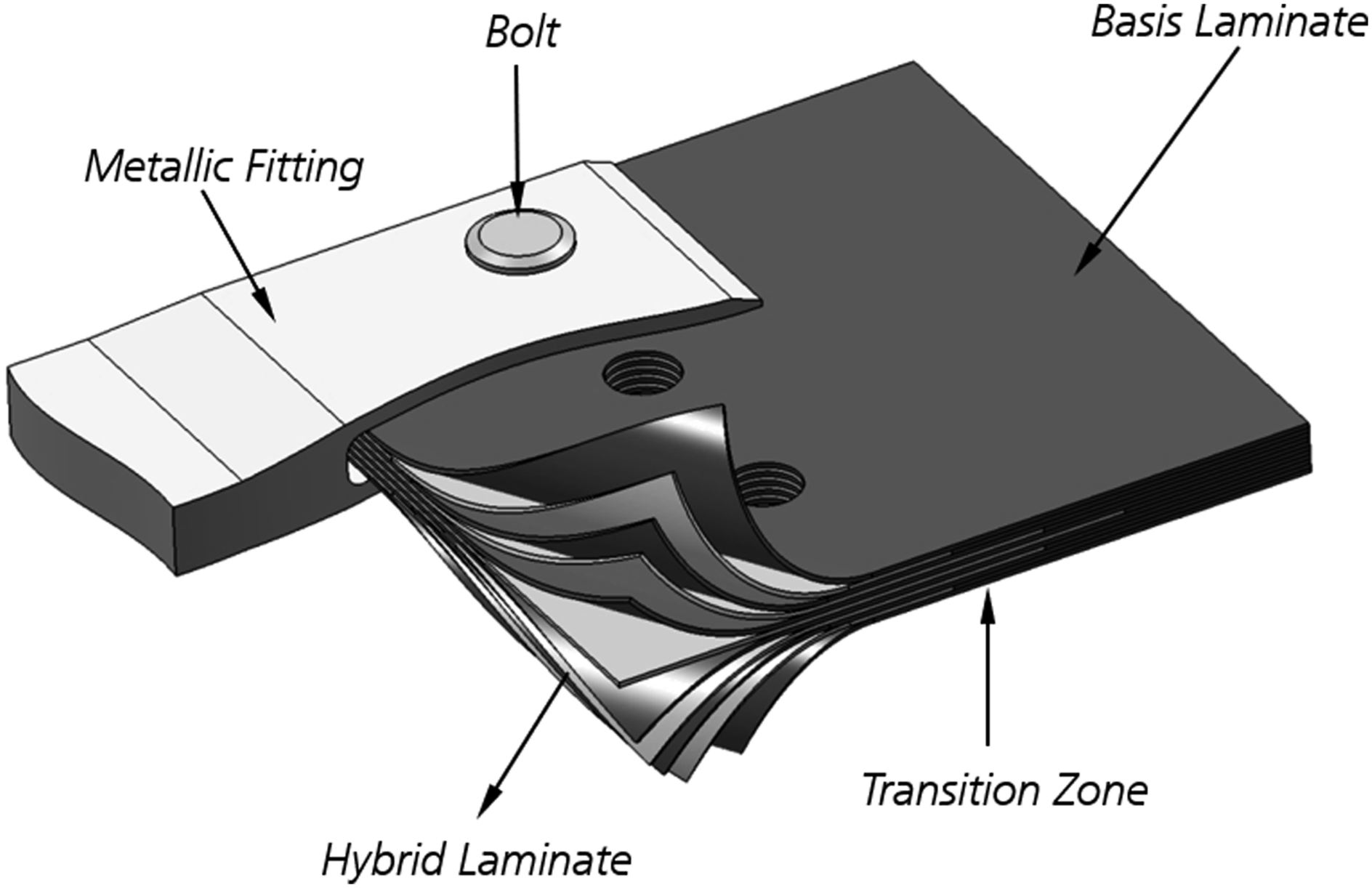
Figure 1 shows the concept of local metal hybridization in detail. By ply-substitution in the transition zone, metal sheets are embedded into the laminate, thus dividing the laminate into three zones: The fully hybridized joining zone increases the bearing capacity of the laminate and allows for a high local coupling efficiency. Ply loads from the joining zone are redistributed along the transition zone into the monolithic base laminate, which is in turn designed for the global loading case. The ply-substitution technique is most effective when replacing composite layers that contribute least to the material strength in loading direction, e.g. preferably 90° followed by ± 45° layers. Remaining layers pass continuously through the transition zone into the fully hybridized zone, thus ensuring laminate adhesive integrity and contributing to the laminate strength. Given that this technology is developed for highly loaded structures, the FML consituents usually consist of CFRP laminates reinforced with steel or titanium sheets, resulting in CFRP-St and CFRP-Ti FMLs, respectively. Concept of local metal hybridization in composites.
11
First studies were originated in the U.S. where
Mechanical benefits of local metal hybridization have been demostrated with respect to static and fatigue behavior as well as resistance to various environmental effects. Furthermore, manufacturing of highly complex structures has repeatedly been proven to be feasible. The vast majority of research on CFRP-St and CFRP-Ti FMLs was conducted at room temperature, while effects of high temperature were considered mainly during development of the original CFRP-Ti FMLs, namely HTCL and TiGr. Introduction of CFRP-St and CFRP-Ti laminates into air- and spacecraft structures, however, requires investigation of temperature effects within the entire range of operating temperatures. Yet, there is no substantial research on low temperature effects on steel and titanium reinforced composite bolted joints. Given the findings on CARALL/CARE, where large thermal residual stresses due to the difference in CTE renders application of that type of FML very unlikely, 31 it is remarkable that the performance of CFRP-St and CFRP-Ti hybridized composite bolted joints has not been addressed yet.
In monolithic CFRP laminates, a temperature decrease greatly affects the material intra- and interlaminar behavior. In general, bearing stiffness and strength increase with decreasing temperature,32–35 however, the presence of large thermal residual stresses can reduce the bearing capacity. 34 The failure characteristic is also influenced, indicating that an increase in delamination effects at low temperatures renders investigation of interlaminar properties more relevant. In Koord et al. 36 a first analysis of low temperature effects on delamination in CFRP-St FMLs is presented. However, the field of low temperature bearing behavior and interlaminar properties of CFRP-St and CFRP-Ti FMLs is yet to be explored more broadly. Due to the combination of large differences in CTE as well as material stiffness, inter- and intralaminar thermal residual stresses are expected to have significant influence on the material behavior. As a result, the question arises whether the increase in bearing strength by metal hybridization of monolithic CFRP laminates observed at room temperature also extends to low temperature conditions. Thus, in the present study steel hybridized CFRP bolted joints are analyzed. CFRP-St FMLs are chosen due to the large amount of thermal residual stresses resulting from the difference in CTE between CFRP and steel in combination with large stiffness.
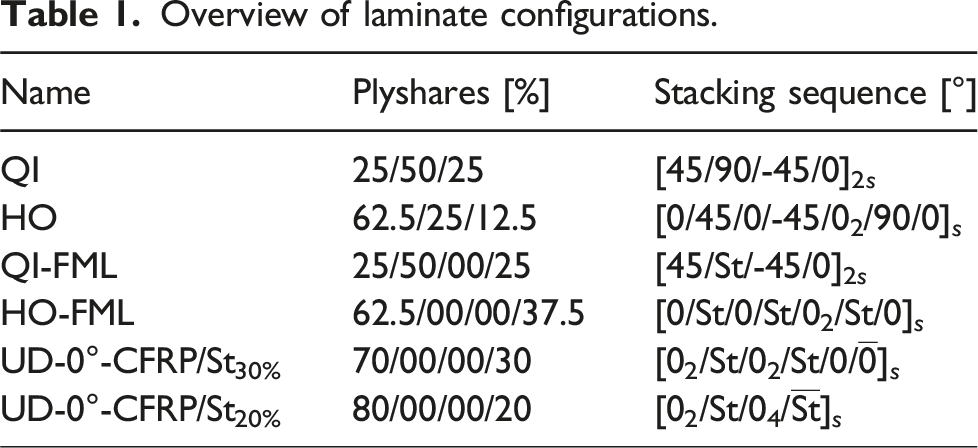
Overview of laminate configurations.
Experimental work
Specimen manufacturing
In total, 104 bolt bearing specimens are fabricated and tested using UD CFRP material (HexPly M21/35%/268gsm/T700GC) with a cured ply thickness of 0.26 mm and cold worked high strength steel sheets (St 1.4310) with a foil thickness of 0.26 mm. Manufacturing of the monolithic and hybrid specimens is identical except for an additional pre-treatment process for the metal layers of the hybrid specimens. The pre-treatment process for proper bonding between CFRP and metal layers developed at DLR
37
combines mechanical and chemical treatment by vacuum grit-blasting and subsequent sol-gel application. Four monolithic and six hybrid plates are manufactured by hand layup, vacuum sealed, and cured in an autoclave following the manufacturer’s recommended curing cycle. After the autoclave process, the specimens are cut to size by waterjet and measured using a micrometer. The specimen shape in Figure 2 is in accordance with AITM 1-0009 with a nominal hole diameter of 6.35 mm, a specimen width of 45 mm, and an edge distance of 25 mm. Only the specimens that are used to determine critical e/d and w/d ratios exhibit varying edge-distance and width, respectively. The holes are drilled using a solid carbid drill at 1200 rpm while clamping the specimen in between aluminum plates to prevent delamination. Due to wear, the drill heads are replaced after 3 and 5 drilled holes in case of hybrid and monolithic specimens, respectively. Ultrasound scanning and microscopy analysis is used to monitor the quality of the hole edges. After manufacturing, the specimens are stored at 23 ± 3°C and 50 ± 10% relative humidity until testing. In Figure 10 specimens with varying w/d rations are presented, while Figure 12 shows the microsections of the stackings for QI, HO, QI-FML and HO-FML. Bolt-bearing specimen geometry.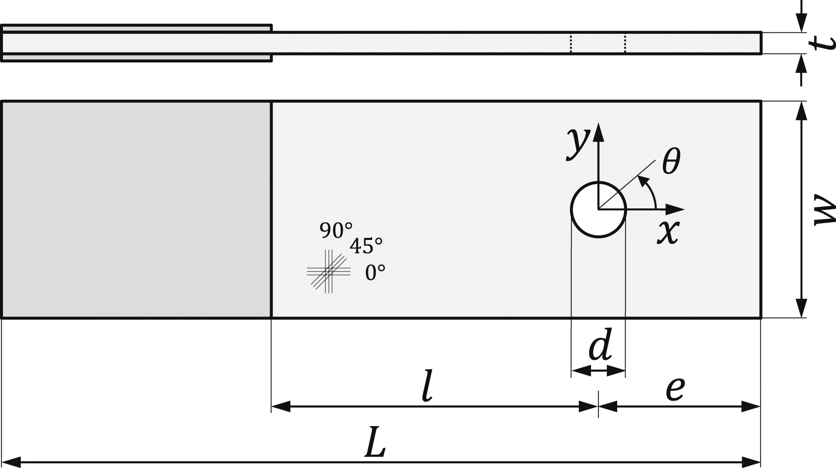
Test setup and procedure
The bearing behavior is experimentally characterized following AITM 1-0009 at two temperature levels: 23°C (RT) and −55°C (LT). The test setup, illustrated in Figure 3, is housed within a thermal chamber integrated into a Zwick servo-mechanic testing machine (Zwick 1484), featuring a 250 kN load cell. Hole elongation is determined using an extensometer, while the chamber temperature is continuously monitored by two resistance temperature sensors (Pt100). Bolt-bearing test setup conforming to AITM 1-0009 inside a temperature chamber with a test specimen in between two load plates and an extensometer as well as two temperature sensors attached to the setup.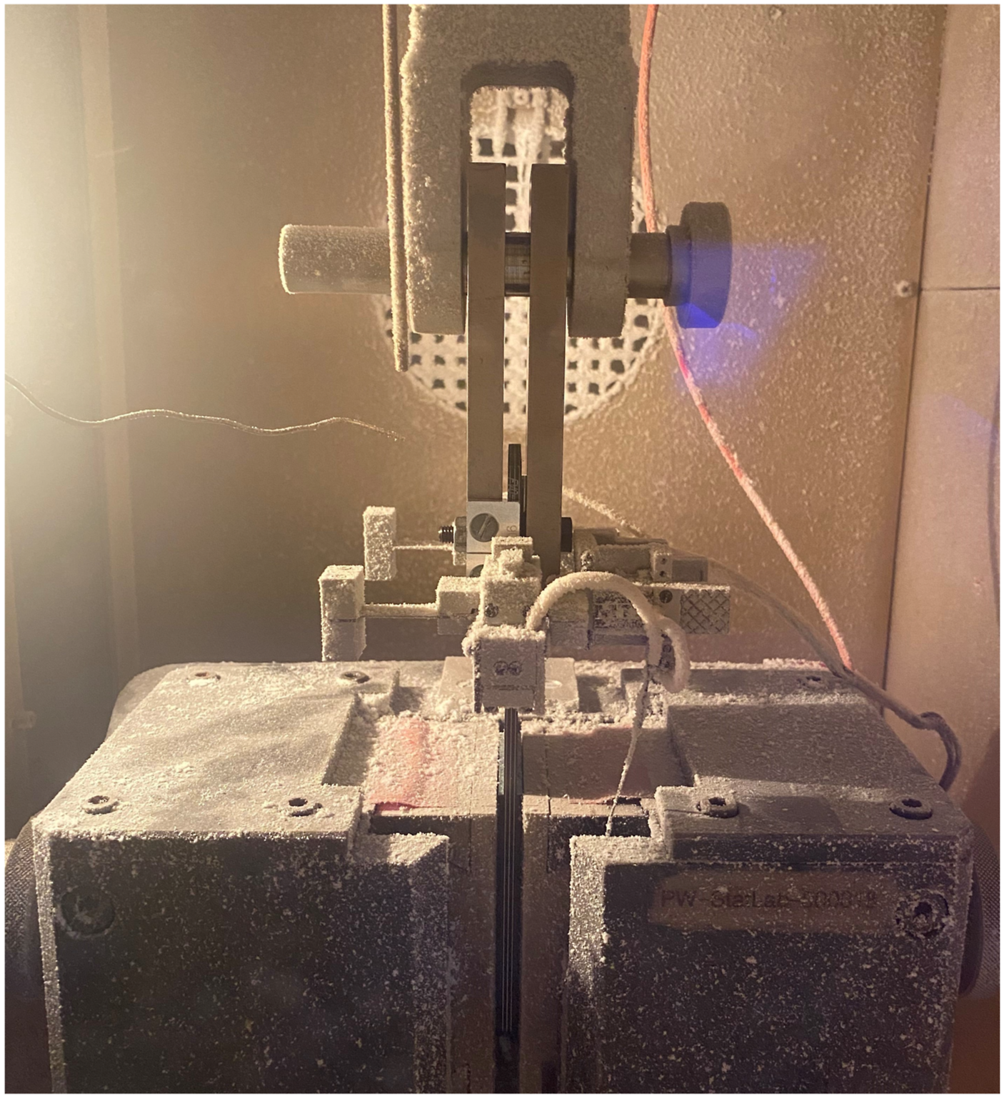
The test specimen is positioned between two loading plates in a double-lap configuration, mechanically fastened with a torque wrench at a bolt torque of 1.3 Nm using a high-strength bolt. The entire setup is then placed into the thermal chamber of the test rig, and the extensometer is mounted. Due to the setup’s substantial thermal mass, the test begins after a cooling time of 45 min. After completion of the bolt-bearing test, the setup is disassembled, and the load plates are immersed in a water basin for 30 min before being connected to the subsequent test specimen. This procedure ensures the repeatability of experiments, with thermal effects consistently occurring, such as changes in clamping torque due to setup contraction during cooling. No waiting periods are required for room temperature testing.
Bearing stress, defined as the bearing load over the projected bearing surface (P/dt), is assessed at five offset strengths with permanent hole deformations of 0.5, 2, 4, 6, and 10 %. Additionally, the bearing yield strength (BYS) at 0.5 % hole deformation and the bearing ultimate strength (BUS) at the maximum load sustained by the specimen during the test are distinguished.
Results and discussion
The effect of steel hybridization of CFRP bolted-joints at low temperature is studied in multiple steps. Firstly, the bolt-bearing behavior in terms of load-displacement curves of different monolithic and hybrid laminates is analyzed. Then, the effect of hybridization is discussed in more detail focusing on bearing strength, metal volume fraction (MVF) as well as joint geometry. In order to better understand the underlying mechanisms that are responsible for the hybridization effect, the damage behavior through analysis of ultrasound scans and microscopy of the bearing plane is studied in detail.
Bolt-bearing behavior
In Figure 4, the load-displacement behavior of the monolithic QI and HO laminates as well as their hybrid counterparts QI-FML and HO-FML are plotted. Each test series is comprised of n = 4 samples. The results are discussed with respect to initial joint stiffness, bearing strength and apparent ductility. Bolt bearing behavior of monolithic (HO, QI) and hybrid (HO-, QI-FML) laminates at RT and LT including offset lines indicating permanent hole elongations at approximately 0.5, 2, 4, 6 and 10 %.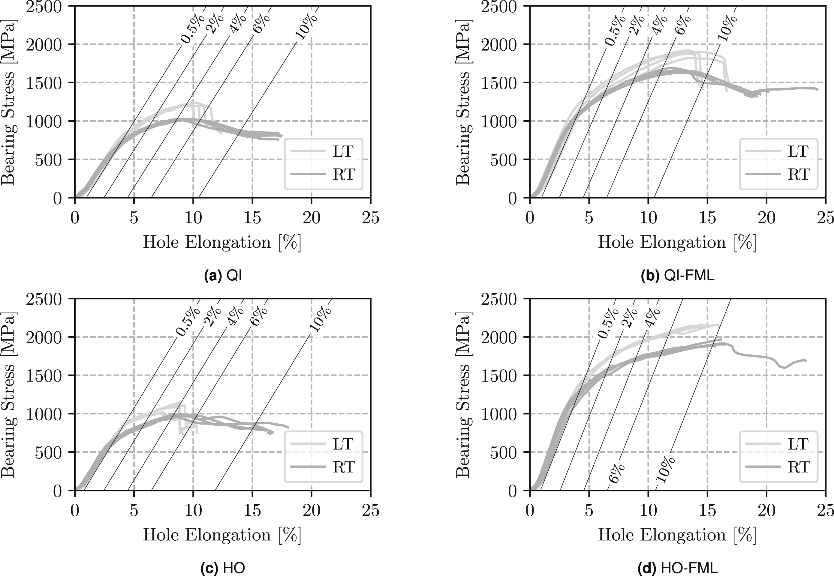
Decreasing temperature notably affects the load-bearing behavior of both monolithic and hybrid laminates. Therein, the bearing stresses sustained by the joints shift towards higher values at LT. In case of the monolithic laminates, the temperature decrease is accompanied by material embrittlement. While at RT, ultimate failure occurs at high bearing stress levels well beyond 10 % permanent hole elongation for both QI and HO laminates in Figure 4(a) and Figure 4(c), the behavior at LT reveals a sudden load drop between 4 % and 6 % permanent hole elongation. Depending on the metal content, hybridization with ductile metal can partially (QI-FML) or fully (HO-FML) compensate for the embrittlement caused by the temperature decrease in Figure 4(b) and Figure 4(d), respectively. Consequently, in contrast to monolithic laminates, FMLs exhibit quasi-ductile behavior even at low temperatures, demonstrating their favorable characteristics in terms of damage tolerance.
The strength increase for decreasing temperature in monolithic and hybrid composite bolted joints is discussed in more detail on the basis of BYS and BUS in Figure 5. Both mean value as well as standard deviation of BYS and BUS is plotted for the QI and HO as well as QI-FML and HO-FML. Plus, the relative increase in strength due to hybridization is indicated for each laminate with respect to both BYS and BUS. Strength-increase by hybridization of QI and HO laminates at LT and RT. (a) Strength-increase at LT. (b) Strength-increase at RT.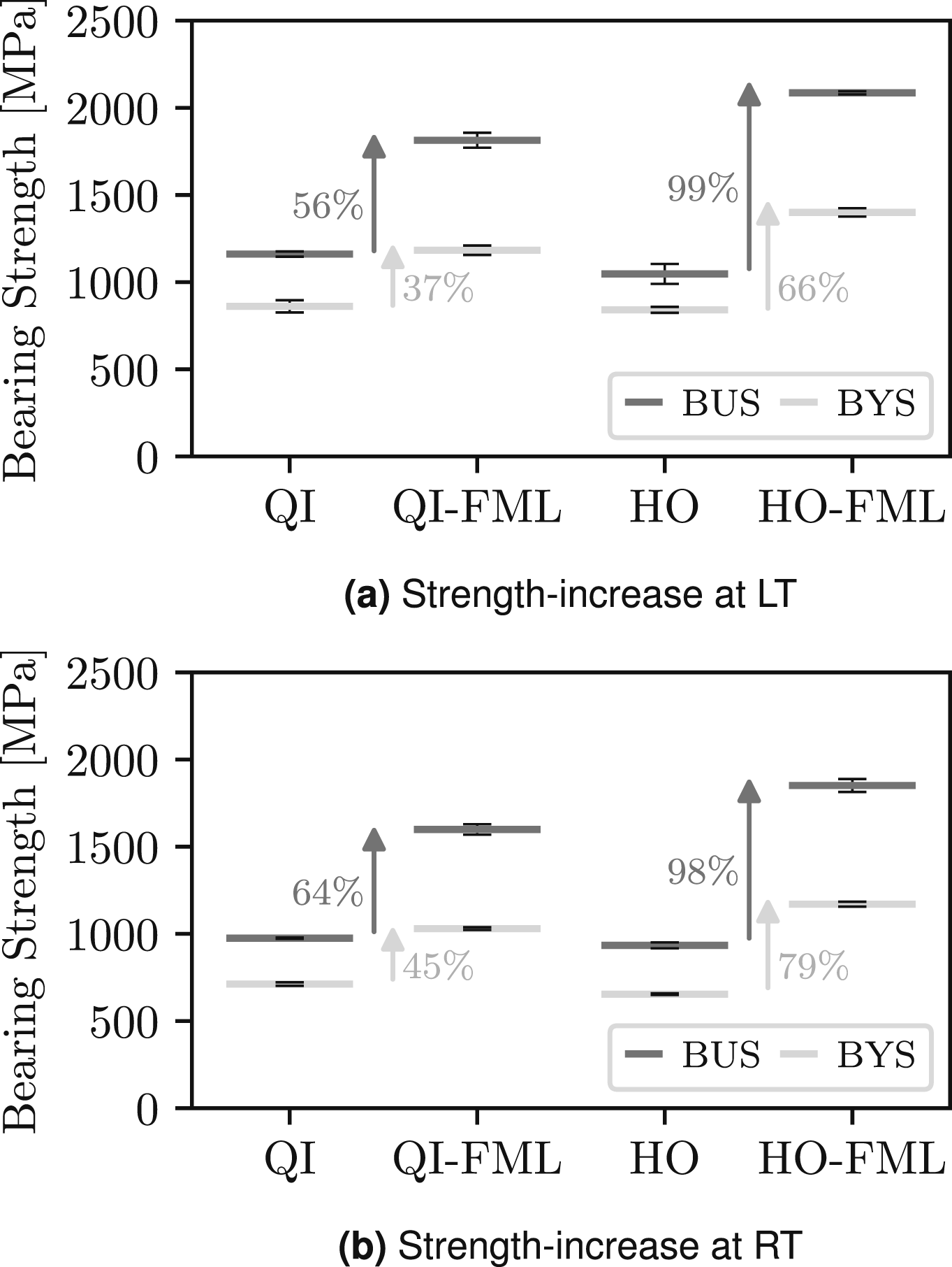
For both LT and RT as well as both BYS and BUS, the strength increase through hybridization is more pronounced for the HO laminate compared to the QI laminate. In Figure 5b for example, hybridizing the QI laminate results in a 45 % increase in BYS at RT, while hybridization of the HO laminate leads to a 79 % strength increase in BYS at RT. This difference in strength increase can be mainly attributed to the difference in MVF. While the QI-FML contains 25 % steel, the HO-FML has a MVF of 37.5 %.
Comparing BYS and BUS in Figure 5, hybridization is more effective with respect to BUS. Therein, the increase in BYS at RT in the QI and HO laminates through hybridization amounts to 45 % and 79 %, respectively. However, regarding BUS the strength increase through hybridization for the QI and HO lamiantes are 64 % and 99 %. The behavior at LT is similar. The present observation agrees with literature results, 11 where comprehensive experimental investigation of CFRP-St and CFRP-Ti FML bolted joints at RT is conducted. Therein, it is reported that the strength increase at BYS and BUS is based on different mechanisms. At BYS, the relief of composite plies by the metal layers, isolating damage within composite plies and suppressing damage growth through the metal sheets leads to increased load bearing capacity. However, at BUS, the dominating mechanism consists of an increase in out-of-plane stability due to the bending stiffness and extensive plastic deformation of the metal sheets, thereby resulting in an increase in strength. The section ”Damage analysis” provides a more detailed discussion on the strenghtening mechanisms through hybridization.
Effect of hybridization
Figure 6 shows the effect of hybridization at the example of representative load-displacement curves for monolithic QI and HO laminates as well as their hybridizations at LT and RT. It can be seen that there is a significant effect on both initial stiffness and load bearing capacity through steel hybridization. Effect of hybridization on monolithic QI and HO laminates at LT and RT. 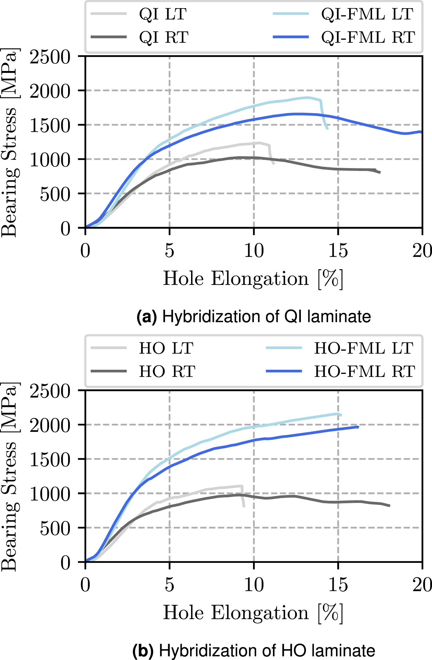
It is briefly mentioned in the preceding section that hybridization of CFRP bolted-joints improves the stiffness and load-bearing capacity as well as the apparent ductility of the joint, especially at LT. Therein, the sudden load drop of the QI laminate in Figure 6a is retarded toward higher deformation through hybridization, while hybridization of the HO laminate in Figure 6b eliminates the load drop at LT altogehter.
In Figure 7, the load-displacement curves for gradually increasing MVF are illustrated. In addition to the monolithic QI and HO laminates and the hybrid QI-FML and HO-FML, two additional UD-CFRP-steel FMLs are presented, thus encompassing MVFs ranging from 20 % to 37.5 %. Load-displacement curve for varying MVF (QI: 0 %, HO: 0 %, QI-FML: 25 %, HO-FML: 37.5 %) at LT.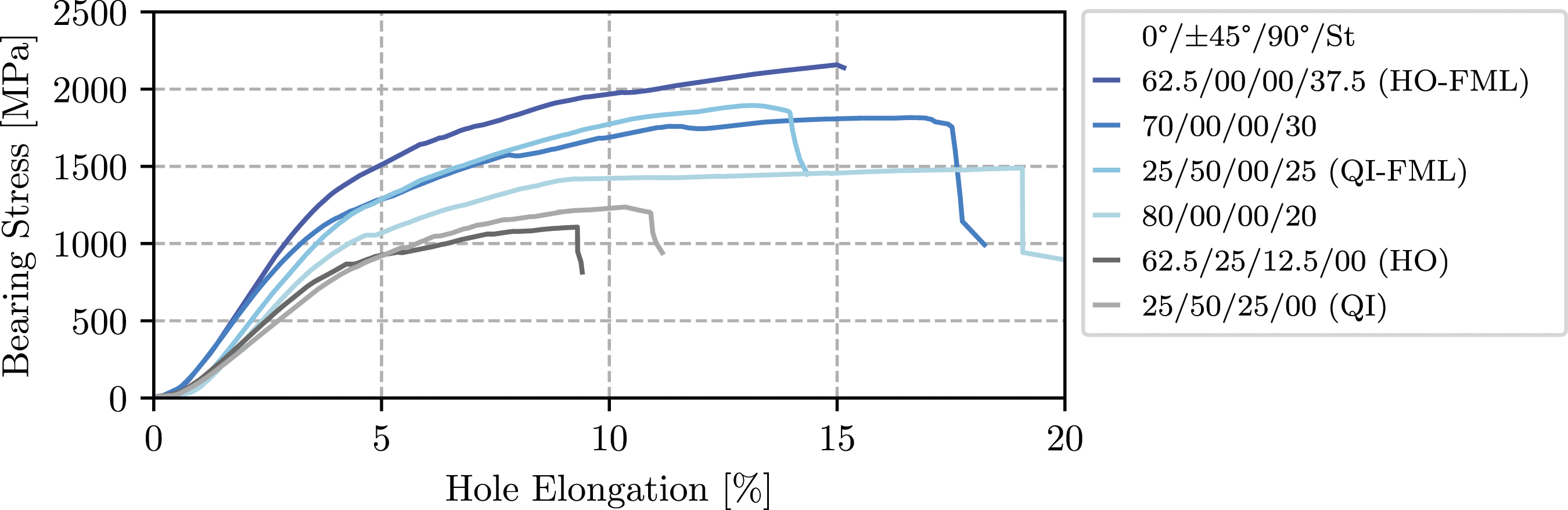
Regarding initial joint stiffness, increasing MVF leads to an increase of stiffness, therefore clearly indicating that the ply stiffness at the meso-scale influences the joint behavior at the macro-scale. As a result of the large number of 0° plies, the monolithic HO laminate has a higher initial joint stiffness compared to the monolithic QI laminate. Similarly, the joint stiffness of the FML increases gradually with increasing MVF, where within the MVF range of 20 % to 37.5 %, the initial stiffness seems primarily influenced by the steel content.
Concerning load-bearing capacity, i.e. strength, the behavior is not goverened solely by the metal content. Rather, the orientation of the composite plies within the FML noticeably influence the joint behavior. In general, increasing MVF tends to lead to an increase in the load-bearing capacity. However, the QI-FML in Figure 7 endures larger loads compared to the UD-CFRP-steel FML with 30 % MVF. Presumably, in the UD-CFRP-steel FML, kink bands propagate freely through 0° layers until encountering a steel ply. In contrast, the combination of 0° and ±45° layers in the QI-FML poses a greater obstacle to intralaminar damage propagation within the composite stack arrangement. This results in increased interfacial delamination and shear cracks, consequently elevating the energy required for damage progression and enhancing load-bearing capacity.
Bearing strength with varying MVF
Figure 8 presents BYS and BUS for varying MFV at LT. Three UD-CFRP-steel FMLs with MVF of 20, 30, and 37.5 % are considered. Additionally, the QI-FML strength with MVF of 25 % as well as the strengths of the monolithic QI and HO laminates are shown as a reference. The strength increase by hybridization regarding both BYS and BUS with respect to a monolithic QI reference laminate is indicated in the secondary and tertiary axis, respectively. Bearing strength depending on MVF at LT.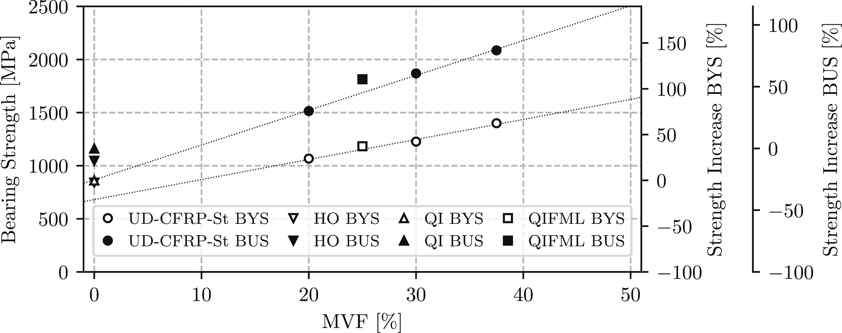
Considering the UD-CFRP-steel FMLs, a linear increase in bearing strength is observed for the mechanically relevant range of 20 % to 37.5 % MVF. By comparison to a monolithic reference laminate with QI stacking, hybridization with 20 %, 30 %, and 37.5 % steel leads to a strength increase of 23 %, 43 %, and 63 % concerning BYS, and 30 %, 61 %, and 80 % concerning BUS, respectively. Similar behavior is reported at RT by Fink 11 for CFRP-steel and CFRP-titanium FMLs. Even though the QI-FML with 25 % MVF strays from the strict 0° pattern seen in UD-CFRP-steel FMLs, it still lines up reasonably well with the overall trend, especially considering BYS. However, when it comes to BUS, the ealier mentioned advantageous effect through the mix of 0° and ±45° layers in the QI-FML is likely to cause the differences compared to the expected linear trend.
The linear correlation between MVF and bearing strength regarding both BYS and BUS at LT as well as RT offers significant advantages for preliminary design. With a relatively small amount of physical bolt-bearing tests, fundamental relationships between bearing strength and MVF for a hybrid material system can be established. This comprehension enables an initial approximation of the necessary MVF to attain the required joint strength. Utilizing this approximation, a limited range of configurations for local metal hybridization can be explored subsequently in more detail.
Bearing strength with varying joint geometry
The preceding sections have demonstrated that the strength increase observed in monolithic laminates due to hybridization at RT11,8,9 extends to LT. An additional advantage of metal hybridization is stated to be a decrease in minimal required edge-distance or edge-to-diameter (e/d) ratios and width-to-diameter (w/d) ratios.11,22 This fact allows for smaller distances between fasteners in multi-fastener joints, thereby increasing the efficiency of the joining area.
Fink
11
and Both
9
report that the minimum recommended w/d ratios in composite bolted joints decrease from 4-5 to 3 in a CFRP-steel or CFRP-titanium FML. Studies by Hundley
4
suggest that the minimum e/d ratios can be reduced from 3 in composite joints to 2 in CFRP-titanium FMLs. In an attempt to verify if these observations extend to LT levels, bolt-bearing tests are conducted with reduced e/d and w/d ratios. Therein, starting from e/d = 4 and w/d = 7 as recommended in AITM 1-0009, the ratios are gradually decreased to e/d = 1.5 and w/d = 2, respectively, as depicted in Figure 9. Variation of e/d and w/d ratios in monolithic QI and HO laminates as well as their respective hybridization (QI-, HO-FML) at LT; Failure types: bearing (B), net-section (N) and shear-out (S).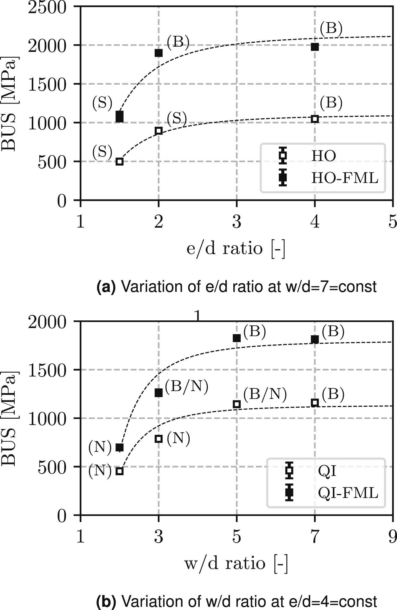
In brief, QI laminates are more prone to net-section failure as a result of the lower tensile strength associated with the lower fraction of 0° plies, while HO laminates generally tend to fail in shear-out mode resulting from the large number of 0° plies in combination with the limited amount of 90° plies providing minimal transverse strength. At the same time, reducing the w/d ratio generally promotes net-section failure of a bolted joint, while low e/d ratios tend to result in shear-out failure. In conclusion, and in order to tackle the most critical cases for the QI and HO laminates, the variation of w/d ratios is conducted for the QI and QI-FML, while the variation of e/d ratios is applied to the case of hybridizing the HO laminate.
In Figure 9(a), the BUS of the HO and HO-FML at LT is depicted for varying e/d ratios at a constant w/d ratio of 7. Both for HO and HO-FML, a substantial decrease in BUS is evident at e/d=1.5. For e/d ratios exceeding 2, an increase in the e/d ratio only has minimal influence on the BUS. Despite the BUS of the HO-FML consistently being approximately twice as high as the BUS of the monolithic HO laminate, hybridization in this instance does not lead to a reduction in the minimum recommended e/d ratio compared to the monolithic HO laminate, as the qualitative behavior of both material systems remains identical. Regarding the failure types, hybridization slightly extends the bearing-type failure to smaller e/d ratios compared to the monolithic HO laminate.
Figure 9(b) presents the variation of w/d ratios for the monolithic and hybrid QI laminates. For illustration purposes, the failure type of the QI-FML are shown in Figure 10. Analogous to the variation in edge distance, reducing the specimen width does not result in a qualitative change in strength behavior. For both QI and QI-FML, the minimum recommended w/d ratio appears to be around 4-5. This observation deviates from results reported by Fink.
11
However, Fink’s determination of the minimum w/d ratio is based on UD-CFRP-steel FMLs with 30 % MVF. In comparison to the present QI-FML, resistance against net-section failure is much higher in those laminates due to 5 % more MVF and, more significantly, a greater proportion of 0° plies (70 % as oppose to 25 % 0° plies) with high tensile strength. This observation emphasizes the need to discuss metal hybridization with respect to the specific basis laminates, rather than a generic consideration on the basis of UD-CFRP-steel FMLs. Additionally, the common assumption that pitch distances can be reduced by hybridization of CFRP laminates in9,11,8 is challenged. This assumption is deemed not universally applicable but rather true for specific laminate types, such as UD-CFRP-steel FMLs. A more comprehensive study, incorporating different basis laminates and various degrees of hybridization, can provide a more detailed insight into the potential for reducing minimum pitch distances through metal hybridization. Failure pattern in QI-FML after testing at LT. (a) QI-FML with w/d=2 (net-section). (b) QI-FML with w/d=3 (combined bearing/net-section). (c) QI-FML with w/d=5 (bearing).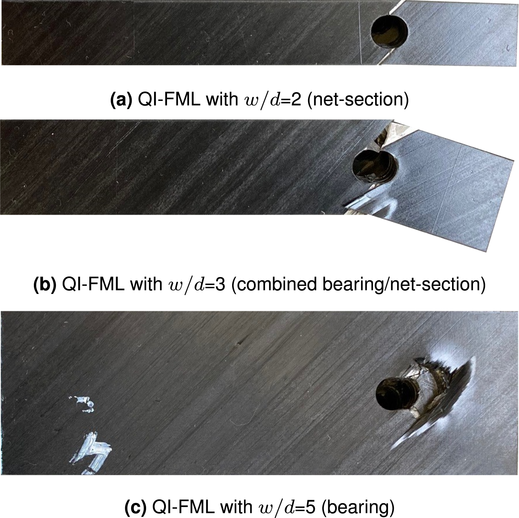
Damage analysis
After an analysis on macro-scale with a focus on load-displacement curves, bearing strength and failure modes, the present section deals with a detailed analysis of the damage mechanisms that are active on meso-scale. Thus, in an attempt to better understand the onset and propagation of damage in monolithic and hybrid laminates at LT, bearing specimens are investigated at varying load levels, namely 0.5 %, 4 % and maximum hole elongation. Ultrasound scans are used for the assessment of the total damaged area, whereas fractography by means of microscopy of the bearing plane is conducted to study the failure patterns within the laminates.
Figure 11 shows C-scans of the bearing specimens loaded to the aforementioned target hole elongations. While C-scans of the monolithic CFRP specimens are taken in reflection mode, FMLs are inspected in through transmission mode by using an additional receiver due to the different acoustic impendace between CFRP and steel. The C-scans show planar defects such as delaminations, voids and cracks normal to the propagated pulse. Since the type of defect cannot be differentiated, the C-scans are used for a qualitative analysis of the shape and size of the damaged area. Ultrasound C-scan images (CFRP: reflection mode, FML: transmission mode) of bearing specimens at different levels of permanent hole elongation.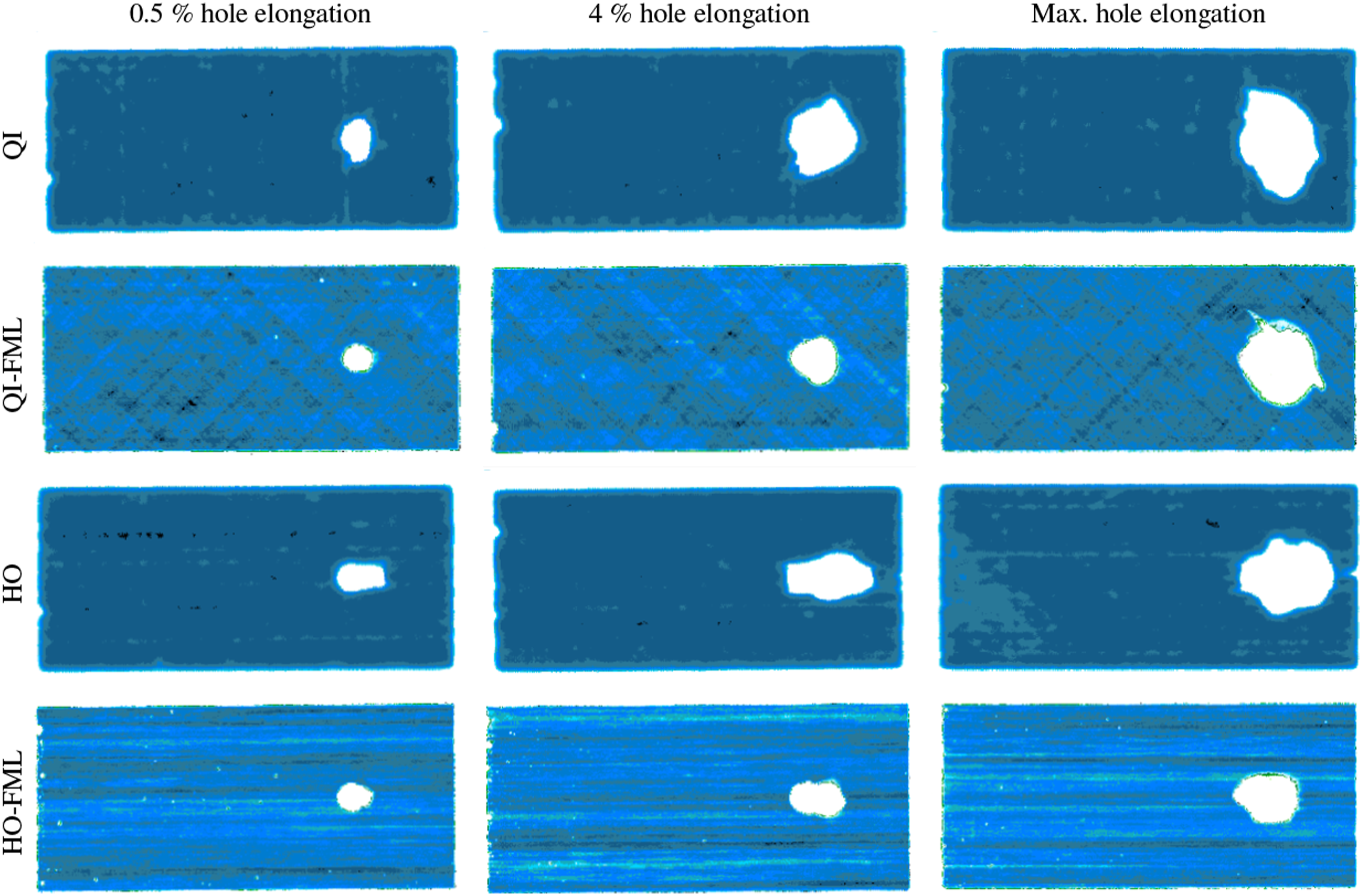
Examining the monolithic laminates reveals a notable difference in the spread of damage between the QI and HO laminates. The QI laminate shows significant expansion of the damaged area in both the loading and lateral directions, whereas the HO laminate displays a more directional damaged area with less lateral and more longitudinal expansion. Despite both QI and HO laminates showing an increase in the total damaged area with hole elongation, the pattern of the damaged area remains consistent. In FMLs, the damage pattern observed in the monolithic laminates is reflected in the QI- and HO-FML, respectively. The former exhibits more lateral damage, while the latter is characterized by a more directional pattern with primarily longitudinal expansion.
Comparison of the damaged area in both monolithic and hybrid laminates is conducted at load levels equivalent to 0.5 %, 4 %, and maximum permanent hole elongation. It should be noted that 0.5 % and 4 % permanent hole elongation essentially represent BYS for all laminates and BUS for the monolithic QI and HO laminate, respectively (see Figure 4). A direct comparison of the C-scans reveals that hybridizing QI and HO laminates results in significantly smaller damaged areas at 0.5 % and 4 % permanent hole elongation, highlighting the beneficial impact of metal hybridization on damage spread. Comparability of C-scans at maximum hole elongation is somewhat limited due to the fact that the states represent different levels of permanent hole elongation: approximately 8 % (QI), 12 % (QI-FML), 6 % (HO), and 10 % (HO-FML). Nevertheless, even under these for the FMLs unfavorable basis for comparison, the FMLs exhibit similar (QI-FML) or notably smaller (HO-FML) damaged areas compared to their monolithic counterparts, despite experiencing much larger permanent hole elongations and significantly higher loads.
Following the initial assessment of the damaged areas based on ultrasound scans in Figure 11, Figures 12 and 13 focus on the damage mechanisms in monolithic and hybrid laminates at LT. The figures show the fracture plane for x(y = 0) in Figure 2, i.e. the area where the bolt pushes on the laminate. Due to the lack of literature on on the effects of low temperature on damage mechanisms in FMLs, especially for CFRP-steel, the current analysis first focuses on verifying whether the damage mechanisms observed in the monolithic CFRP laminates (QI, HO) align with the observations from existing literature. Subsequently, the damage mechanism in the CFRP-steel FMLs (QI-FML, HO-FML) are analyzed and compared to the RT case reported by Fink,
11
in order to understand similarities and differences in damage patterns due to temperature. Microsections of the bearing plane before loading. (a) QI. (b) QI-FML. (c) HO. (d) HO-FML. Microsections of bearing specimens along the bearing plane at varying levels of permanent hole elongation at LT (bolt displacement from left to right).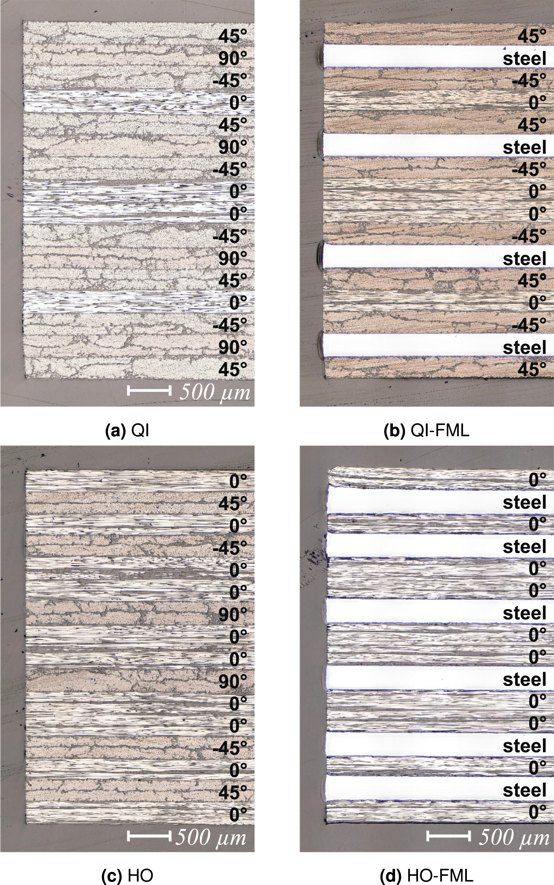
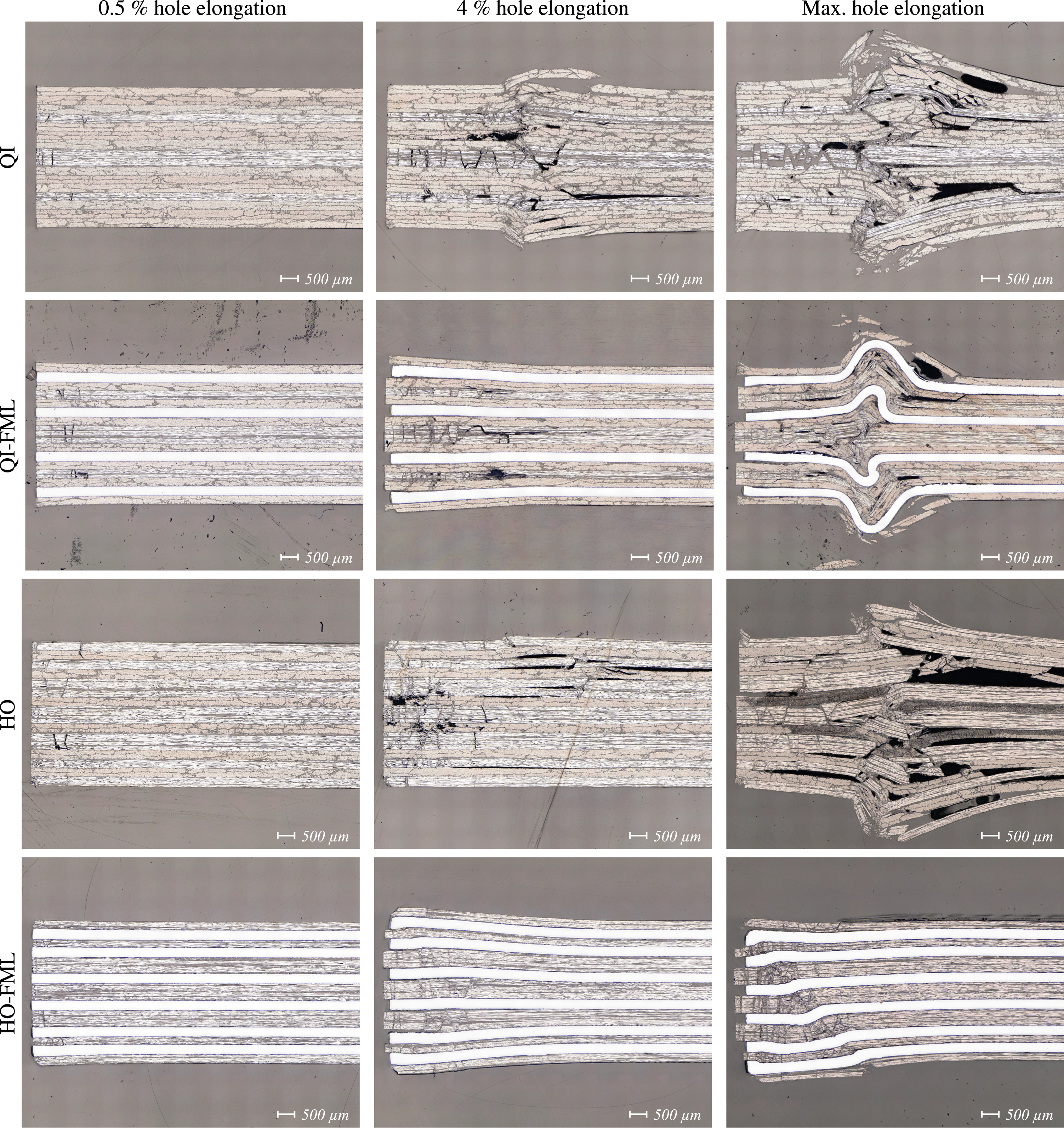
As a reference, Figure 12 presents microsections at the bolt hole of pristine specimens prior to loading that are sliced along the bearing plane. In contrast, Figure 13 shows microsections along the bearing plane of specimens that are loaded to 0.5 %, 4 %, and maximum permanent hole elongation. It should be noted that these specimens are the same ones that were previously examined by ultrasound in Figure 11.
The top row in Figure 13 illustrates the damage behavior in the QI laminate. Damage in the QI laminate is initiated through fiber kinking primarily in the 0° plies. At 0.5 % permanent hole elongation (BYS), mostly fiber kinking without further damage patterns is visible. Towards 4 % permanent hole elongation (approximately BUS), extensive fiber kinking in the 0° plies leads to matrix shear cracks in the adjacent ±45° plies, while only limited damage in the form of a few micro-cracks are visible in the 90° plies. Similar to literature reportings,33,11 the lateral support provided by the washers largely contains the damage. However, beyond the washer region, substantial delamination, wedge-type splitting, and lateral bulging of the top and bottom plies in the laminate are observed. At maximum hole elongation (approximately 8 %), the damage pattern remains similar in nature but is more pronounced, indicating a loss of load-bearing capacity in the laminate.
In the third row in Figure 13, the HO laminate is shown. Compared to the QI laminate, damage in the HO laminate is characterized by more pronounced fiber kinking in the 0° plies at 0.5 % hole elongation (BYS). Plus, the kink-bands appear to induce matrix shear cracking in the adjascent ±45° plies. Only little damage can be seen the 90° plies. At 4 % permanent hole elongation (approximately BUS), a wedge-type failure pattern is created by extensive fiber kinking and matrix failure including some delamination. Under the washer area, damage is mostly contained, however, outside the washer area, lateral bulging of the laminate due to the crushing of failed plies can be seen. In addition, severe delaminations extending up to 15 mm into the bulk laminate is observed. At maximum permanent hole deformation (approximately 6 %), severe damage outside the washer region results in lateral bulging and consequently to a loss of the load-bearing capacity in the HO laminate.
In conclusion, the damage mechanisms observed in the QI and HO laminates at LT involve fiber kinking, matrix shear cracks, and delamination. Despite significant damage accumulation in the washer area, bearing failure is initiated by laminate crushing and lateral bulging outside this region, aligning well with findings reported in the literature.32,38,33
In row two in Figure 13, damage in the QI-FML is presented. At 0.5 % permanent hole elongation (BYS), fiber kinking in the 0° plies is present. There is no visible damage in the ±45° plies. Delamination is present in between composite and steel plies near the hole much earlier than in the monolithic laminates, presumably due to the difference in interface strength and thermal residual stress state in the FML39,36 in combination with the stress concentration at the bolt hole. 40 At 4 % permanent hole elongation, substantial fiber kinking and matrix shear cracking as well as delamination at all CFRP-steel interfaces under the washer area is observed. Damage accumulates primarily in the region under the washer area. While wedge-type damage is present in the QI laminate at this load level, the steel plies in the QI-FML prevent the formation of the wedge-type damage pattern. At maximum permanent hole elongation (approximately 12 %), substantial damage accumulation is observed in the CFRP plies under the washer area. Furthermore, the steel plies experience large plastic deformation. However, despite the outward bulging of the laminate outside the washer area, bearing failure in the QI-FML occurs at significantly higher bolt loads and larger permanent hole elongation compared to the monolithic QI laminate. This is attributed to the fact that the FML can undergo extensive plastic deformation and contain large damage density in the CFRP plies between the metal sheets, thus resulting in larger energies dissipation for damage propagation to occur.
In the fourth row in Figure 13, the formation of kink bands can be seen in the 0° plies, thereby marking the initiation of damage at 0.5 % permanent hole elongation (BYS) in the HO-FML. Similarly to the QI-FML, the HO-FML also exhibits delamination between CFRP and steel layers near the hole edge. At 4 % permanent hole elongation, extensive fiber kinking in a zig-zag pattern is observed. This damage is accompanied by delamination between all CFRP-steel interfaces as well as some plastic deformation in the steel plies due to outward bending under the washer. At maximum permanent hole elongation (approximately 10 %), substantial damage accumulates in the composite plies in the washer area. However, failure of the joint results from kinking in the steel plies, accompanied by a wedge-type damage pattern, leading to a loss of stability and, consequently, a loss in load-bearing capacity of the HO-FML.
To summarize, damage in the QI-FML and HO-FML is initiated by the formation of kink bands in the 0° plies, which again result in matrix cracks in neighboring composite plies of different orientation. With increasing bearing load, substantial damage accumulates within the CFRP stacks and delamination is present at the CFRP-steel interfaces. Failure occurs as a result of significant plastic deformation and out-of-plane bending of the metal plies, which causes a loss of stability outside the washer area. It can be concluded that through the introduction of steel plies (i) composite plies are relieved, (ii) damage in the composite stacks is isolated and prevented from spreading in through-the-thickness direction, and (iii) additional stability in the out-of-plane direction is provided, thereby increasing the load-bearing capacity. With respect to BYS, the relief of composite plies due to the large stiffness of the steel sheets is dominatnt. Considering BUS, the capability of steel to undergo extensive plastic deformation as well as the containment of damage within composite plies by neighboring steel sheets are the dominant mechanisms that lead to an increase in bearing strength. These findings agree well with observations by Fink 11 for CFRP-steel FMLs at RT. When considering the effect of temperature, delaminations in FMLs are more pronounced at LT compared to RT and represent a significant contribution to the overall failure mechanism, similar to the behavior reported for monolithic laminates at LT. 33
Conclusions
An experimental study on the bolt-bearing behavior of CFRP-steel hybrid laminates is conducted. The study deals with low temperature effects in monolithic and hybrid laminates, the reinforcement effect through steel hybridization, effects from varying joint geometry, and additionally offers a detailed investigation on the fracture behavior of monolithic and hybrid laminates under bolt-bearing loading.
Decreasing testing temperatures leads to an increase in bolt-bearing strength in both monolithic and hybrid laminates. However, at LT, the monolithic laminates exhibit brittle behavior resulting in failure at relatively low hole elongations, while the hybrid laminates remain quasi-ductile sustaining bolt-loads at significantly higher deformation. This indicates an advantage of hybridization regarding damage tolerance.
While steel hybridization of the monolithic QI and HO laminates leads to a significant increase in bearing strength with respect to both BYS and BUS, the strength increase is less pronounced at LT compared to RT conditions. Presumably, the presence of thermal residual stresses in the FMLs could limit the full exploitation of material strength, which is an effect that would become more and more dominant with decreasing temperature. Further numerical analysis is necessary to verify this assumption.
For MVF between 20 - 40 %, the bearing strength increases linearly with increasing MVF at LT, which corresponds to observations at RT. 11 Therefore, design charts can be derived to facilitate the joint design. However, regarding recommendations with respect to minimum required e/d and w/d ratios, literature reports9,11,8 are challanged, as the reduction of minimum edge and width distances by hybridization is not generally true but largely depends on the laminate stacking, as is demonstrated by the QI- and HO-FMLs in the present study.
The damage mechanisms in the hybrid laminates differ considerably from the monolithic laminates. Regarding BYS, hybridization is associated with a relief of composite plies by the introduction of steel plies, an isolation of composite damage, and additional stability in out-of-plane direction, thereby increasing the load bearing capacity. Considering BUS, hybridization offers the advantages of extensive plastic deformation and containment of composite damage between metal plies, which leads to an increase of bearing strength. At both BYS and BUS, however, delamination at the CFRP-steel interface at LT are more pronounced than at RT, and represent a significant contribution to the overall failure behavior.
To conclude, the present results demonstrate that the favorable effect of hybridization on the bolt-bearing behavior of composites preveously observed at RT, also extends to LT conditions. However, the fact that the reinforcement effect by steel hybridization is less pronounced at LT compared to RT, raises the question whether thermal residual stresses in the CFRP-steel FML need to be taken into account, e.g. during numerical and analytical analysis.
Footnotes
Declaration of conflicting interests
The author(s) declared no potential conflicts of interest with respect to the research, authorship, and/or publication of this article.
Funding
The author(s) received no financial support for the research, authorship, and/or publication of this article.
Data Availability Statement
Data sharing not applicable to this article as no datasets were generated or analyzed during the current study.