
Abstract
This article presents a research into the development of novel Hybrid Laminates (HLs) prepared with the use of hot-pressing method. Two types of HLs are fabricated through the composite coating with different fiber amounts (40 and 50% wt.) of only one surface of 7075-O Al alloy substrate. Effects of the fiber contents of the thermoplastic composite in the hybrid structures are investigated with regards to the tensile and flexural properties. The influence of bending load applied from different surfaces on flexural responses is also evaluated. The tensile test results indicate that the increased fiber ratio slightly affects the failure load of composite layer in the HLs. On the other hand, the flexural strength decreases with the increasing fiber amount in the HLs whether the three-point bending is performed on the Al surface or the composite layer. Scanning electron microscopy (SEM) is used to study the fracture surfaces after the mechanical characterization. From the SEM observations, it has been realized that fiber/matrix debonding is the key failure mechanism during the tensile tests. The failure mode of both HLs is delamination in the PP composite at the tensile side when the bending applied from the Al layer.
Keywords
Introduction
Over the past decades, thermoplastic polymers are increasingly gaining favor as substitutive materials for non-recyclable thermosetting polymers.1,2 Among thermoplastics, PP polymers have been drawing a great deal of attention due to their low density, good chemical resistance, outstanding processability, high electrical resistivity, low manufacturing costs and reasonable flame resistance.3–6 These remarkable properties pave the way for the engineering applications of PP, especially in the automotive industry.7–10 Besides, these materials have widespread field of applications, from durable goods to electrical-electronic appliances.11,12 However, the disadvantages such as relatively inadequate mechanical properties, poor thermal and dimensional stability require the reinforcement of pure PP with organic/inorganic fillers.13,14 Herein, uniform dispersion of reinforced materials in polymer is very important for the composite material to have superior mechanical properties. 15
Thermoplastic composites are widely used in recent years because they have good impact toughness, promising specific strength, and shorter processing cycle in comparison to thermosetting composites.16–18 They show a great potential in daily life and several industries, such as automotive, transportation and aerospace.19–23 Glass fiber (GF) is one of the most commonly used reinforcements in the composites due to its low cost and relatively good mechanical properties.24,25 Nevertheless, thermoplastic composites have few drawbacks, for instance, poor impact resistance 26 and weak ductility properties by comparison with metal alloys.27,28 The need to overcome these drawbacks has resulted in hybrid composites that are known as Fiber Metal Laminates (FMLs). Glass fiber/metal laminates which comprise of alternating layers of aluminum (Al) alloy and fiber reinforced plastic composites with the trade name of GLARE were originally developed at Delft University.29,30 FMLs have good moisture and corrosion resistance, 31 high specific strength and stiffness, 32 good impact and fatigue resistance 33 and low density achieves lighter structures compared to conventional metals, which makes a great contribution to fuel efficiency. 34 Resulting properties of hybrid structure are highly dependent on the manufacturing history as well as the component properties.35,36 There are various constituents utilized for the fabrication of FMLs. However, FMLs with thermoplastic matrix have gained considerable attention due to the brittleness of the thermoset layers, their low elongation features, and the complexity of their production process.37,38 Therefore, a new generation of the FMLs based on the Al alloy (7075) in combination with PP composites is a conspicuous alternative.
There is a growing interest for developing lightweight structures from both academic communities and the industrial platforms upon the rapid advance of the aerospace and automotive industries. 39 Al alloys have a great contribution in the development of these sectors. 40 Especially in the automotive industry, one of the primary concerns for manufacturers is to meet requirements on fuel consumption, CO2 emissions and vehicle safety through the lightweight structures.41–43 To this end, ultra-high strength materials and their HLs can be considered as an alternative to replace a portion of heavier structural components. In FMLs, it is important to provide the appropriate combination of metal and composite layers in order to achieve the desired features. 7xxx series alloys are one of the most prominent candidates for lightweighting of the structural components. Among Al-Zn-Mg-Cu alloys, 7075 Al alloys are widely used as structural materials owing to their relatively small density and excellent mechanical properties such as the high specific strength and toughness.44,45 The higher formability of these alloys in O-temper condition provides practical and common industrial applications. 46 The novel HLs based on 7075 Al alloy can significantly ensure a weight reduction. In addition, composite layers in hybrid structures can provide high resistance to corrosion as a barrier in the corrosion process. 47 Furthermore, polymer-metal layered structures are increasingly gaining favor in enhancing the impact response of metallic substrates. 48 For asymmetrical laminates, the methods used to evaluate the mechanical properties of symmetrical structures are not fully applicable and should be studied carefully. Residual stresses that may occur due to the different coefficients of thermal expansion (CTE) of the metal and polymer layers during the fabrication process and that may cause undesired early damage should also be considered. 49
FMLs composed of innovative constituents have been developed and investigated after high-strength alloys and composite materials become more widespread. However, most of the studies generally focused on the mechanical properties,50–54 especially tensile response,55,56 interface characterization57–60 and impact behavior61–64 of FMLs with various stacking sequences of sandwich configuration. Literature data from the research into the mechanical characterization of the HLs with composite joined on one side of a metal are quite scarce. Yu-Chien Ho and Jun Yanagimoto 65 studied the punching of multilayer carbon-fiber-reinforced plastic (CFRP) laminates and CFRP/metal hybrid composites. Three different metals (Al alloy 6061, magnesium alloy AZ31 and advanced high-strength steel SPFC980) were used to develop hybrid composites with the CFRP laminate. The effect of the unidirectional (UD) prepreg size on the punch-shear load, punching resistance and the action of shearing was evaluated. They investigated the punch-shearing of a through-hole in laminated composites through a force analysis. It was found from their experimental results that the interface bonding of punched CFRP/SPFC980 was more reliable than the CFRP/A6061 and CFRP/AZ31. Nohjun Myung et al. 66 evaluated the mechanical properties and low-cycle fatigue behavior of woven glass fiber plastic (GFRP) laminated on one side of an AA6061-T6 flat plate. One, three, and five plies of GFRP coating were utilized for the investigation of effects of the number of lamination plies on the mechanical properties in terms of the tensile behavior. The mechanical test results demonstrated that the maximum load of the GFRP-Al samples significantly increased through the augmenting thickness of the GFRP layer. Fatigue strength also increased, although not proportional to the GFRP thickness. V.S. Balakrishnan et al. 67 investigated the flexural and impact response of Fiber Reinforced Plastic (FRP)-metal HLs by way of the three-point bending and low-velocity impact tests, respectively. The thermoplastic-based glass/PA-6 FRP on steel surface using the press-forming technique and thermoset based glass/epoxy FRP using the vacuum assisted resin transfer molding process were developed. As a result of the mechanical tests, PA-6 showed better bonding to the 22MnB5 steel than epoxy. Heat-treated steel showed better flexural performance by comparison with the steel without heat treatment. Better impact response was also obtained in the FRP-metal HLs with PA-6. Taking into account all of these works, there are no research on AA7075-O based HLs with thermoplastic composite, to the best of author’s knowledge.
This paper aims to investigate the influence of the different fiber percent (40 wt. % and 50 wt. %) of the composite on the mechanical properties of hybrid layers. Al alloy (7075) in the annealed condition is used as the metallic constituent and 40 and 50% glass fiber reinforced PP composites are used as the composite layers. Mechanical characterization of the HLs is comparatively studied among themselves in terms of the uniaxial tensile and flexural properties. Moreover, fracture surfaces of the HLs are evaluated to assess the failure mechanisms of the hybrid composites. One of the objectives of this research is also to provide a cost-effective solution with good adhesion mechanisms between the thermoplastic composite and the metallic layer. For this purpose, glass fiber-reinforced PP composite and 7075-O Al alloy are joined through hot pressing without any kind of adhesive.
Experimental procedure
Materials
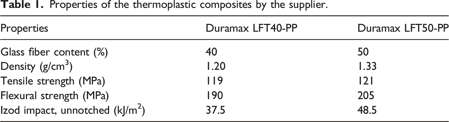
Properties of the thermoplastic composites by the supplier.
Preparation of thermoplastic composites
The E-glass reinforced thermoplastic composites were prepared through a Fontijne Presses - LabEcon60 Laboratory Platen Press with a maximum closing force and maximum temperature of 600 kN and 300°C, respectively. Load sensitive rectangular platen having the dimension of 400 × 400 mm2 was used to compress the granules and to fabricate the panels. First, long glass fiber reinforced homopolypropylene composite granules are homogeneously distributed into a mold with 2-mm thickness for the production of composite panels. Considering the granule densities and the mold size (350 × 350 × 2 mm3), 294 g and 326 g of fiber reinforced PP were used for GF40-PP and GF50-PP composites, respectively. Herein, it should be noted that polytetrafluoroethylene (PTFE) films were placed to bottom and upper surfaces of the mold so as to prevent sticking of the composite panels to pressing plates and for easy removal of the panels. In this way, final plates with desired dimensions were obtained. Thereafter, the mold was kept inside the hot press at 190°C for 50 min with 100 kN force, followed by a cold press for 16 h at a constant force to avoid warpage failure. Finally, the thermoplastic composites with different fiber contents were removed from the molds. Unsurprisingly, final thickness of the composite panels was noted as 2 mm.
Fabrication of hybrid laminates
Before manufacturing of the HLs, mechanical and chemical treatments were applied to the 7075-O Al alloy to provide strong bonding between the metallic parts and the composite panels of GF-PP/metal HLs. As a beginning, the AA7075-O plates were cleaned through acetone to remove probable impurities and dirt on the surfaces and then abraded with #400 grits emery paper in an orderly manner. Afterwards, the plates were rinsed with running water and finally were allowed to dry at a room temperature. After the mechanical treatment, AA7075-O plates were immersed in hydrochloric acid (HCl) aqueous solution with 11% volumetric concentration at a room temperature for 30 min, then rinsed with running water and the plates were allowed to dry out at room temperature. Lastly, alkaline etching by 10 wt. % sodium hydroxide (NaOH) aqueous solution was performed on the treated plates for 2 min at 70°C. The plates were washed again with tap water and dried at an ambient temperature. These chemical processes allow the formation of a porous oxide layer and elevated surface roughness on the Al alloy surfaces, which cause the interfacial bonding to enhance.69,70 It is known that the Al surface roughness plays an important role on the interface bonding strength. 71 On the other hand, no treatment has been applied to the thermoplastic composites that compose the hybrid structures.
In this study, the HLs were developed using a hot-pressing connection, where the thermoplastic composites with different fiber amounts were separately stacked with the AA7075-O plates. By using a hot press, the glass fiber-reinforced PP composites. By using a hot press, the glass fiber-reinforced PP composites were successfully joined with the cleaned and surface treated Al alloy plates without using any kind of adhesive material as shown in Figure 1. In the production process, mechanically and chemically treated AA7075-O plates were used as a substrate and placed in a mold of appropriate height. Then, the composite panels were smoothly placed on the Al plates. PTFE films were placed to bottom and upper surfaces of the mold for easy removal of the HLs as in the thermoplastic composite preparation. Thereafter, the mold was kept inside the hot press at 190°C and the force of 100 kN was applied. The mold was kept in the hot press at this force for 30 min. Finally, the HLs were de-molded after a cold pressing for 16 h within the pressing plates at a room temperature. The final thickness of the AA7075 based HLs was 5.1 mm. Manufacturing procedures of GF-PP/metal hybrid laminates.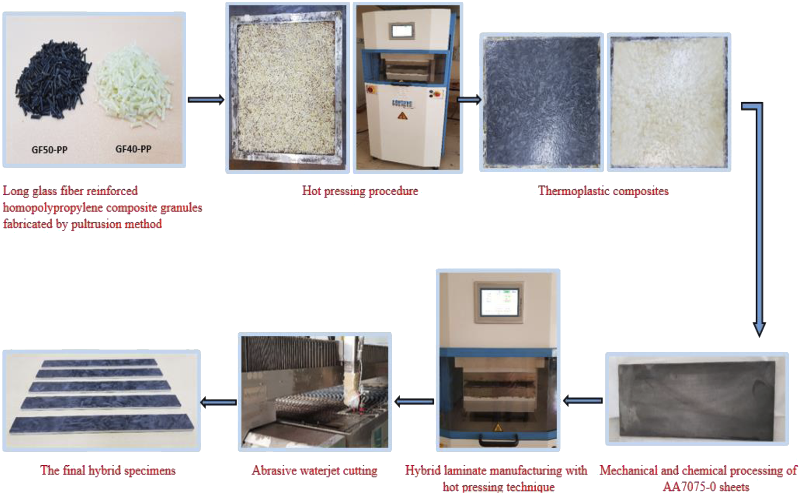
Characterization of mechanical properties
Tensile properties and flexural responses of the hybrid composites were investigated according to the procedure of ASTM D3039
72
and ASTM D790,
73
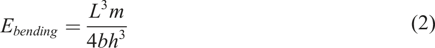
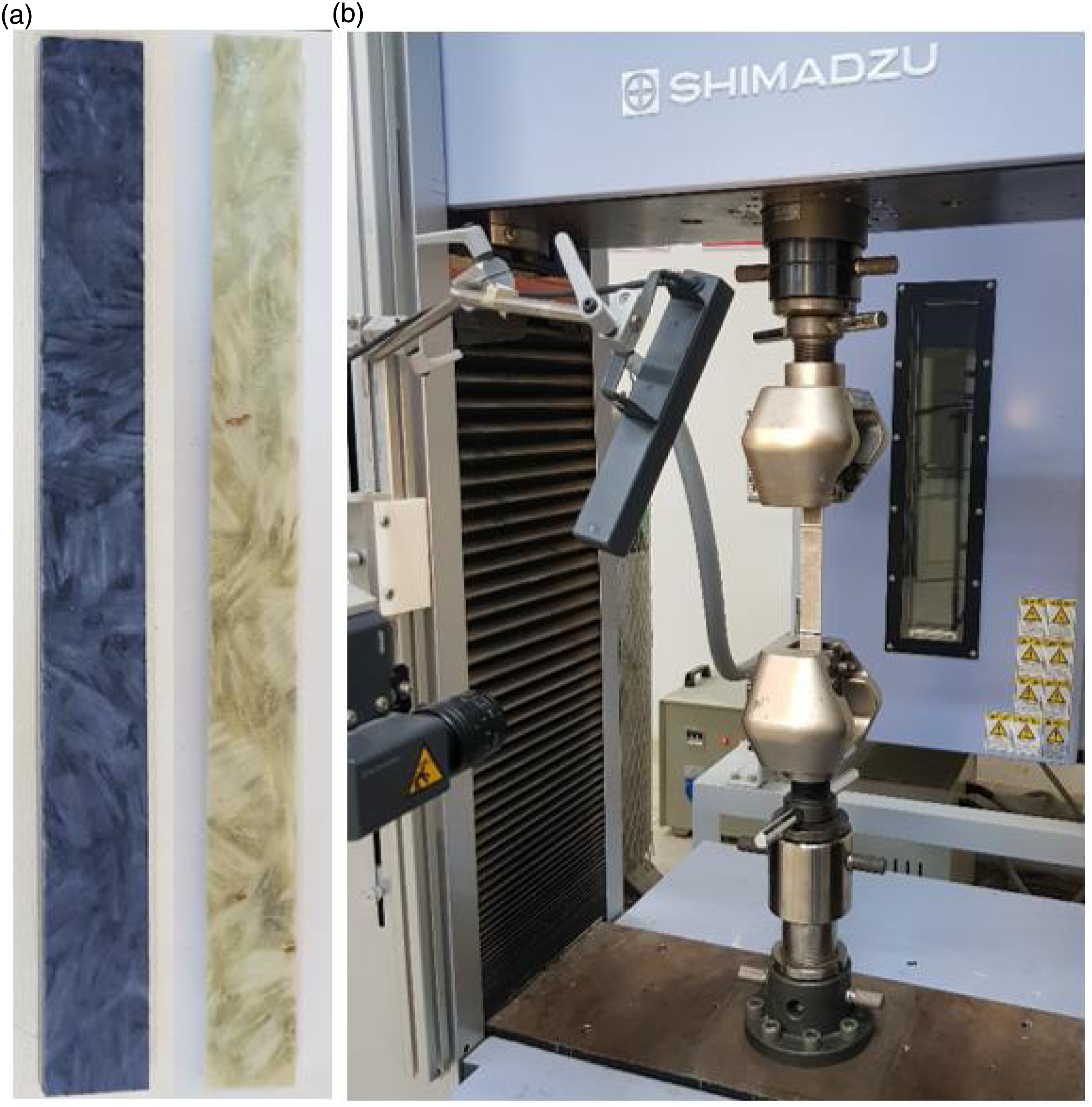
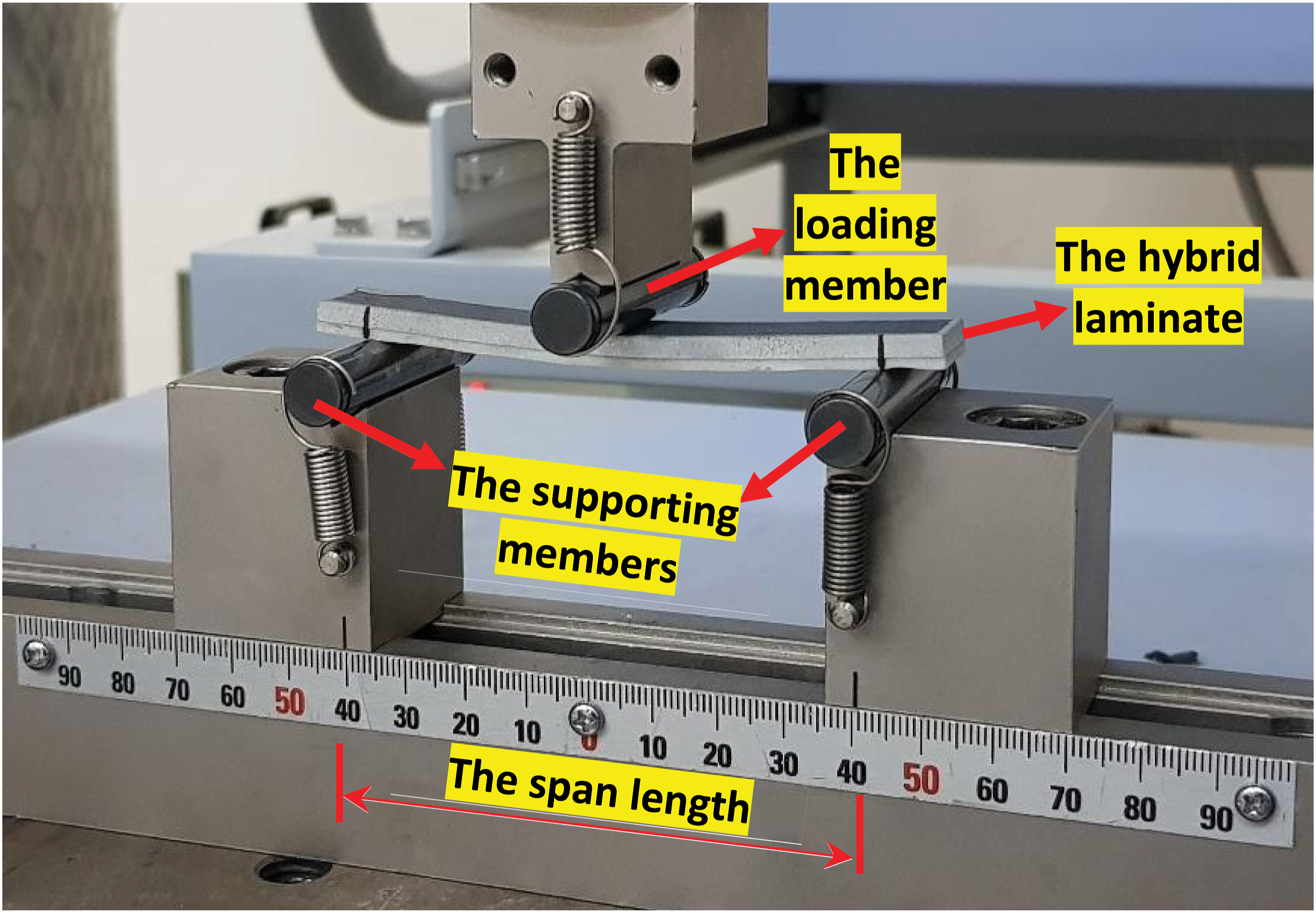
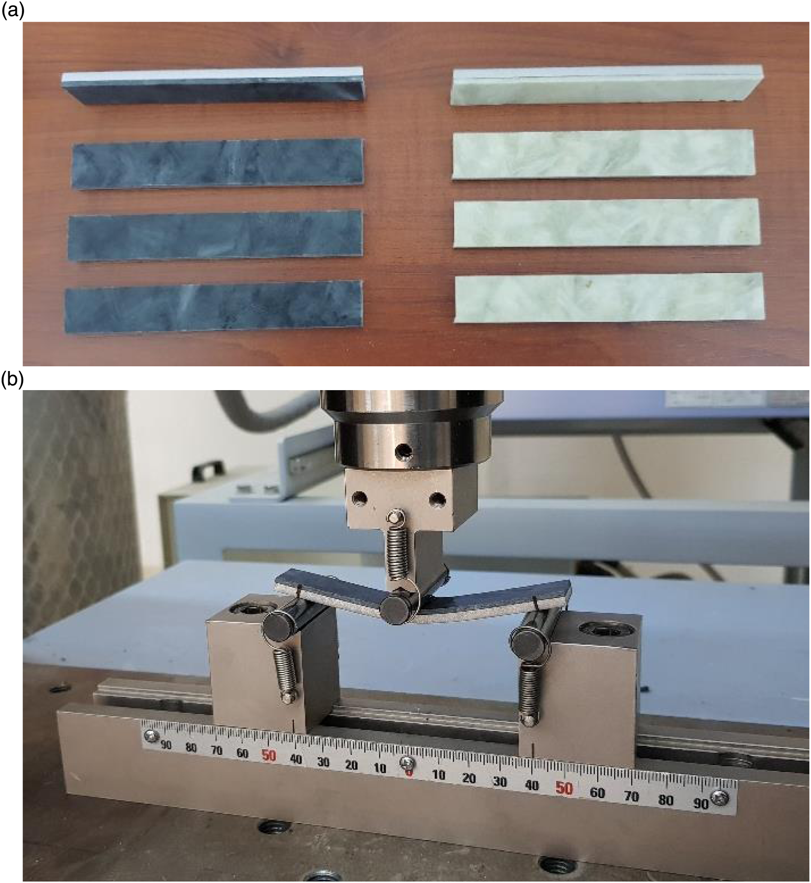
respectively. All samples for the mechanical characterization of the HLs were cut by abrasive water jet. For the uniaxial tensile tests, the final HLs were sectioned into the rectangular shaped specimens with 200 mm × 20 mm dimensions. Figure 2 shows the tensile test specimens before and during the experimental tensile test set up. The tensile tests were conducted at a room temperature at the constant crosshead speed of 1 mm/min on a Shimadzu AG-X (100 kN) universal Testing Machine with a 100 kN load cell. The tensile tests were repeated four times until the specimens completely damaged and average results were reported. Strain for each sample during the testing was also measured using a digital video extensometer TRViewX (gage length of 100 mm). The strain measurements for both hybrid structures were taken from the metal surface. Flexural properties of the hybrid samples were determined using a three-point bending method on the Shimadzu AG-X (100 kN) using the test fixture shown in Figure 3. In this test, radius and length of the loading member and its support members were 5 ± 0.1 mm and 50 ± 0.2 mm, respectively. The tests were conducted at a constant loading rate of 2 mm/min until a clear failure observed in the hybrid structures and the size of specimens was 100 mm × 15 mm. The test specimens before and during the testing process are demonstrated in Figure 4. The bending load was applied at the mid span of the specimens and the corresponding values of the load and deflection were reported. The specimens were removed from the test machine when the displacement increases to 30 mm. To examine the effects of bending on different surfaces owing to the asymmetrical structure, the tests were carried out by applying loads from both sides of each hybrid composite. Within the research, the support-span length of 81.6 mm was used to satisfy the recommended a span (L) to depth (h) ratio of 16:1. Four specimens were tested to ascertain the effect of manufacturing method and test conditions variability. The flexural strength (σflexural) and modulus (Ebending) were respectively calculated using the formulas given below Tensile tests: (a) samples before, (b) during the testing. Details of three-point bending test fixture installed on the testing machine. Flexural tests: (a) samples before, (b) during the testing.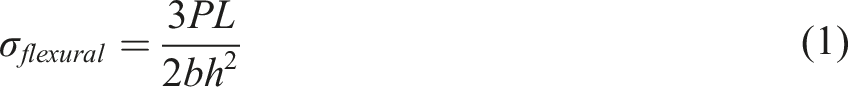
Fractography
Fractured surfaces of the GF-PP/metal HLs with different fiber contents after the uniaxial tensile tests and three-point bending method were scrutinized through a scanning electron microscopy (SEM) FEI Quanta 250 FEG operated at a room temperature at 3 kV in order to evaluate failure mechanisms of the specimens. A thin gold/palladium (Au/Pd) layer was coated on fracture surfaces of all samples to prevent charging and to improve image quality.
Results and discussions
Tensile properties
It is known that the tensile properties of hybrid structures are highly dependent on properties of each component that achieves the structure and the interface stability.
74
The representative tensile force-strain curves of the HLs with the composite fiber contents of 40 wt. % and 50 wt. % are demonstrated in Figure 5. Due to the stress irregularities caused by the reduction of area in the HLs after failure of the composite coating, the force-strain curves are utilized for evaluation. According to the figure, the hybrid structures show similar trend except for the response where the composite is damaged. After the composite layer is failed, the Al carries the tensile load. The thermoplastic composite layer breaks below yielding point of the AA7075-O since the tensile strength of the PP composite is lower than that of the AA7075-O. Herein, it should be pointed out that the force causing the yield was determined by the offset method (0.2% proof stress) since yielding point of the Al alloy could not be clearly defined during the tension tests. Figure 6 shows the stress-strain response of the base metal (7075-O Al alloy). Representative tensile force-strain curves of the HLs. Stress-strain curves of the 7075-O Al alloy.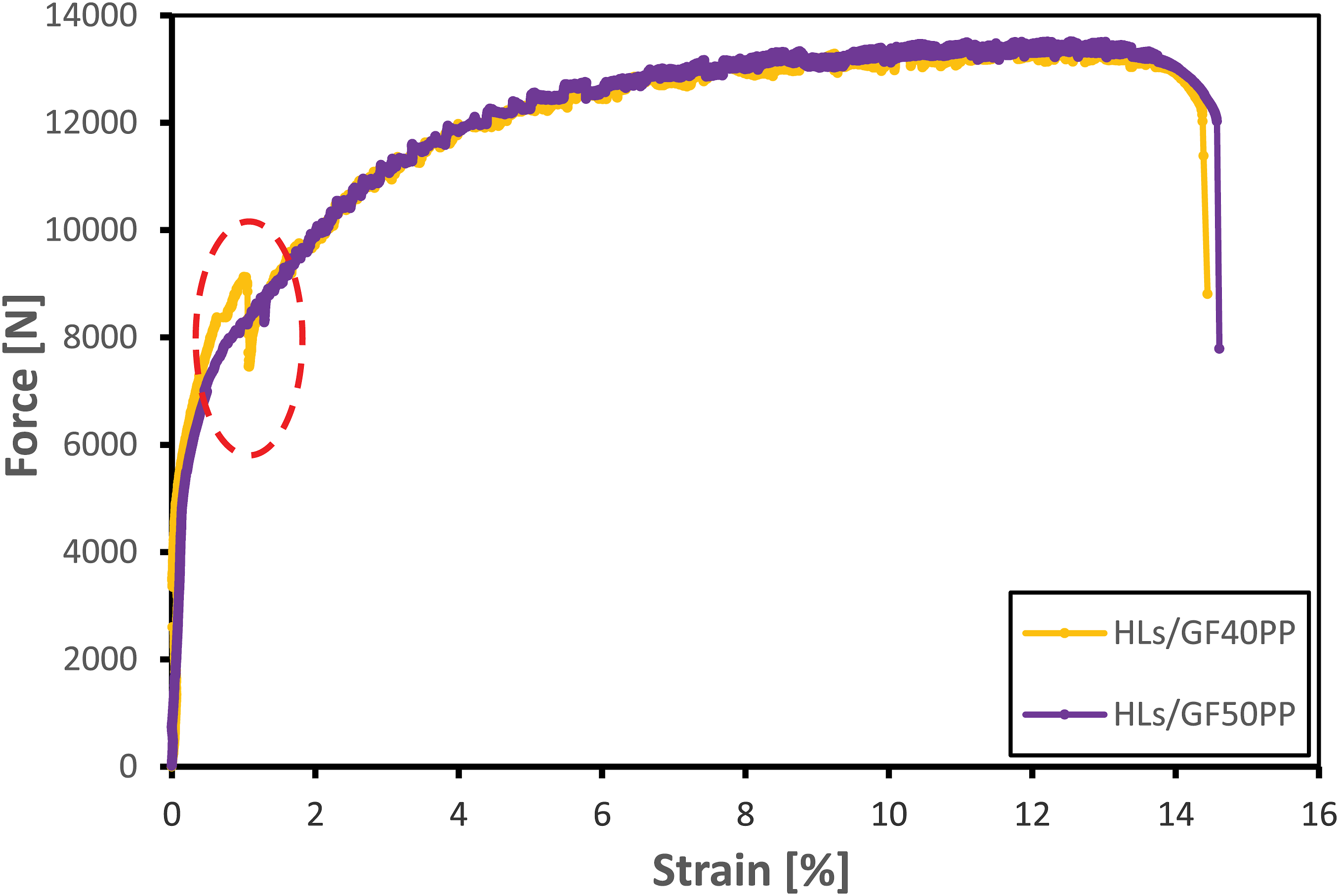
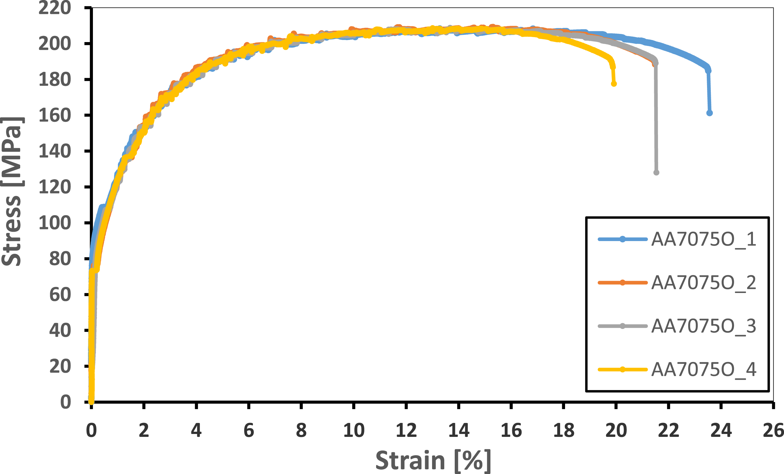
Considering the curve for the GF40-PP HLs, both the composite and metallic layers behave elastically up to a certain load causing the onset of damage within the PP composite. After this point, the sudden load drop is observed with progressive composite failure. Then, only the metal layer carries the load subsequent to the complete fracture of the composite layer. The composite experience lateral failure in the gauge area up to its catastrophic failure, which marked with dashed red line in the graph, as the Al alloy layer continues to deform elastically within that period. After this stage, the 7075-O Al alloy begins to be subjected to a stress above the yield point as a result of the significant cross-section reduction in the structure. Hereby, the Al alloy deforms plastically due to the breakdown of the integrity of the hybrid structure. Brittle fracture with complete separation of the composite layer in two pieces occurred after 8000 N for all samples. The average of the fracture loads and equivalent strain values of the composite layers was calculated as 8321.73 N and 1.1%, respectively. After the composite layer is completely failed and unable to bear tensile load, the remaining response represents a similar behavior in terms of the tensile strength to that of the AA7075-O base metal. On the other hand, it is seen that the hybrid structure shows a lower elongation at break than the base metal. Unlike the base 7075-O Al alloy, the HLs subsequent to the failure of composite exhibit an embrittlement without a pronounced necking after the maximum stress levels. This behavior can be explained by the fact that stress corrosion cracking (SCC) susceptibility of the 7075 Al layer after the chemical treatment and manufacturing procedures of the HLs.
75
Acidic solutions may induce corrosion attacks with pitting morphology on the Al surface not visible to the naked eye.76,77 Possible localized corrosion and pitting can influence the mechanical properties of the material and thus lead to a premature failure through a critical external stress.
78
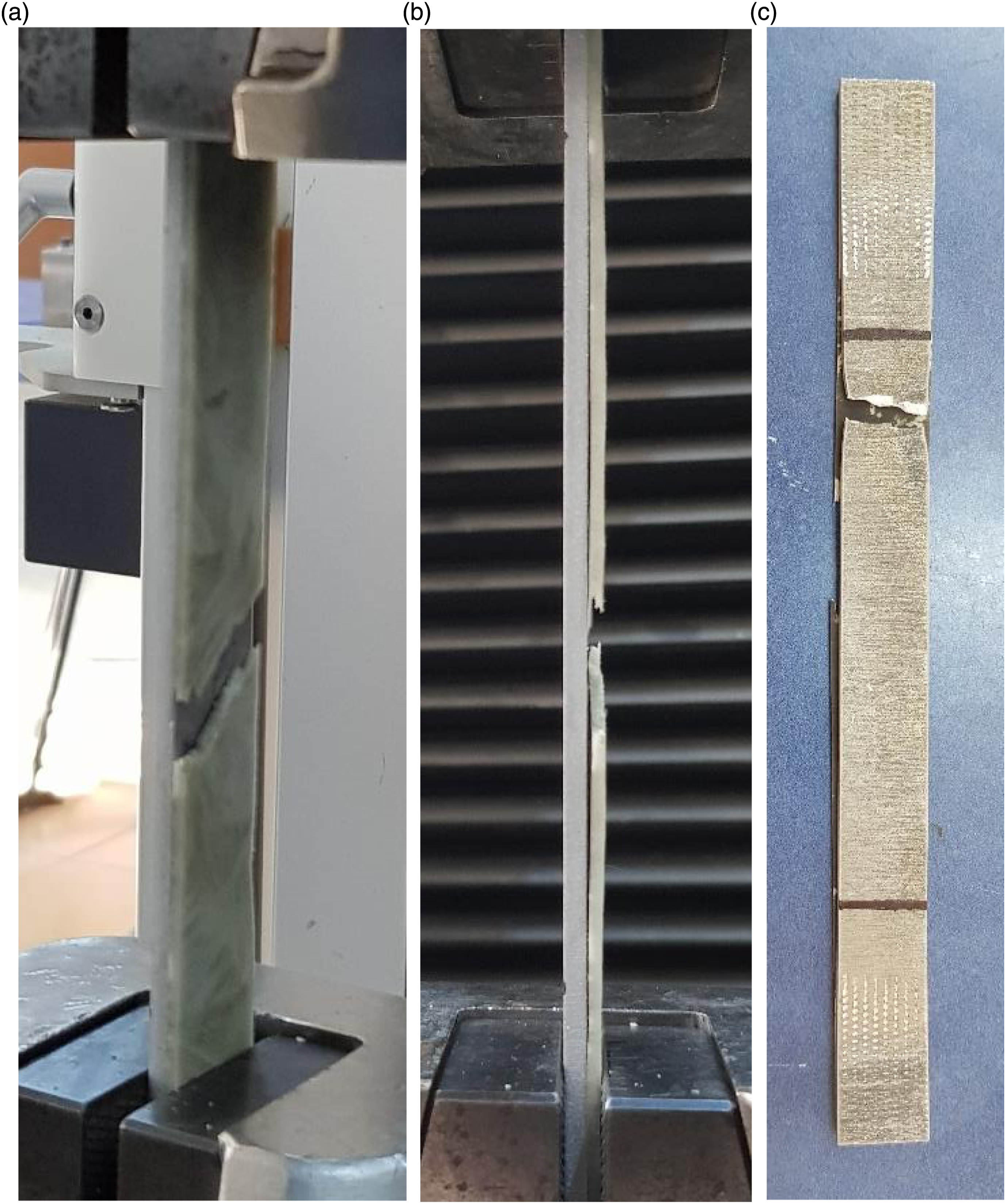
The significant decrease in failure strain of the HLs with GF40PP composite by about 33.2% can be ascribed to these effects. Figure 7 exhibits a failure location of the composite layer that was completely damaged with the signs of interfacial debonding during the test and the AA7075-O after the tensile test. Other samples were also fractured laterally throughout the composite layer except one specimen within the gauge length. The angled fracture type at a single failure location is shown in Figure 8. Fracture positions of a specimen of HLs with GF40-PP: (a) lateral failure of the composite layer during the tensile test, (b) side view of the composite layer, (c) AA7075-O layer after the tensile test. The angled fracture position of a specimen of HLs with GF40-PP: (a) failure of the composite layer during the tensile test, (b) side view of the composite layer, (c) AA7075-O layer after the test.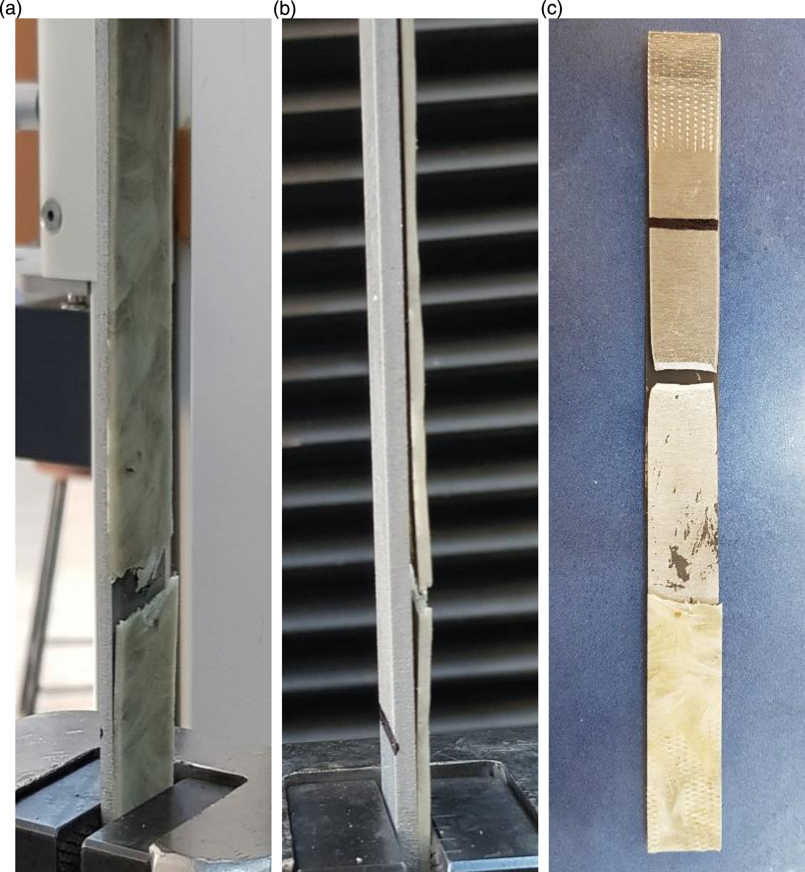
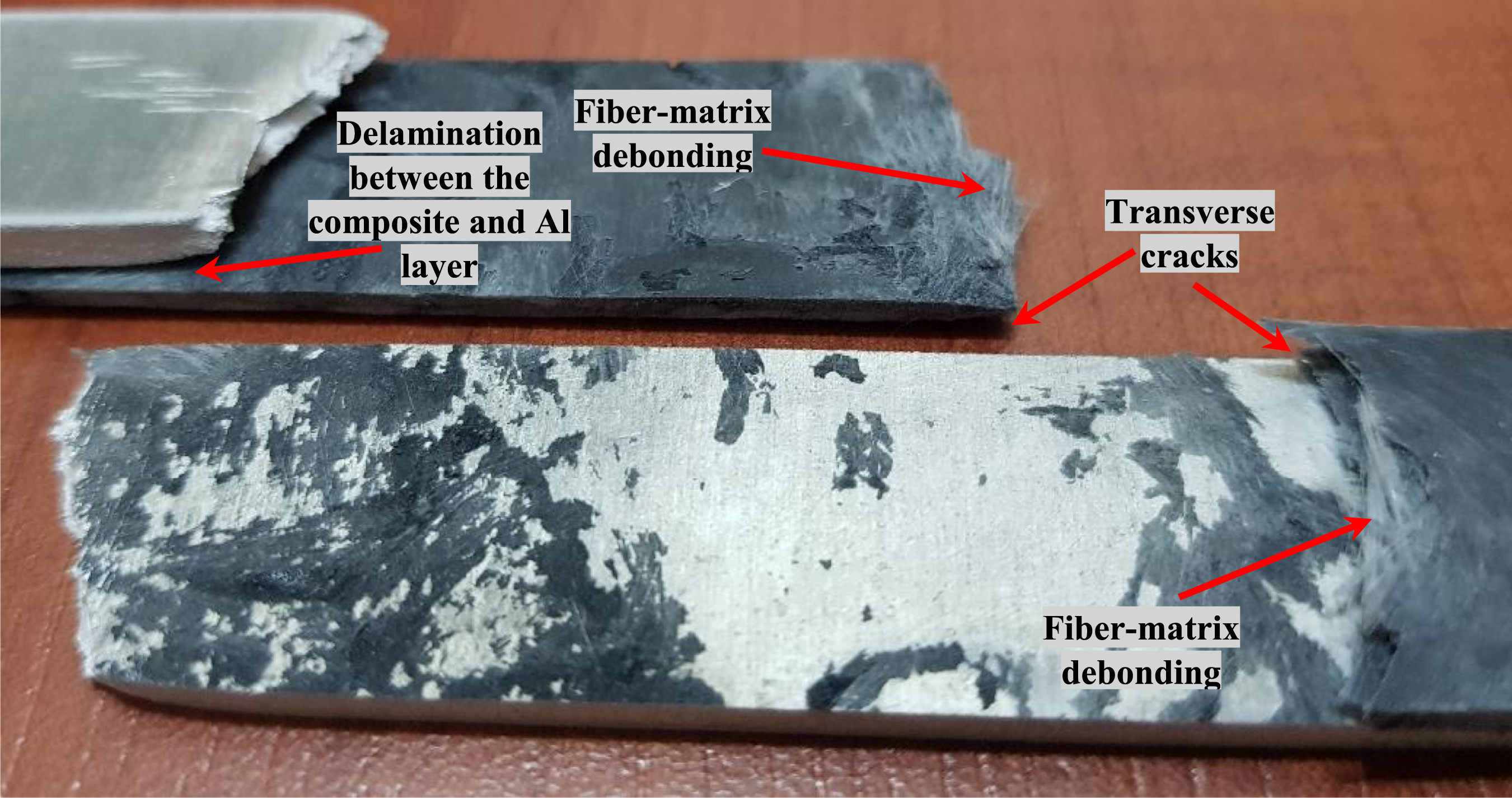
From the representative curve for the GF50-PP HLs (Figure 5), it can be inferred that no significant load drop was observed after failure of the composite layer contrary to the catastrophic failure of GF40-PP composites in the HLs. This may mainly be attributed to the gradually forming of debonding between fiber-matrix interfaces within the composite layer. A rapid tensile load increment up to the damage of composite layer with the elastic deformation of the metal layer is reported. Figure 9 also demonstrates the failure locations of a composite layer that was completely failed during the test and the AA7075-O after the tensile test. The associated multiple failure modes in these specimens are generally delamination failure between the composite and Al layers, fiber-matrix debonding and transverse matrix cracks in the multiple areas at various locations for the thermoplastic composite (Figure 10). The average of the fracture loads and equivalent strain values of GF50PP composite layers was noted as 8391.79 N and 1.3%, respectively. A modest load increase has been noticed when taking into consideration the tensile strength properties of the thermoplastic composites (Duramax LFT40-PP and Duramax LFT50-PP). Similar to the tensile behavior of the GF40-PP hybrid specimens, the AA7075-O layer continues to deform plastically and represents a similar behavior in terms of the strength to that of the AA7075-O base metal subsequent to the completely failure of the composite layer. Similar trend in percentage elongation at rupture (decrease by 32.44%) is also reported for these samples. As it is evident from the tensile test results, a significant influence of the composite fiber content in the hybrid structures on the tensile properties has not been reported. Fracture positions of a specimen of HLs with GF50-PP: (a) lateral failure of the composite layer during the tensile test, (b) AA7075-O layer after the test. Failure signs of the HLs with GF50-PP after tensile tests.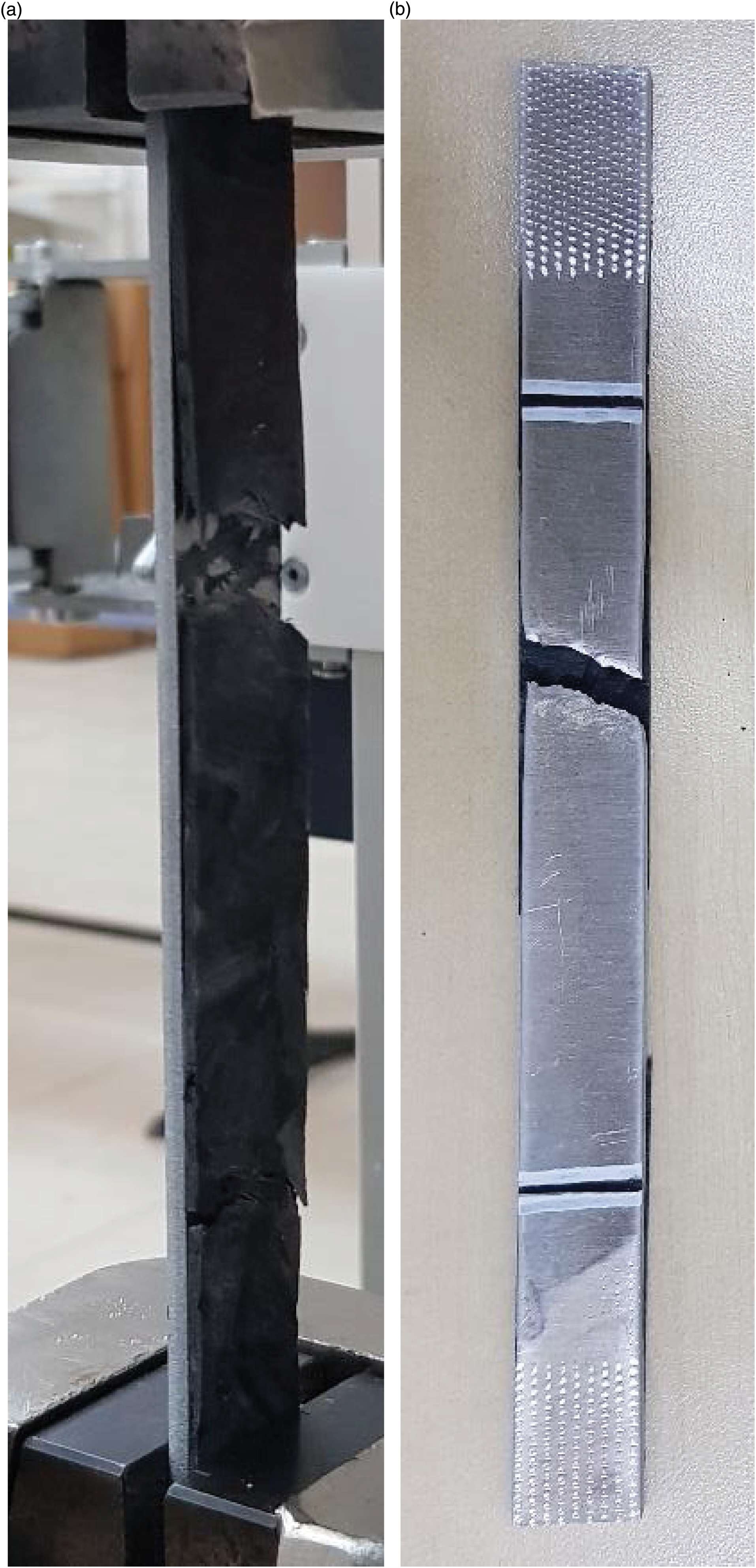
Flexural responses
Due to the asymmetrical structure of the hybrid composites, the three-point bending tests were carried out by applying the bending load on both surfaces of the HLs separately. In other words, the samples have been tested under flexural loading by two ways. Thus, it is aimed to investigate the effects of bending load applied from different surfaces on flexural responses. The flexural results for the HLs with the composite fiber amounts of 40 wt. % and 50 wt. % are plotted in Figures 11 and 12, respectively. (CL) and (ML) terms were used for the tests applied from the composite layer and the metal layer, respectively. As can be seen in Figure 11(a), the HLs subjected to a bending on the composite layer behave linearly with a rapid load increment up to a certain load (∼220 N) followed by a nonlinear response with a slower load increment up to a maximum load that initiates a failure with macro-cracks in the thermoplastic composite layer. The load then declines slowly with increasing deflection, predominantly. To summarize this typical response, deformation of the composite layer and AA7075-O layer are both elastic initially. As expected, no damage is detected in the layers within that period. After that, the slope of the curves decreases with respect to the initial straight-line portion of the load-deflection responses due to the inception of yielding in the Al alloy and micro-cracks in the composite layer.
79
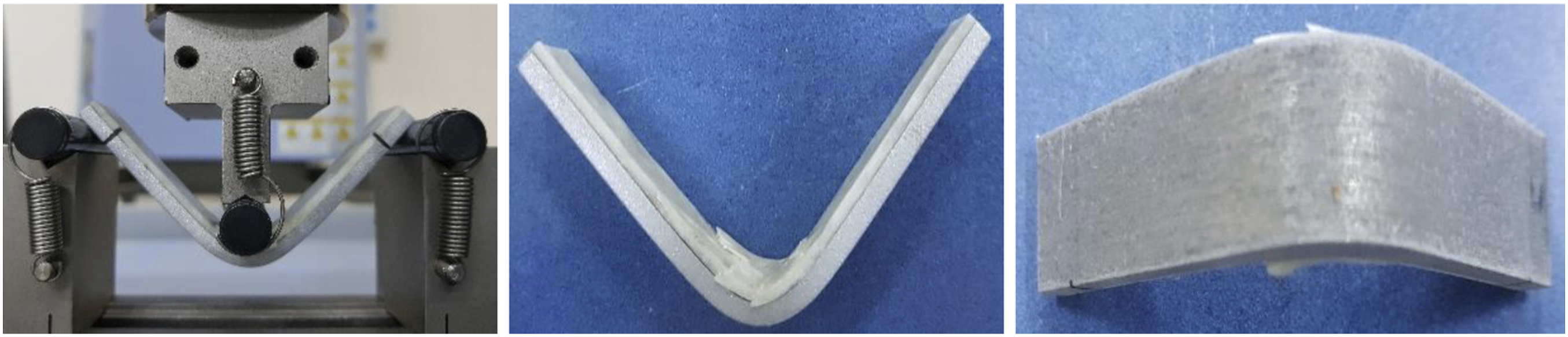
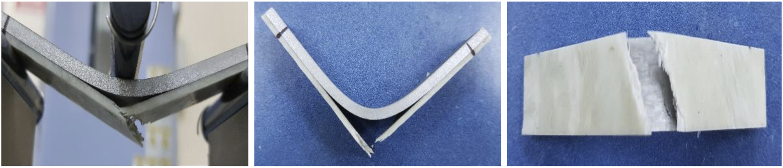
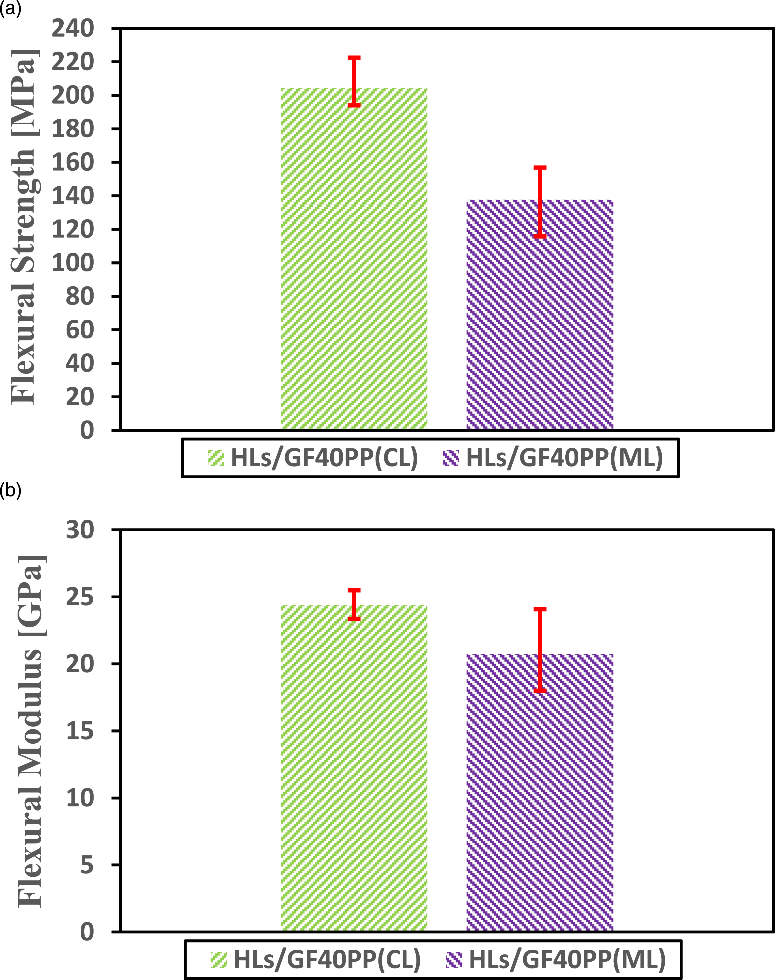
After reaching a maximum load that the composite layer can carry, local fracture around the load application point initiates. Lastly, complete failure of the thermoplastic composite layer with matrix cracking and the interface delamination causes the composite to be unable to bear load against bending. On the other hand, the sudden load drop was observed in only one sample. The detailed photo in the figure shows the interface delamination between the composite and metal layers during the testing. It was additionally discovered that there is no visible damage to the AA7075-O layer during and after the three-point bending tests. Furthermore, the specimens take a U-like shape during the method, as it is evident from Figure 13. From Figure 11(b), it can be found that a significant decrease of the maximum load was observed in all GF40-PP hybrid samples with the application of the load on the metal surface. Firstly, the HLs behave linearly in an elastic region. After the damage to the outermost composite layer (tension region) at a maximum load, it behaves close to ductile behavior. In that phase, there is a subsequent recovery after the sudden force drops for all samples. A lower maximum load is reported for a sample than the others. The detailed photo in the figure shows the catastrophic failure of the thermoplastic composite and the delamination between the composite and metal interface within the mid span. The specimens take a V-shape during the method, as can be clearly seen from Figure 14. However, the bending angle decreases subsequent to 30 mm deflection. This means that a lower flexural resistance is obtained as a result of bending on the metal surface. Deflection values corresponding to maximum loads are also lower compared to other samples (Figure 11(a)). Slope of the flexural response decreases by applying bending load on the Al alloy surface. This observation clearly demonstrates that the flexural modulus decreases with the AA7075-O layer in the compression region. Figure 15 exhibits the flexural properties of the HLs with GF40-PP thermoplastic composite in terms of the flexural strength and modulus. Flexural load-deflection curves of HLs with GF40-PP thermoplastic composite in case of: (a) the bending load is applied on the composite surface, (b) the bending load is applied on the AA7075-O layer. Flexural load-deflection curves of HLs with GF50-PP thermoplastic composite in case of: (a) the bending load is applied on the composite surface, (b) the bending load is applied on the AA7075-O layer. Photographs of HLs/GF40PP(CL) specimens. Photographs of HLs/GF40PP(ML) specimens. Comparison of flexural properties of HLs with GF40-PP thermoplastic composite:(a) Flexural strength, (b) Flexural modulus.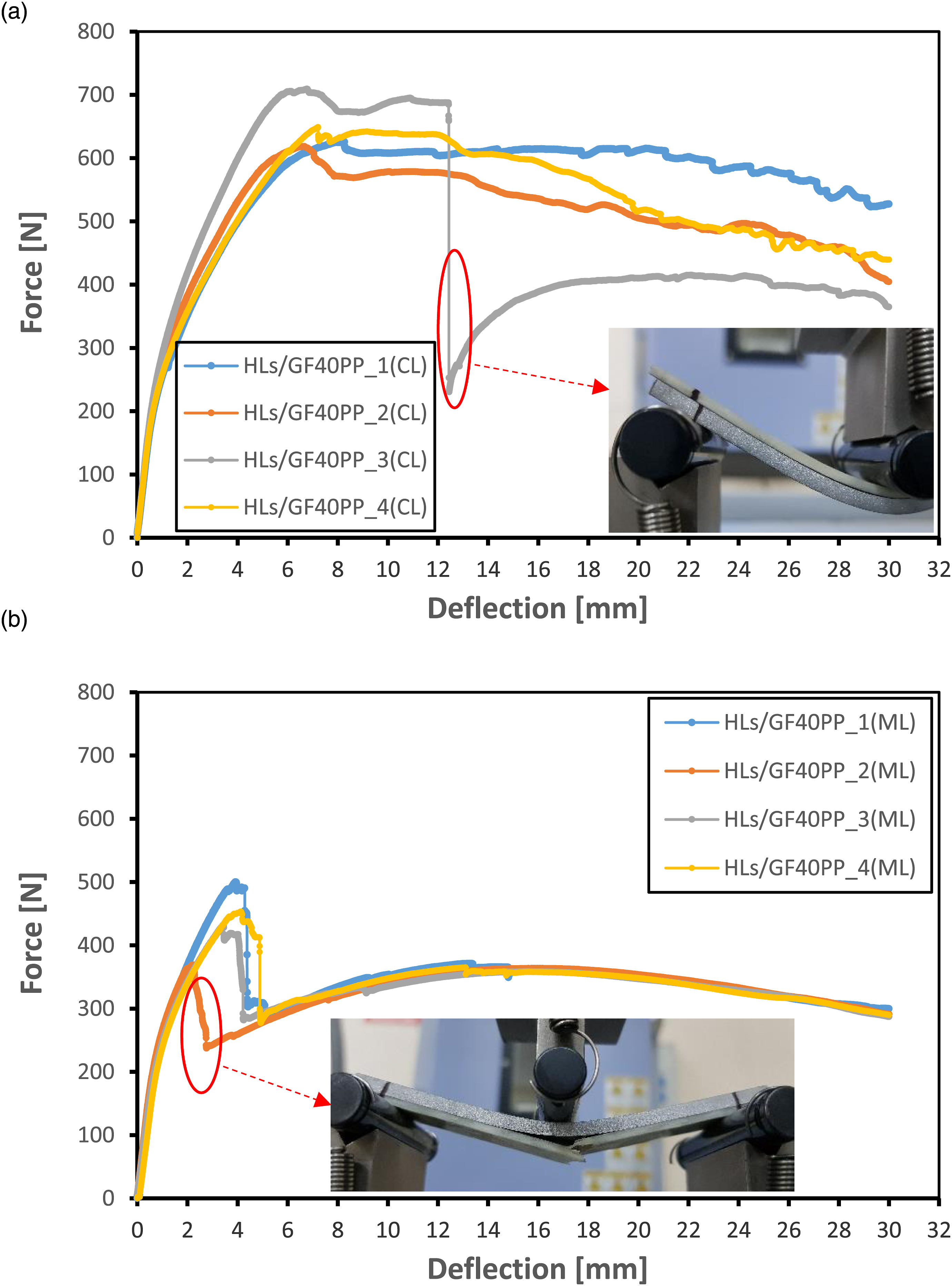

As it is noticeable from Figure 12, the bending resistance of the GF50-PP HLs is lower than that of GF40-PP hybrid samples for similar loading conditions whether the specimens are exposed to bending on the composite surface or on the Al alloy. This may be highly related to an inadequate load transfer process from one fiber to others by way of PP matrix after a certain fiber amount.
80
The augmentation of cross-linking density is also an important consideration for the flexural strength of composites.
81
The other reason may be due to increasing probable voids with the increased fiber content during manufacturing of both the thermoplastic composite panels and the HLs. In other respects, in case the GF50-PP hybrid specimens were loaded from the composite surface, the bending load they could bear were better than the GF40-PP hybrid samples being loaded on the AA7075-O surface. From the curves in Figure 12(a), it can be noted that the nonlinear response after the elastic region generally results in less deflection contrary to the GF40-PP hybrid samples. As the specimen bends, the composite sheet crushes and matrix cracks are seen at first peak. Figure 16 shows the forms of the specimens during and after the method. It has been observed that this region (nonlinear behavior) lasts much shorter in samples loaded on the metal surface. The bending load values obtained during the recovery phase after first peak are also close to the initial maximum load (Figure 12(b)). The specimens take an L-shape during the method, as can be clearly seen from Figure 17. This can be attributed to the fact that the Al alloy layer carries the bending load after premature failure of the composite and thus the bending response is represented by the Al layer rather than the hybrid structure. Based on these observations, it can be concluded that the GF50PP HLs subject to bending on metal surfaces have lowest bending strength in all samples. Flexural strength and modulus data calculated for the GF50PP HLs also support the findings as it is noticeable from Figure 18. When the load was applied on the Al alloy instead of the composite layer, the flexural modulus decreased as the highest modulus was in GF40PP laminates in case of loading on the composite surface. Photographs of HLs/GF50PP(CL) specimens. Photographs of HLs/GF50PP(ML) specimens. Comparison of flexural properties of HLs with GF50-PP thermoplastic composite:(a) Flexural strength, (b) Flexural modulus.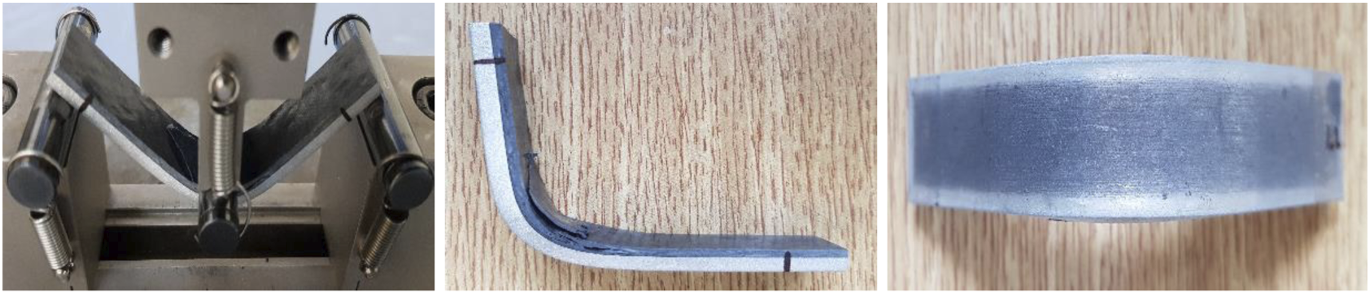
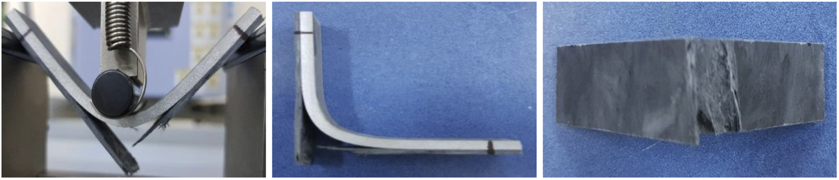
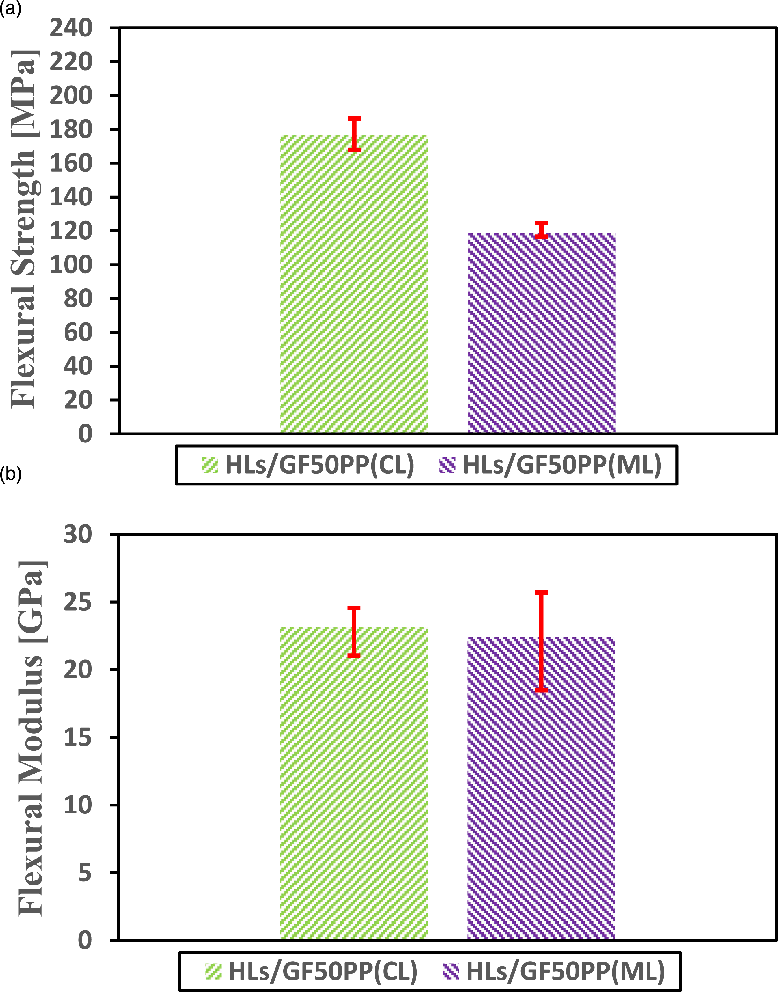
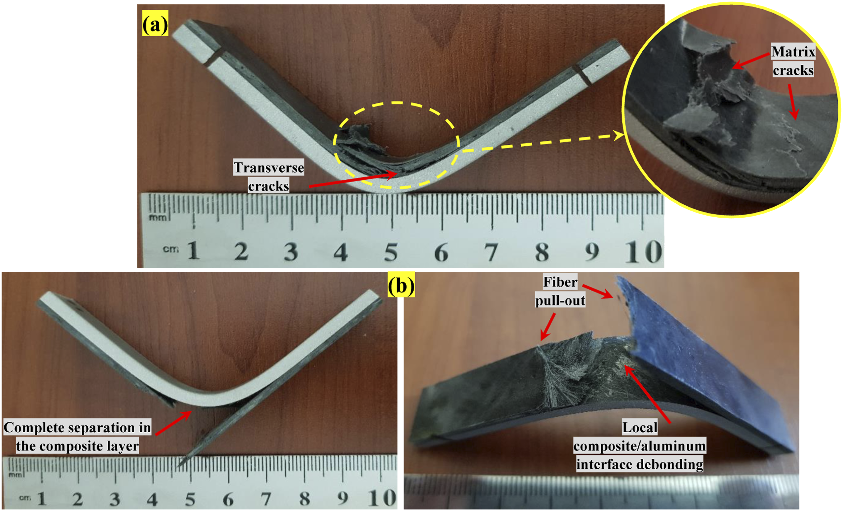
Figure 19 demonstrates the side views of the laminates with GF40-PP after the bending test method to assess failure mechanisms. Based upon the observations, HLs/GF40PP(CL) specimens show a compressive failure with matrix fretting. Matrix cracking and a slight composite/Al interface debonding at the midlength also draw the attention in these samples (Figure 19(a)). The formed cracks around the load application point in the composite layer propagated across the sample width towards the edges. It has been realized that other regions of the samples show good adhesion indicating an outstanding bonding level at the AA7075-0/GF40PP interface. Besides, no observable damage was reported at the bottom part (7075 Al alloy) of the HLs. In opposition to the aforementioned samples, HLs/GF40PP(ML) specimens exhibit a complete separation into two parts across the specimen width in the composite layer for all HLs (Figure 19(b)). No visible damage was observed on the top part (7075 Al alloy) of the HLs. Flexural failure signs of the GF50-PP HLs are also shown in Figure 20. From the figure, it can be inferred that the main failure mode of the laminates under flexural loading is due to the failure of the thermoplastic composite. HLs/GF50PP(CL) specimens show a compressive failure similar to the HLs/GF40PP(CL) specimens. The main failure sign is transverse cracks in the composite layer (Figure 20(a)). No obvious delamination was detected at the interface between the composite and metal layer. In addition, there is no damage to the lower surface of the laminate exposed to tension and other regions of the composite layer except the midlength. As observed in Figure 20(b), the main fracture signs consist of the failure of the composite layer at the tension side with fiber pull-out, and composite/Al interface debonding. As a matter of fact, the flexural properties were adversely affected by the increased fiber amount of the composite layer and severe failure signs at the tension side can be noticed for both HLs/GF40PP(ML) and HLs/GF50PP(ML) specimens. Photos of GF40PP hybrid laminates with failure signs after three-point bending test: (a) the bending load is applied on the composite surface, (b) the bending load is applied on the AA7075-O layer. Photos of GF50PP hybrid laminates with failure signs after three-point bending test: (a) the bending load is applied on the composite surface, (b) the bending load is applied on the AA7075-O layer.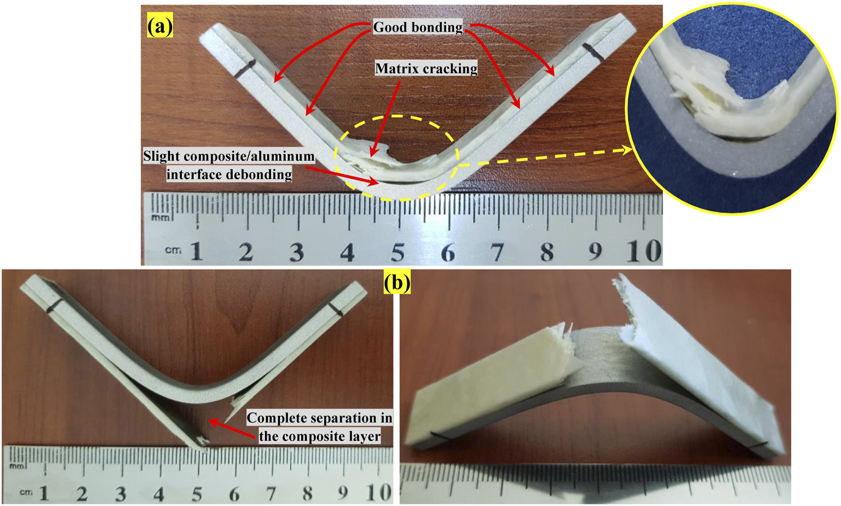
Fractographic characteristics
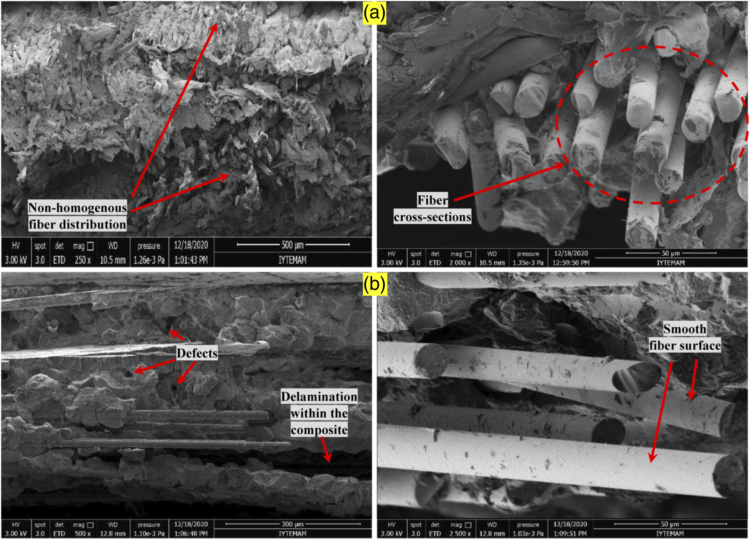
The SEM is utilized for elaborating the damage mechanisms of fracture surface of the HLs that are exposed to the uniaxial tensile and flexural loading. Fracture surfaces of the specimens with the PP fiber contents of 40 wt. % and 50 wt. % after the tensile tests are illustrated in Figure 21. The fractographs clearly demonstrate the pulled-out fibers as well as fiber/matrix debonding. Besides, cohesive PP matrix on the glass fibers is more notable in the fracture surfaces. These observations are in good agreement with the tensile properties of the HLs. The similarity in failure mechanisms and approximation between mean fracture load values indicate that there is no significant difference in the interlaminar fracture toughness for both HLs. Fractographic images for the failed GF40-PP HLs during the three-point bending tests are shown in Figure 22. Analysis of the Figure 22(a) reveals that the HLs/GF40PP(CL) specimens exhibit matrix cracking and some debonding. Simultaneously, a large number of pulled-out fibers are observed. The failure mode is mainly longitudinal delamination and debonding for the HLs/GF40PP(ML) samples (Figure 22(b)). In Figure 23(a), it can be seen that the HLs/GF50PP(CL) present non-homogenous fiber distribution with locally fiber agglomeration and many fiber cross sections indicating that fiber breaking or peeling from the matrix.
82
One can observe some voids in small quantities and fiber pull-out with insufficient fiber/matrix adhesion within the HLs/GF50PP(ML) specimens (Figure 23(b)). Scanning electron microscopy images of tensile fracture surfaces of HLs with:(a) GF40PP (b) GF50PP. Scanning electron microscopy images of flexural fracture surfaces of GF40PP hybrid laminates: (a) the bending load is applied on the composite surface, (b) the bending load is applied on the AA7075-O layer. Scanning electron microscopy images of flexural fracture surfaces of GF50PP hybrid laminates: (a) the bending load is applied on the composite surface, (b) the bending load is applied on the AA7075-O layer.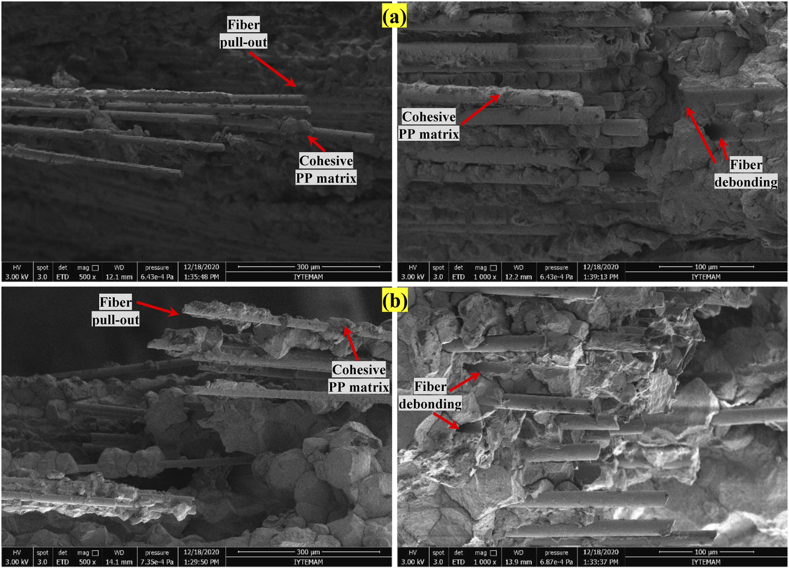

Summary and conclusions
In this study, the hot pressing technique for cost effective manufacturing of the GF-PP/AA7075-O hybrid structures is performed. Effects of the fiber amounts (40 wt. % and 50 wt. %) of the thermoplastic composite in the HLs on the mechanical properties in terms of the tensile and flexural responses are discussed on the basis of the experimental results. Fractographic analysis of the laminates based on GF40-PP/Al and GF50-PP/Al is also demonstrated through the SEM observations. The following conclusions can be drawn from the present investigation. (1) The applied surface pre-treatments (mechanical and chemical processes) of the 7075-O Al alloy for the production of HLs represent an acceptable level of bonding between the Al alloy and the composite layers considering the results of the mechanical characterization. (2) The uniaxial tensile tests show a small increase in failure strength of the composite layer for the HLs manufactured with 50 wt. % PP composite. (3) During the tensile tests, a significant decrease in the failure strain is reported for both HLs by comparison with the base 7075 Al alloy. (4) The macro and micro observations after the tensile tests reveal that the GF40-PP hybrid specimens show lateral failure with pulled-out fibers and interface debonding at a single location, whereas the GF50-PP hybrid specimens mainly exhibit fractures in the multiple areas at various locations with similar failure signs. (5) The three-point bending tests exhibit that the flexural strength and modulus decline for both HLs when the composite layer is at the tension side. (6) The GF40-PP hybrid laminates demonstrate the best interfacial bonding and flexural response in case of the bending load is applied on the thermoplastic composite surface. (7) The macro and micro observations after the flexural tests indicate that both GF40-PP and GF50-PP hybrid specimens show complete separation with fiber/matrix debonding in the thermoplastic composite layer when the Al layer at the compression side.
As a result, this work has shown that the hot-pressing is a promising cost-effective method for the manufacturing of HLs with thermoplastic composites and should be considered in future studies at various process parameters and with different types of composites. Further investigations are also suggested to evaluate the HLs with several sandwich configurations under different type of loading and environmental conditions.
Footnotes
Declaration of conflicting interests
The author(s) declared no potential conflicts of interest with respect to the research, authorship, and/or publication of this article.
Funding
The author(s) received no financial support for the research, authorship, and/or publication of this article.
Data availability statement
The raw/processed data used herein to justify these findings can be shared upon reasonable request. Interested researchers can directly contact the corresponding author.