
Abstract
Part I of this study established the concept and built the theoretical basis for a novel composite yarn. Part II deals with practical aspects of producing the yarn structural parameters necessary for flexible textile composite uses. This study investigates how to maximise the number of breaks of the core or foundation component of the yarn by using the design of experiment method. The results have shown that the number of these breaks vary between 1.4 and 6 times in comparison with only one break that would result from a typical conventional ply yarn. The analysis of the results indicates that a low overfeed ratio of 121% of the undulating component can lead to ∼4.7 breaks of the foundation component in comparison with only ∼2.6 breaks that would result using an overfeed ratio of 158%. To increase the number of breaks of the foundation component, it is necessary to use a high number of wraps, a low overfeed ratio, more than one input yarn for the foundation component and an undulating component of high tensile strength, which enhances its synergy with the foundation component by self-locking during breaking. Increasing the number of breaks of the yarn enhances the performance and safety of flexible composites.
Introduction
The yarn structure proposed as a novel reinforcement for making flexible FRPM composites is made of several components. These components are yarns of their own right, as shown in Part I of this study. Several researchers tried to understand the behaviour of this yarn by studying its yarn structure for decorative purposes. A few of other studies were carried out to understand the effect of false twist on the yarn structure and its tensile properties, 1 the effect of tension on the core or foundation component on the final structure 2 and the effect of the bending stiffness of the undulating or effect component. 3 The use of low tension on the foundation component may result in good quality bouclé undulations, which are being used in the traditional industry, whilst a low bending stiffness undulating component yarn helps to create a high number of regular small undulations while a high bending stiffness leads to a low number of irregular and larger undulations, producing undesirable appearance. It was also found that false twist should always be used to regulate the formation, appearance and number of undulations of the final structure.
A few other studies were concerned with the effect of the component yarns’ interactions on the whole structure. A study conducted to understand the interaction of bending stiffness of both the foundation and undulating components on the final yarn structure 4 confirmed the results of the previous study 3 and showed that a stiffer foundation component can produce larger undulations. In another study that tried to map the interaction of the overfeed ratio and the number of wraps, 5 it was shown that the ratio between the number of wraps and the overfeed ratio should be set to a specific value in order to control the formation of the resultant undulations. The value should be between 1.9 and 2.5 wpm to make gimp yarns and between 0.88 and 1.2 wpm to make bouclé yarns, and it was called ‘Structural Ratio of Multi-thread Fancy Yarn’. The manufacturing process and its interaction with yarn parameters was investigated in a few studies.6–11 They considered the three parameters of the hollow-spindle system: the supply speed of the undulating, the rotational speed of the hollow-spindle and the delivery speed of the final yarns, and by using response surface methodology experimental designs, they devised regression models that can predict the specifications of the undulations such as the number, height or width of these undulating profiles. The predicted undulations were not always regular or uniform and were limited to one particular type.
Another two studies showed that changing the overfeed ratio, the hollow-spindle rotational speed, the tex and bending stiffness of the undulating component can lead to changes to the intermediate product within the spinning zone.12,13 In particular, the higher the overfeed ratio, the wider the diameter of the undulating component helices, while the higher the speed of the hollow spindle, the higher the number of the undulating-thread helices, but with a reduction in their diameter. These changes affected the appearance of fancy yarns; in that, the high number of helices resulted in more undulations, while wider helices resulted in bulkier undulations. It has been considered that an undulating yarn with high stiffness may be needed to make the yarn structure more uniform. However, at a low number of wraps of the wrapping component, the thickness of the undulating yarn may be more important than its stiffness. It should also be pointed out that if the thickness and stiffness of the undulating yarn and the rotational speed of the machine were all controlled properly, it is possible to change the resultant undulations to produce bouclé profiles, gimp profiles, wavy profiles or loop profiles even when using the same number of wraps and overfeed ratio. 13
A different approach was adopted in two other similar studies on the structure of a yarn that was made by combining a hollow-spindle and a ring-spindle system in one operation.14,15 It was found that the overfeed ratio of the undulating component and the number and direction of wraps of the wrapping component affect the height and number of the undulating bouclé profiles. The tensile properties of a bouclé yarn, a wrap yarn and a spiral yarn made on the ring spinning system, using three-component and two-component yarns were the subject of another study. 16 It was shown that there were two breaks for the three-component wrap yarn and bouclé yarn, and only one break 16 for the three-component spiral yarn. All yarns made with only two-components had only one break. It is inferred from these results that although limited to only two breaks, the use of three input components is essential for obtaining more than one break and for increasing the performance of the final yarn. 16
Studies involving seven factors were also conducted to understand this novel yarn structure. The linear density of the final yarn, 17 its aesthetics and structural properties, 18 its tensile strength and elongation at the first break 19 and the maximum tensile strength that it can endure after several breaks 20 have been studied in relation to spinning conditions. The seven factors studied were the delivery speed, the supply speed, the rotational speed, the false twist, the material type and form of the foundation, and the undulating and the wrapping components. The overfeed ratio and the number of wraps, resulting from the interactions of the three speeds of the hollow-spindle machine, were also studied. The outcomes using design of experiment of these studies have established the significant factors and interactions that affected the properties of the yarn, and regression models that can predict these properties.
Regardless of the type of input materials and method of manufacture, several studies were conducted to establish rules for the assessment of the uniqueness of the yarn structure21,22 and how to classify23–26 and model the yarn structure mathematically.25–27 Mathematical models of the geometry of similar composite yarns made for decorative applications were also devised for modelling the tensile strength of the yarn.25,28,29 In one particular study, to describe the structures of eight yarn variants, a mathematical model was introduced by considering the lengths of the undulating and foundation components and taking into account that the undulation component has both sinusoidal (wavy) segments and sigmoidal segments (or helical segments). 26 These yarn variants were simple wavy yarn, gimp yarn, gimp yarn derivatives, spiral yarn, overfed fancy yarn, bouclé yarn and semi-bouclé (or bouclé-like) yarn. 26 Other geometrical models30,31 focused on the length of the wrapping component, and its effect on yarn appearance.
All those studies in the literature have been conducted for understanding the aesthetic appearance and properties of traditional yarns called fancy or bouclé yarns, which can have three-component yarns, using the same spinning system, and have not considered the construction, characteristics, production and performance of these yarns for industrial end uses such as in flexible composites. In Part I, we have explored the concept and provided the theoretical background for the use of these yarns in flexible composites, and in this Part II, we try to show how the tensile performance of this yarn can be maximised by increasing the number of yarn breaks prior to total failure. Hence, a flexible polymeric composite reinforced by these novel yarns may sustain high strains without a complete failure by engineering successive breakages of the foundation component yarn which is sustained by its self-locking when subjected to tensile loading. This will be shown in the following sections.
Methodology
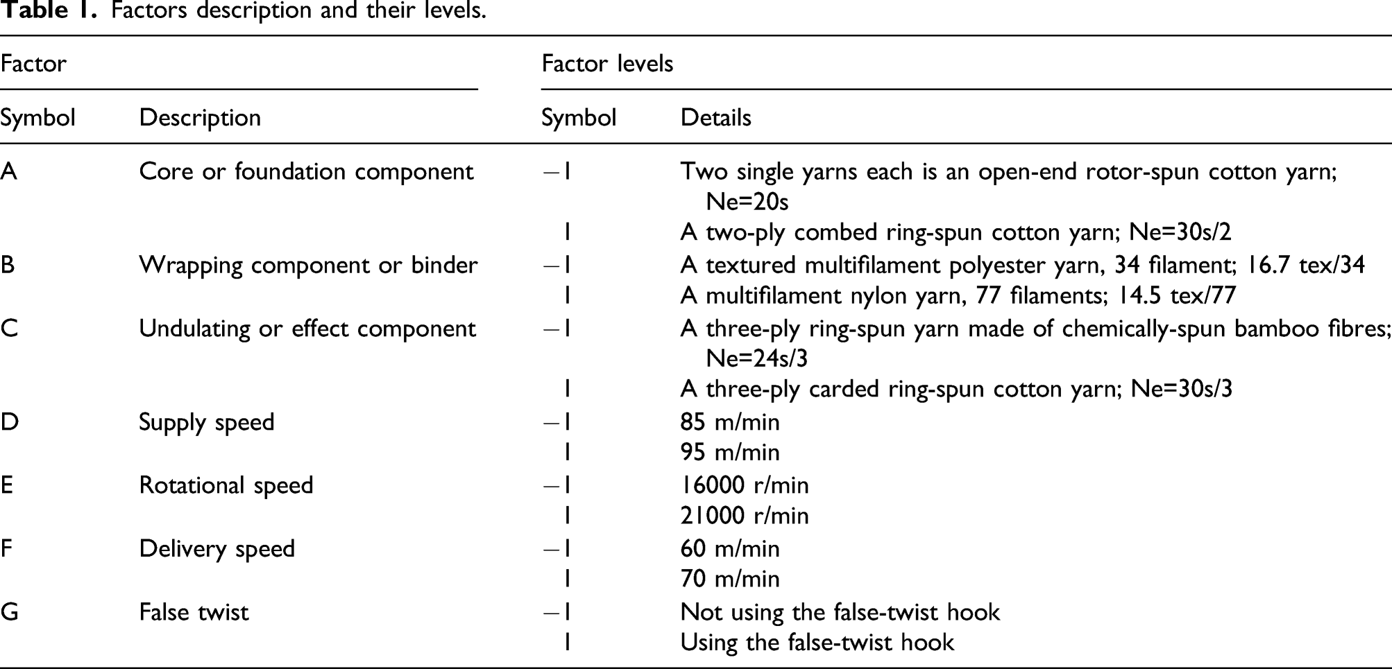
Factors description and their levels.
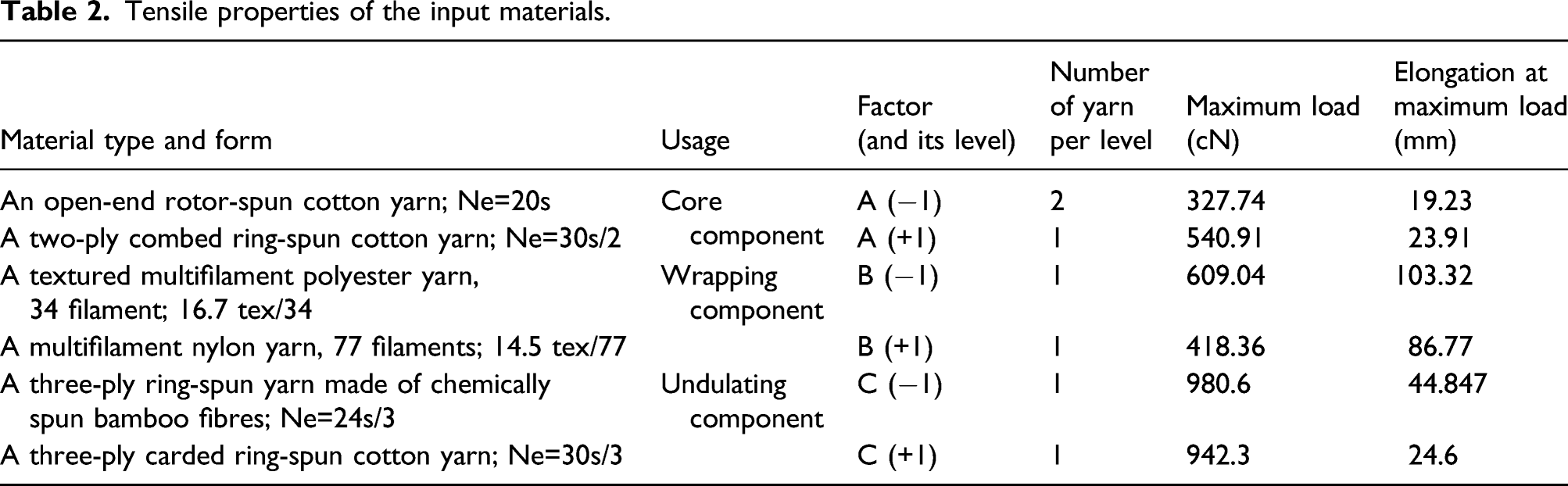
Tensile properties of the input materials.
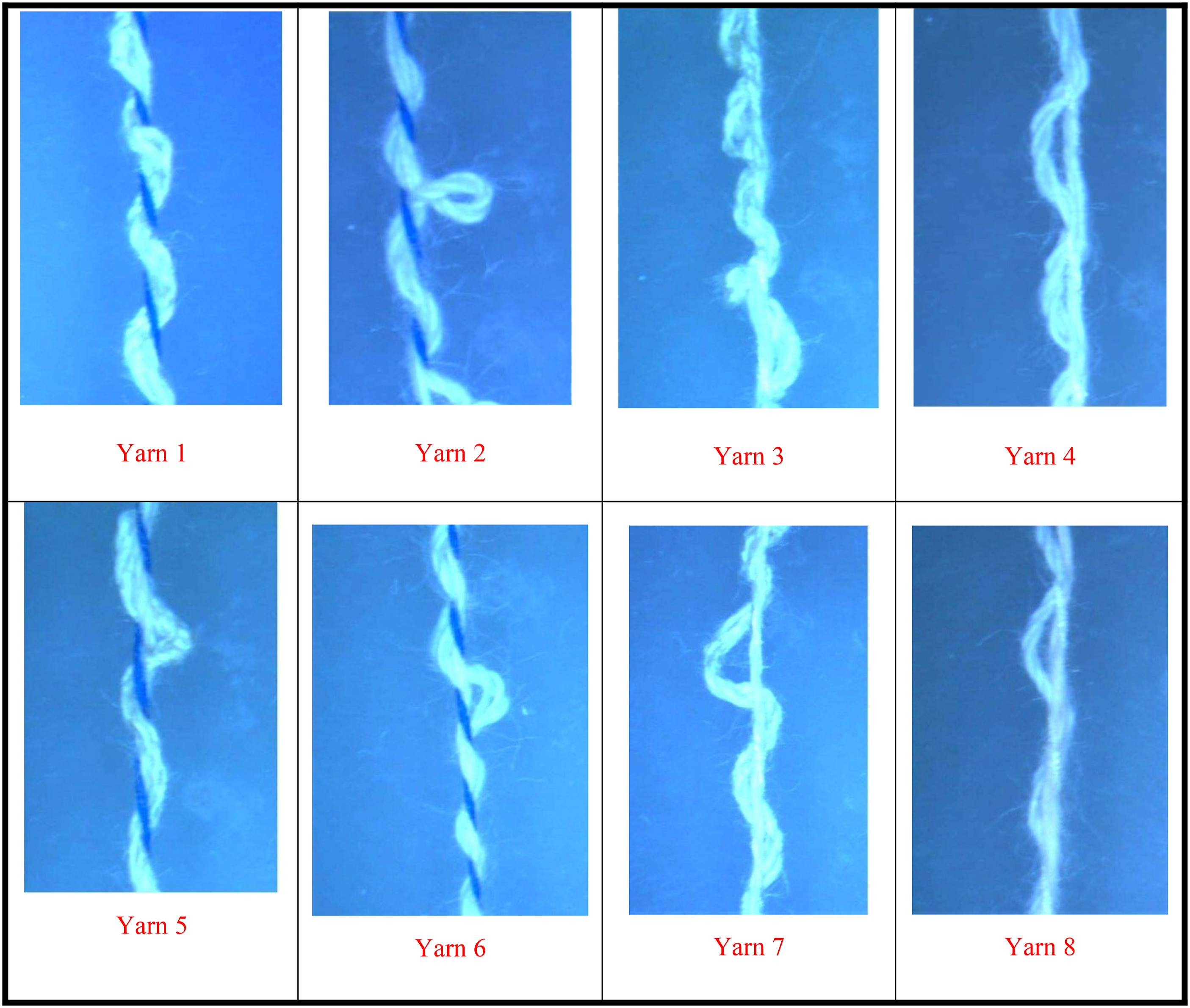
Images of the composite yarns made based on the standard order of trials.
Fractional factorial experimental design of this study.
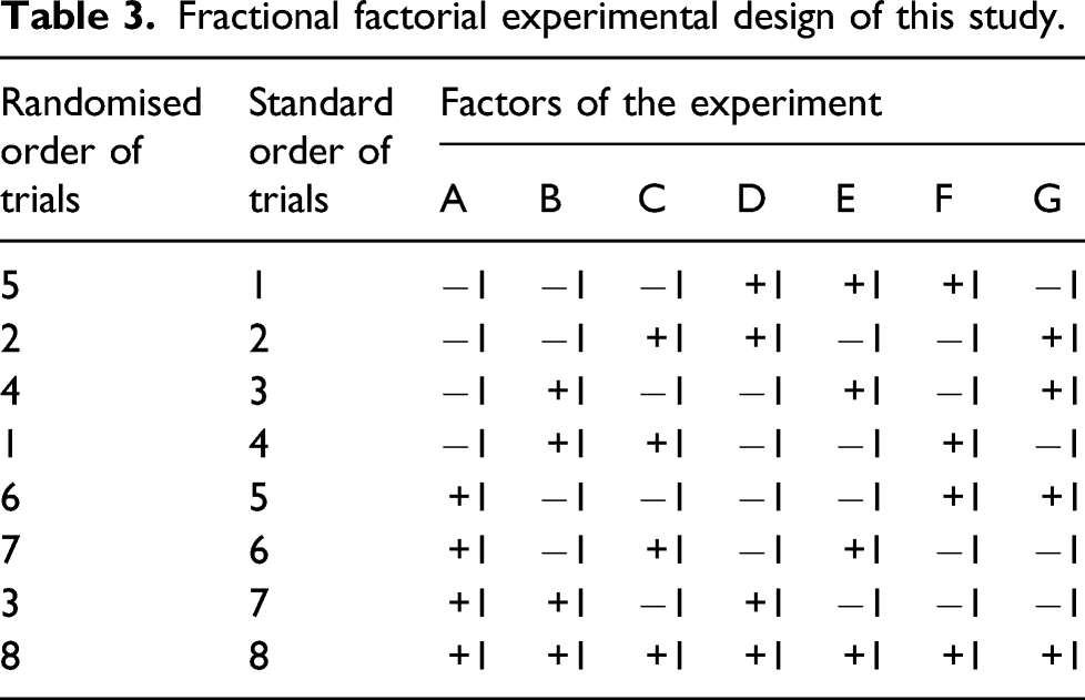
This experimental design was an orthogonal array
33
of an ‘alias structure’ producing confounding effects. The general alias structure for the main effects and two-level interactions are defined
33
as follows 
The eight trials of the experiment were conducted in a random manner, as shown in Table 3, to minimize relation bias. The experiment itself with its eight trials was repeated five times in the same random order used for the first replicate. For each experimental trial, a hybrid complex-structure reinforcing yarn was obtained; thus, eight different reinforcing yarns were obtained for each replicate. Each yarn was wound on a package, so the total number of packages for the five replicates was 8 (yarn trials) × 5 (packages) = 40 packages. The five yarn packages made for each trial represent one yarn structure. Similar to the input yarns, the resultant novel yarns were tested to measure their tensile properties as shown above. For each of the eight novel yarn structures, the total number of specimens was 20, where 4 specimens were taken from each of the 5 relevant yarn packages (4 × 5 = 20). The specimens were randomly selected before being tested. The mean and standard deviation values were then calculated.
Results and discussion
Initial results
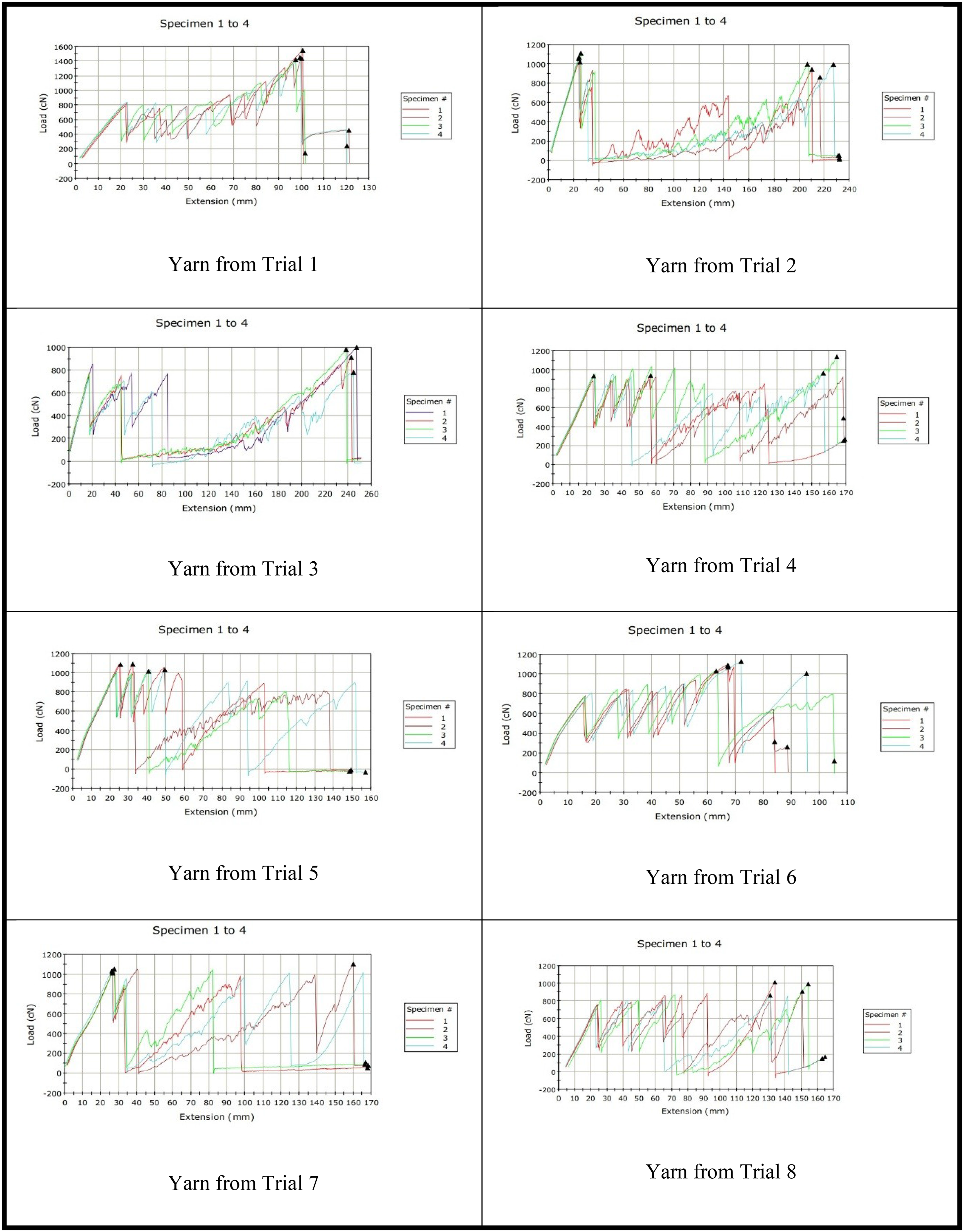
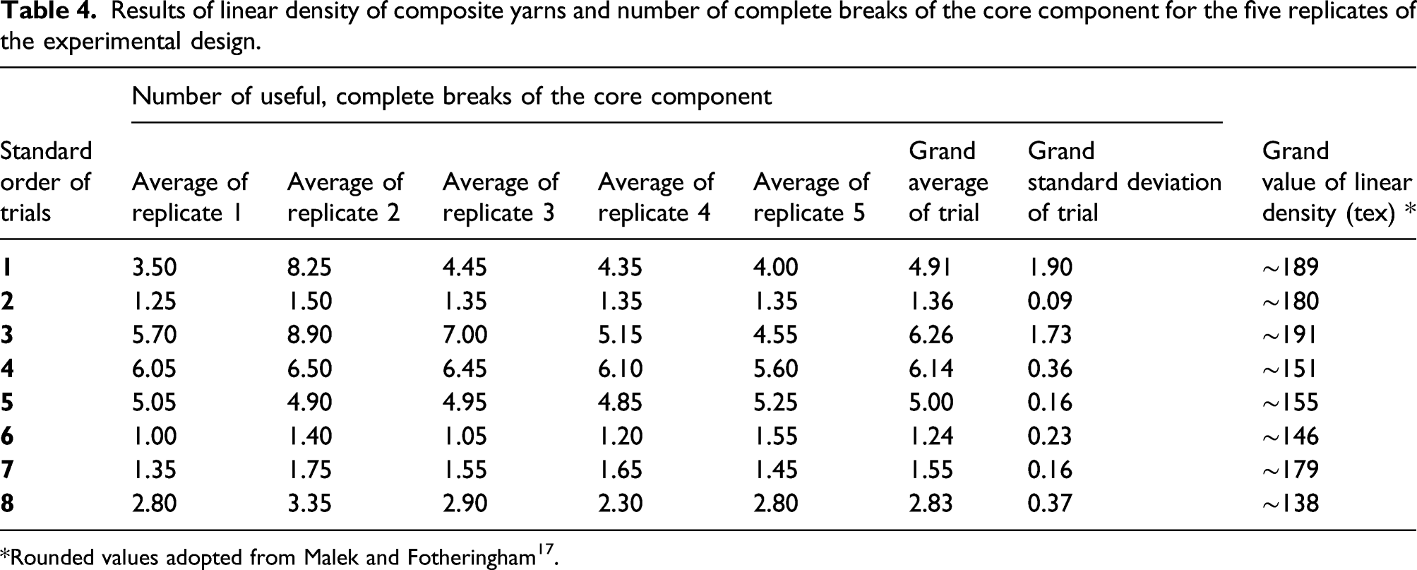
Images of the yarns made using the experimental design are shown in Figure 1 while examples of the load-elongation charts of the yarns are given in Figure 2. This figure shows the breaking patterns of four representative specimens sampled from one of the five packages of each of the eight yarns. It is shown that the yarn components have broken more than once. For instance, using the concept of complete breaks as defined in Part I of this study, eight complete breaks of the foundation component have resulted in the case of Trial 1. This is seen by the red and green tensile load-elongation plots in the figure. All plots of Figure 2 show that the number of breaks of the foundation component are different in each trial. These breaks are important and have practical influence on a FRPM composite performance, as already discussed in Part I, so the results of the five replicates are given in Table 4. Load-elongation charts for the composite yarns made as shown by the experimental design. All these yarns are made using different materials, technological parameters of the machine, number of wraps or overfeed ratio. Results of linear density of composite yarns and number of complete breaks of the core component for the five replicates of the experimental design. *Rounded values adopted from Malek and Fotheringham
17
.
Analysis and discussion of the initial results
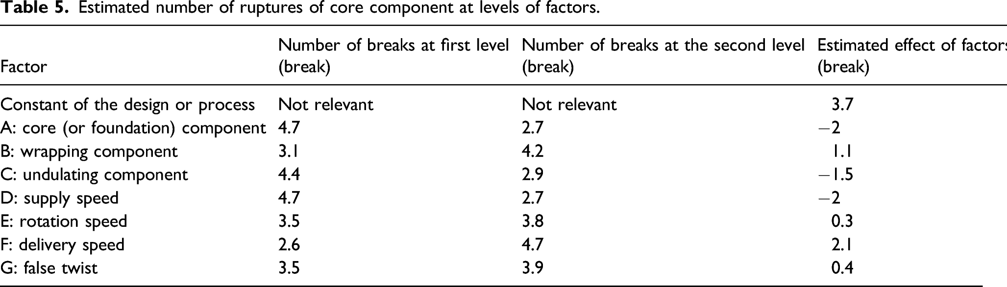
Estimated number of ruptures of core component at levels of factors.
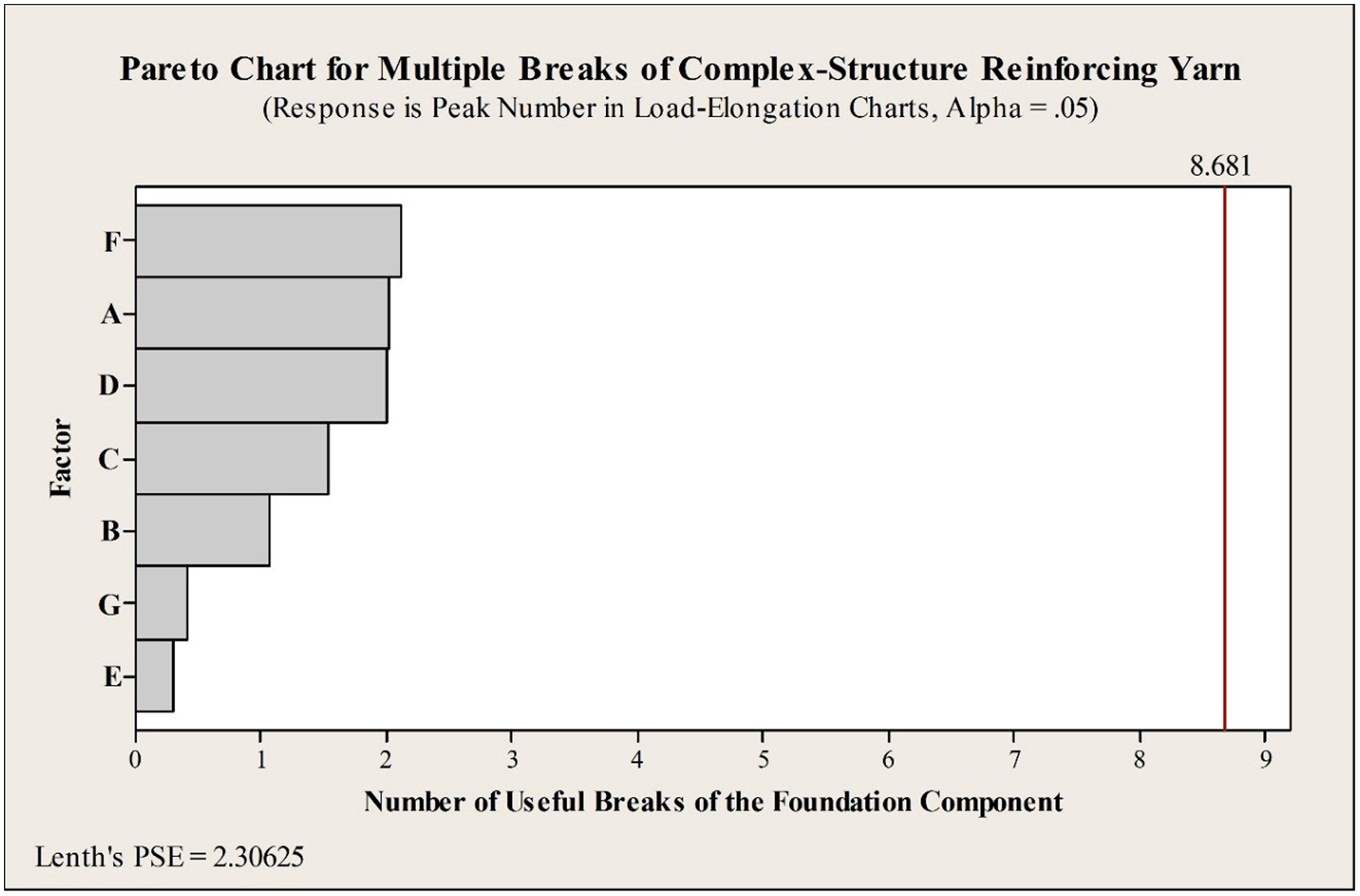
Pareto chart for the number of breaks of the core component: Symbol A is used for the core component, B for the wrapping component, C for the undulating component, D for the supply speed, E for the rotational speed, F for delivery speed, and G for false twist.
It is also shown that even though the Ne = 24s/3 three-ply bamboo yarn (used in Level −1) and the Ne = 30s/3 three-ply cotton yarn (used in Level +1) were approximately similar in tensile strength, see Table 3, the Ne = 24s/3 bamboo yarn allowed for a higher number of breaks for the foundation component. This is because the Ne = 24s/3 bamboo yarn was approximately two times more extensible at break than the Ne = 30s/3 cotton ply yarn (Table 3). Therefore, the higher extensibility allowed this component to get entangled with both the wrapping and foundation components producing higher successive number of breaks of the foundation component yarn than in the case of the less extensible Ne = 30s/3 cotton yarn. So the broken yarn segment of the foundation component is re-entangled and re-locked into the structure and hence carrying the tensile load again until the next break over several times in succession depending on the individual properties of the component yarns and the spinning process parameters. The more extensible the undulating component, the higher the number of the foundation component breaks.
Figure 2 indicates that the wrapping component (i.e. factor B) is also an important factor, and that the use of two different types of yarn leads to different results. The nylon non-textured multifilament wrapping component was weaker and less extensible than the textured polyester multifilament, shown in Table 3. The less extensible nylon multifilament can force the undulating component to become entangled with the broken foundation components more quickly. Therefore, it has the ability of locking the broken foundation component segments, which is reflected in obtaining the several peaks seen in the tensile load-elongation charts, as confirmed in Table 5 which shows that the first and second levels of the wrapping component – the polyester and nylon multifilament – were responsible for obtaining 3 and 4 breaks for the foundation component, respectively. At the same time as the three components become entangled, they all can take part in carrying the load. This explains the increase of the tensile load that is recorded after the first break of the foundation component. The frictional force of the wrapping component with the foundation and the undulating components may also influence the locking mechanism of the broken segments of the foundation component. Since the nylon component is not textured, a high number of its filaments have contact with the other two components, while only a few filaments of the textured polyester component contact the same surfaces of the component yarns. So greater friction of the wrapping component assists synergistically the breaking mechanism of the foundation component.
Figure 3 also indicate that the weakest factor was factor E which is the rotational speed of the hollow-spindle, with only 8.19% influence, and the second weakest factor was factor G (false twist) which had only a small contribution; so both of these factors can be ignored. With regard to false twist (Factor G), a previous investigation of the hollow-spindle system indicated that using the false-twist hook that is attached to the output hole of the hollow-spindle is useful in producing a highly wavy-shaped-structure yarns, such as gimp and semi-boucle yarns, made by the wrapping process. 1 Such a highly wavy-shaped yarn structure can promote the role of the undulating component in helping the wrapping component to lock the broken segments of the foundation component. A 0.5 increase of the number of foundation component breaks can be seen in Table 5.
The supply speed (or factor D) does not have a direct influence on the foundation component. This is because, by design, the supply rollers do not control the foundation component, and they do not push it forward in any hollow-spindle spinning or wrapping system. Instead the foundation component is pulled forward by the delivery rollers that control the final yarn structure.
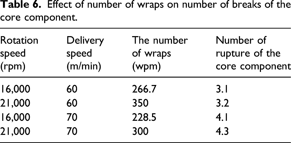
Effect of number of wraps on number of breaks of the core component.
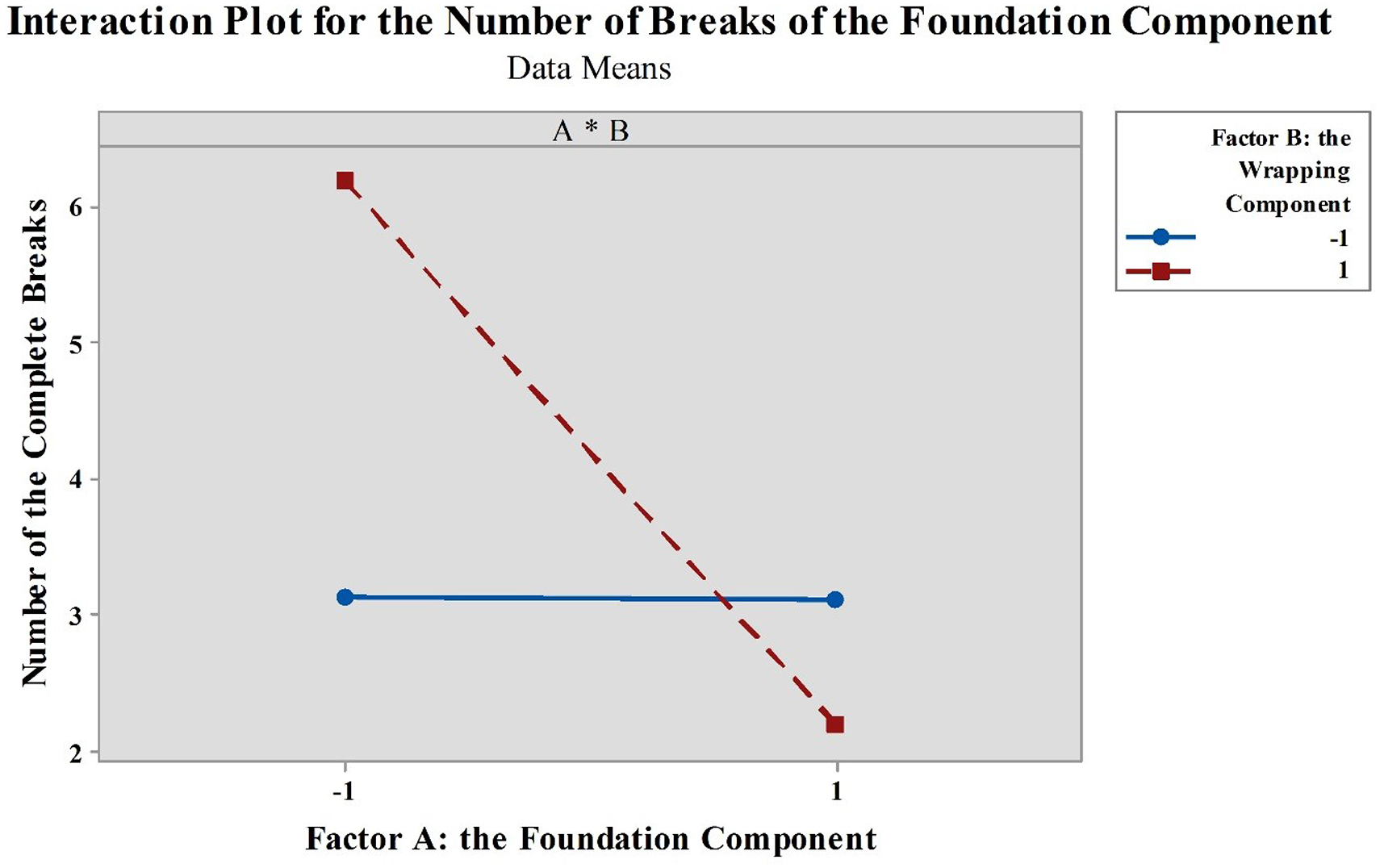
Interaction plot of the core component and the wrapping component and their collective effect on the number of breaks of the core component.
With regard to the delivery speed (factor F), it was inferred from Table 6 that raising the delivery speed from 60 to 70 m/min increased the number of the foundation component breaks from about 3 to 4. Therefore, potentially, the delivery speed could be another important factor to be considered. This is because the higher the delivery speed, the higher the foundation yarn tension, so the higher the entanglement of the yarns between each other. This also promotes greater frictional forces between the components.
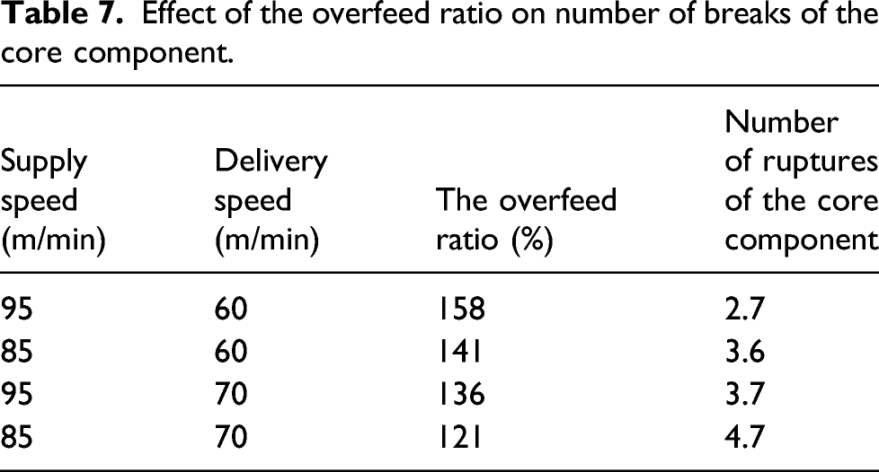
Effect of the overfeed ratio on number of breaks of the core component.
Statistical analysis for the number of breaks of the core component
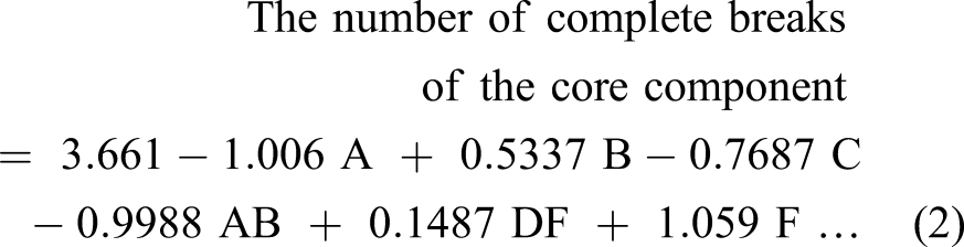
Minitab 15 was used to obtain a regression model to measure the number of practical breaks of the foundation component based on all factors established in the above investigation. Accordingly, the regression model of equation (1) was obtained. The p-values of the terms of this model were found to be all significant at a significance level α = 0.05, except for factor D which had a p-value = 0.095; thus, it was significant only at α = 0.10. Based on our analysis given in the section Analysis and Discussion of the Initial Results, it is inferred that factor D is not the important factor, instead the effect is claimed by the interaction AB. Therefore, by replacing factor D in equation (1) by the interaction AB, the regression model took its final form in equation (2). A method of calculating an interaction of factors is given elsewhere.33 Therefore, equation (2) should be used to estimate the number of complete breaks of the novel structure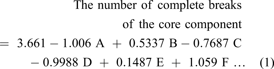
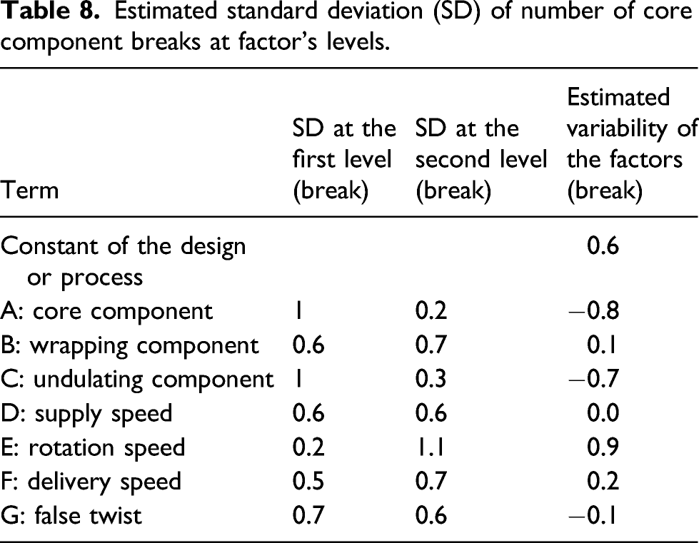
Variation in the number of breaks of the core component
Estimated standard deviation (SD) of number of core component breaks at factor’s levels.
Conclusions
Part II of this study was conducted to investigate the materials-process-structure relationships and to show how they affect the number of breaks of the foundation component. The study continued with how to maximise the number of breaks of the foundation component of the novel reinforcing yarn structure, as introduced in Part I. The results from the factorial design indicated that the number of the foundation component breaks is related to the material type and form of the foundation, wrapping and undulating components, the delivery speed, the use of false twist, the interaction between the foundation component and the wrapping component, and the overfeed ratio. Specifically, it was found that a higher number of the foundation component breaks resulted when using • a relatively low overfeed ratio of the undulating component, that is, 120%–130% instead of more than 150%; • a high value of the delivery speed, that is, 70 m/min; • two single yarns for the foundation component, even if they were weaker and less extensible than one stronger ply yarn; • an undulating yarn with high extensibility; • using a non-textured nylon multifilament wrapping component, even if it is weaker and less extensible than for instance a textured polyester multifilament; and • by maximising the interaction between the foundation component and the wrapping component due to friction using two single yarns for the core component and non-textured nylon multifilament for the wrapping component.
This study is presenting a novel flexible high-performance composite yarn assembly which is comprised of a minimum of three yarns. The configuration of this yarn is interesting because as it is shown, it can provide a locking mechanism to a foundation yarn by wrapping it and, hence, allows the structure to carry a load by successive structural breaking and locking. This mechanism is explored in this study for the first time for the purpose of high performance because all other studies focused primarily on the aesthetic appearance of fancy yarns that are made by the same process and fancy garments made of them. This investigation has shown how the geometry of this yarn and its process interaction can produce high-performance load-bearing yarns desirable for flexible FRPM and other industrial end uses.
Footnotes
Declaration of conflicting interests
The author(s) declared no potential conflicts of interest with respect to the research, authorship, and/or publication of this article.
Funding
The author(s) received no financial support for the research, authorship, and/or publication of this article.