
Abstract
Combining discontinuous carbon fibre moulding compounds with unidirectional (UD) non-crimp fabric has been studied as a potential solution for producing cost effective composite structures, with short cycle times via compression moulding. The tensile stiffness and strength of a composite with a hybrid fibre architecture were found to be up to 60% and 110% higher, respectively, than the baseline discontinuous fibre moulding compound, when 20% (by vol.) of UD fibres were aligned in the primary loading direction. However, stress concentrations arising from the dissimilar material properties can result in the strength of the hybrid architecture being reduced to below that of the baseline composite if the UD fibres are not incorporated effectively. This paper focusses on optimising the stress transfer within the transition zone (inter-material interface) between the UD material and the discontinuous fibre moulding compound, when local isolated patches of continuous fibre are used rather than full coverage plies. This is key if hybrid architectures are to be adopted for structural applications, minimising the stress concentration effects from the UD ply ends, whilst maintaining the low cycle times and costs associated with compression moulding. Following aerospace laminate design guidelines, a range of step sizes and joint configurations have been considered for different ply drop strategies, minimising the magnitude of the stress concentration at the UD ply ends. Results indicate that the step length must be at least 20 times the thickness of the UD ply to ensure the bending strength at the joint is the same as the baseline discontinuous fibre material. An ‘alternating joint' yields 18% higher bending strengths than a conventional ‘stepped joint’ design, as the stress concentrations at the dropped ply ends are reduced in comparison to the inherent stress concentrations within the discontinuous fibre material.
Introduction
Compression moulding offers the fastest route for manufacturing composite components from thermoset matrices, with sheet moulding compounds (SMCs) being the most widely used form of fibre reinforced composites for high volume applications. 1 The cycle time is typically just 5–10 min depending on part thickness, which is suitable for production volumes approaching 100,000 parts per annum. However, the ultimate tensile strength of these materials is typically limited to approximately 50% of a comparable continuous fibre quasi-isotropic laminate, 2 due to the large stress concentrations at the bundle ends.3,4
The majority of SMC materials are derived from chopped glass rovings and mineral filled polyester resins, which are typically used for cosmetic applications, including automotive body panels. A number of manufacturers have exploited the higher specific properties of carbon fibres to produce Advanced SMCs,5,6 which have been utilised for automotive chassis components, aerospace interiors and secondary structural components.7–9 Carbon fibre epoxy SMC variants tend to be derived from UD prepregs9,10 and are therefore expensive, whilst vinyl ester variants typically have lower failure strengths due to weaker interfacial adhesion between the matrix and the fibres. A recent paper by the authors 11 presented a method for producing low-cost epoxy-based carbon fibre moulding compounds using a robotic deposition process. Directed Fibre Compounding (DFC) simultaneously sprays low viscosity epoxy resin and discontinuous carbon fibre bundles to create a charge, using the constituent materials in their cheapest form. This process can be used to produce low-cost carbon fibre/epoxy compounds with similar mechanical properties (tensile strength of 323 MPa and Young’s modulus of 36.3 GPa 11 ) to a commercial prepreg-derived equivalent (tensile strength of 300 MPa and modulus of 38 GPa 9 ).
The addition of a localised patch of continuous unidirectional (UD) fibre plies to the discontinuous DFC material has the potential to improve the stiffness and strengths of compression moulding compounds 12 , making them more suitable for structural applications in both the automotive and aerospace sectors. This creates an opportunity for producing highly optimised fibre architectures, by aligning continuous UD fibres with principal stresses for the primary load case 13 and exploiting discontinuous fibres for secondary stress states such as off-axis loading, or for damage tolerance requirements. 14
Gortner et al. 15 combined dry textile preforms with SMC to produce a hybrid discontinuous/continuous fibre architecture, but mechanical performance was limited due to the poor impregnation of some area of the textile during moulding. Wulfsberg et al. 7 investigated the feasibility of using hybrid fibre architectures to produce aerospace structures, by co-compression moulding UD prepreg and carbon fibre-SMC (CF-SMC). Similarly, Akiyama 16 demonstrated that it is possible to achieve regions of high stiffness and strength by locally reinforcing a moulding compound with UD prepreg in relatively simple planar regions of a component. SMC material was used exclusively in complex regions of an automotive floor-pan to add features such as ribs or to embed fasteners, which would otherwise be difficult to achieve with fabrics.
The ply shapes for the continuous fibre reinforcement in a hybrid architecture should be as simple as possible to ensure high material utilisation when nesting plies and to aid automation. 17 It is also important to ensure that hybridising does not compromise the cycle time advantage of compression moulding over competing processes. It is impractical to cover large areas of a complex compression mould tool with continuous fibres because of the increase in charge preparation time.
Resin B-staging has been considered13,18 to control the migration and distortion of local UD patches when co-compression moulded with discontinuous SMC. The UD material is typically staged (partially cured) before moulding to decrease the degree of distortion induced by the flow of the discontinuous material. This can however compromise the inter-laminar shear strength (ILSS) between the UD plies and the SMC if the initial staging level is too high. Ply distortion was also found to be sensitive to the UD ply stacking sequence, 13 which can be optimised by ensuring the inextensible UD fibres are aligned in the principal SMC flow direction to reduce UD fibre waviness.
Designing structures using hybrid fibre architectures is complex due to material heterogeneity, but also potential perturbations caused by material flow during the compression moulding process. Current studies on hybrid architectures tend to focus on flow-induced fibre orientation effects caused during moulding,
19
or the consequential microstructural mechanical behaviour.
20
Whilst these studies are valuable, the authors are unaware of any previous work investigating the effect of the laminate architecture on the transition zone between the continuous fibre plies and the discontinuous fibre moulding compound. Adding local regions of highly aligned fibres to an otherwise random fibre architecture introduces a complex stress state at the inter-material interface. The magnitude of this stress is difficult to predict and can lead to reduced mechanical performance compared to the performance of the weaker material. A similar phenomenon occurs when continuous UD plies are dropped in a tapering laminate to achieve a change in thickness. A stress concentration occurs at the ply tip due to the discontinuity, which is amplified by a triangular pocket of low modulus resin that forms due to the dropped ply. There are a number of design guidelines that can be adopted to maximise strength and avoid delamination in these situations,21–23 for example: • Surface plies should not be dropped. • The maximum taper angle, α (Figure 1), should not exceed 7°. Ply drops should therefore be staggered by a minimum distance of approximately eight times the thickness of the ply (8h). • Ply drops should be staggered through the thickness, alternating between plies close to the surface and close to the laminate centre line. • Plies should be dropped in decreasing order of stiffness to ensure smooth transfer of load and reduce stress concentrations. • The number of plies dropped at any location should be kept to a minimum to reduce the volume of resin-rich regions. Schematic of different joint geometries between UD plies and random DFC (light grey): (a) stepped, (b) tapered and (c) alternating. α indicates the taper angle.
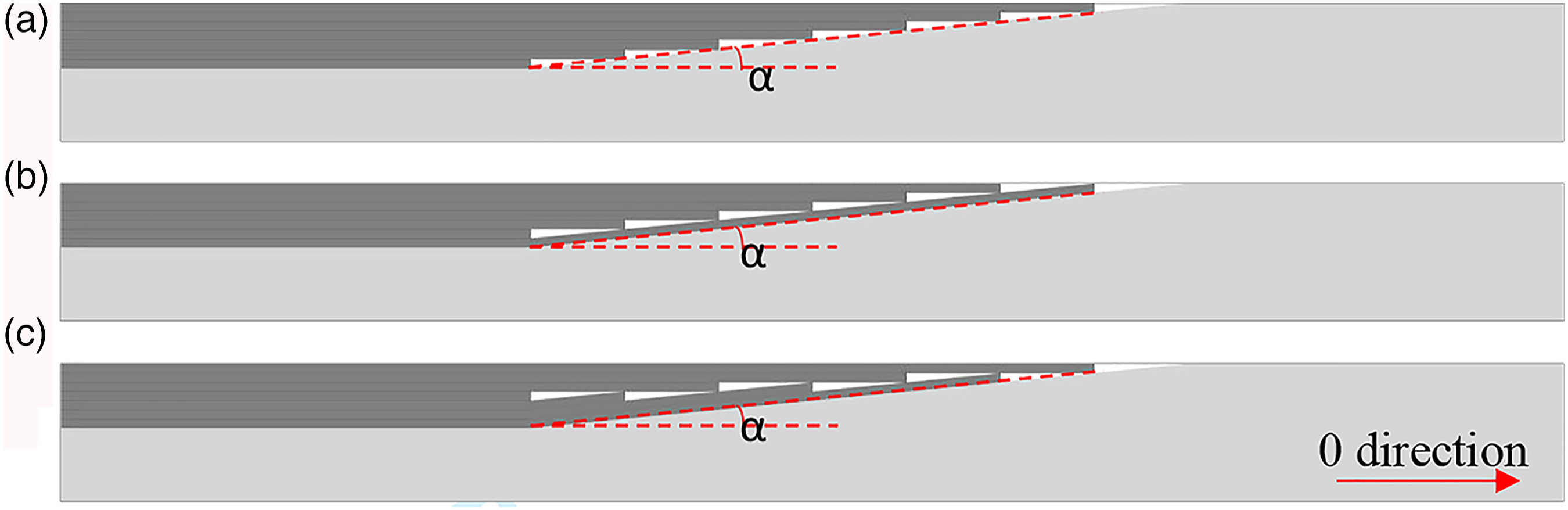
The most significant variables affecting the performance of a joint is the distance between each stepped ply or the gradient at the scarf. 21 Shallower taper angles (larger step size) reduce the thickness at each end of the joint, therefore minimising the magnitude of the peel stress.23,24 Similarly, the number of plies ending at any particular step should be limited to one, as increasing this number significantly reduces the tensile and flexural performance of the structure.25,26
This paper firstly aims to determine the potential mechanical performance gains from combining discontinuous DFC compounds with continuous fibre UD non-crimp fabrics. The successful application of these hybrid architectures for complex components depends on the ability to use local regions of UD fibre rather than full coverage plies. The second objective of this work is therefore to investigate a range of laminate designs to maximise the stress transfer within the transition zone (joint) between these dissimilar fibre architectures. A range of joint designs and ply step sizes are considered for different ply drop strategies, following aerospace guidelines. Electronic speckle pattern interferometry (ESPI) is used to study the surface strain distribution in the axially loaded joints.
Experimental procedure
Materials
CF-SMC material was produced using the DFC process outlined by Evans et al. 11 A 6-axis robot was used to direct the deposition of chopped Toray T700-50C 12 K carbon fibre tows onto a flat tool. Fibres were deposited to form a 500 mm x 500 mm square compound, using an east to west robot path followed by a north to south pattern to avoid a bias in the tow orientation distribution. 11 A 50 mm path offset was used in each spray direction and fibres were chopped to a length of 25 mm. An atomised jet of liquid epoxy resin was sprayed simultaneously with the fibres to partially impregnate them and hold them in place on the tool. The resin was a four-component epoxy resin from Huntsman: Resin XU 3508, Aradur 1571, Accelerator 1573 and Hardener 3403. The target areal mass of fibre for the DFC charge was 900gsm per millimetre (moulded plaque thickness). The areal mass of resin was 600gsm per millimetre, which yielded a fibre volume fraction for the charge of approximately 50%. Following resin B-staging (24 h at room temperature), the compound was trimmed using a die-cutter to 400 mm x 400 mm.
UD NCF was impregnated with the same liquid resin, using the same hardware as the DFC. This ensured that the matrix cure reaction and crosslinking was consistent between the dissimilar architectures. The UD NCF was FCIM356, 27 supplied by Hexcel, UK, which had an areal mass of 375gsm. The stitch yarn was polyester with a 1/2 pillar tricot stitch pattern and an areal mass of 7gsm. The fibre type was Toray T620-50C. The target areal mass of resin applied to each ply was 170gsm, which yielded a fibre volume fraction of approximately 60%.
Compression moulding
All plaques were moulded in a 405 x 405 mm square compression mould tool with a peripheral flash gap of 0.25 mm. A 1 mm/s closure speed was used for all tests. All plaques were moulded isothermally at 130°C for 30 min, followed by a 3.5 h freestanding post cure in an oven. The part thickness was controlled by the volume of material rather than using tool stops, to ensure the full 85 bar mould pressure was applied to the compound. All charges were prepared to provide 98% tool coverage throughout this work.
Layup strategies
Benchmark plaques
Monolithic plaques consisting of either 100% DFC or UD NCF were produced to provide benchmark material properties for the hybrid designs. The DFC material was randomly deposited to produce a net-shaped charge with a target fibre volume fraction of 50% and a final moulded thickness of 3 mm.
Symmetric hybrid plaques
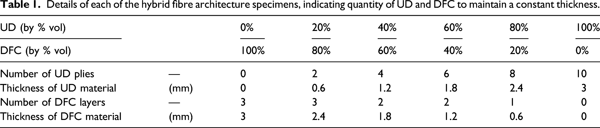
Details of each of the hybrid fibre architecture specimens, indicating quantity of UD and DFC to maintain a constant thickness.
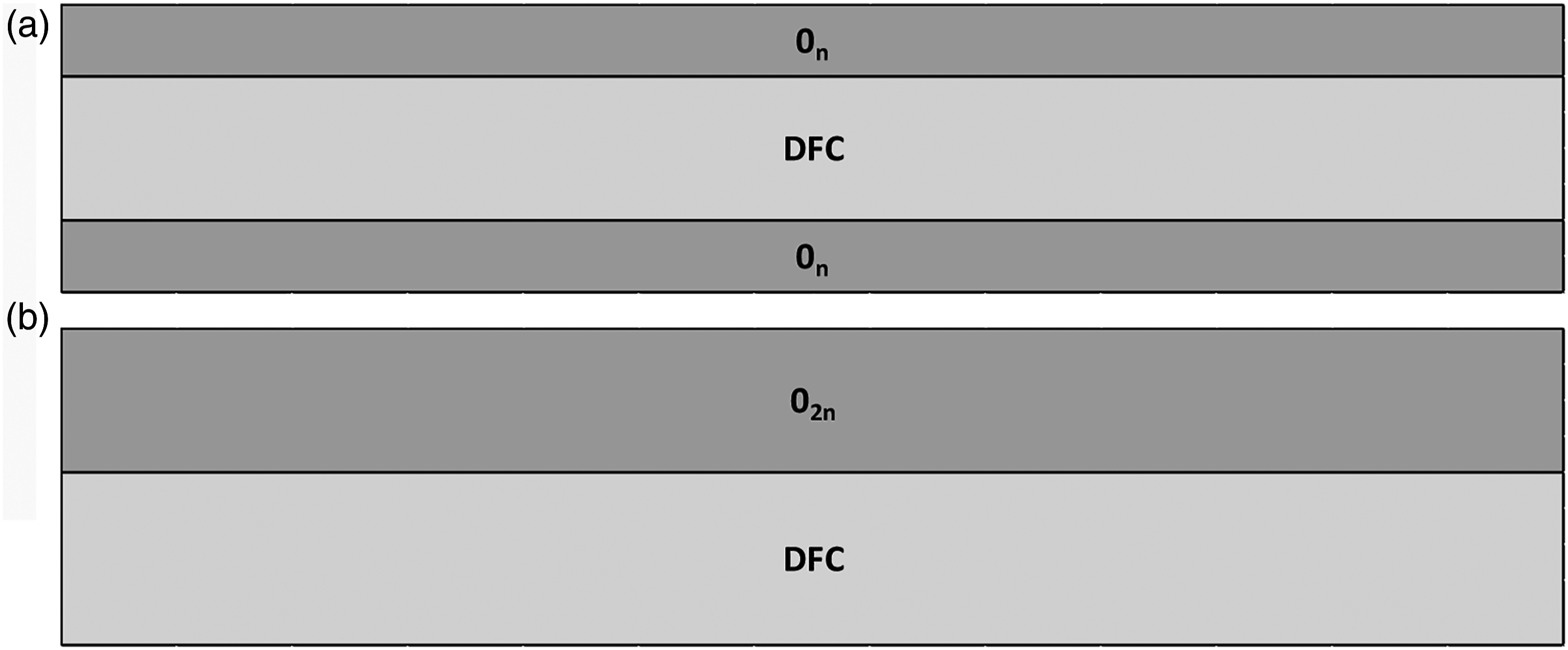
Hybrid fibre architecture schematics for (a) symmetric and (b) asymmetric arrangements.
Micrographs (2 longitudinal and 2 transverse) were obtained from each panel to assess the void content (%) and to verify the volume ratio of UD/DFC. The thickness of each constituent was measured at six locations per micrograph, which were determined to be within 5% of the target volume percentages for each material.
Asymmetric hybrid plaques
An asymmetric arrangement was also used to investigate the structural response of the hybrid architecture (UD/DFC), shown in Figure 2 (b), as it may not always be feasible to create symmetric laminates for complex components. This was produced by varying the volume content of UD and DFC material using the same manufacturing parameters provided in Table 1.
Hybrid joint plaques
Additional hybrid laminates were produced for the second part of the study, to investigate the design of the transition zone (joint) between the continuous UD fibres and the discontinuous DFC. These were divided into two groups to study 1) the effect of the step size and 2) the effect of the ply drop arrangement. Stepped joints were arranged so that each ply was incrementally shorter than the surface ply (Figure 1 (a)). The step length was increased as a function of the ply thickness, h, from 0 mm (all ply ends synchronised) to 1.5 mm (5h), 3 mm (10h), 6 mm (20h) and 12 mm (40h). Two alternative joint designs were used in addition to the stepped joint to investigate the effect of the ply drop arrangement. Tapered joints (Figure 1 (b)) had the longest UD ply positioned at the inter-material (UD/DFC) interface, which encapsulated the ends of the other UD plies. The alternating joint arrangement (Figure 1 (c)) was a combination of a stepped joint and a tapered joint, also moving the ends of the dropped UD plies away from inter-material interface, but encapsulating them with multiple plies at the interface.
The step size for all three geometries shown in Figure 1 was constant at 6 mm (20h). Each of these joints were configured with seven plies of 0° UD fabric, which were placed on top of a DFC charge with uniform areal density covering 100% of the tool surface. This ensured minimal global charge flow, limiting the local flow near the transition zone. Specimens were prepared to ensure the horizontal centre of the joint was always central to the loading rollers during flexural testing, as illustrated in Figure 3 Schematic of the location of the load roller during 3-point bend when testing in the (a) positive bending direction and (b) the negative bending direction.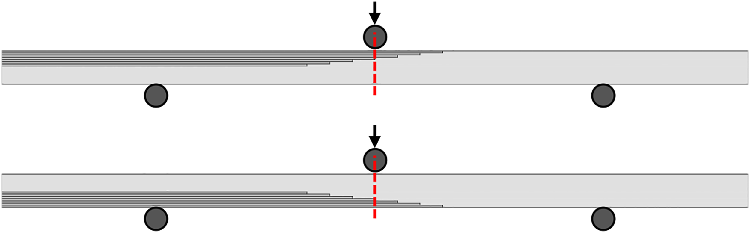
Test procedures
The in-plane material response of the symmetrical hybrid architecture was evaluated by tensile testing. This was conducted according to ISO 527-4: 1997. 29 Each tensile test specimen was 200 mm × 25 mm to provide a gauge length of 100 mm between the grips. Aluminium tabs, 50 mm long, were bonded to the ends of the specimen to prevent premature failure in the grip region. A clip-on extensometer with a 50 mm gauge length was used to measure the initial strain up to 0.4%, in order to calculate the tensile stiffness. The extensometer was removed once the strain exceeded 0.4%, after which the applied strain was calculated from the crosshead displacement. An extension rate of 2 mm/min was used throughout.
***The structural responses of the asymmetric hybrid laminates and the effect of the joint design were also characterised by flexural testing, according to ISO 14125:1998. 30 The dimensions of the specimens were the same as those used in the tensile testing and the loading rate was 2 mm/min, applied centrally between two Ø5 mm support rollers. The test standard recommends a different span length for the two constituent fibre architectures (e.g. 40 times the thickness for UD laminates and 16 times the laminate thickness for discontinuous materials), with no recommended span length for hybrid architectures. Therefore, a sensitivity study was performed to determine suitable span-to-thickness ratios for the DFC, UD and Hybrid specimens, in order to obtain representative flexural stiffnesses. The flexural moduli for all materials reached plateau values at (or before) a span length of 120 mm (40h), which was used throughout for all subsequent experiments. A Linear Variable Differential Transformer (LVDT) was used to accurately determine the flexural stiffness, measuring the central displacement from the underside of the specimen. Twelve flexural specimens were produced for each joint configuration, with six tested in the positive bending direction and six in the negative direction to investigate the effect of the asymmetry (see Figure 3 for definition of directions).
For tensile testing, surface strain distributions were obtained using electronic speckle pattern interferometry (ESPI), rather than DIC. ESPI provided higher resolution strain images over the long, thin area of interest (60 × 4 mm) compared to Digital Image Correlation (DIC). A key issue with DIC is the size of the pixel subset used for the correlation during data processing. The balance between spatial and strain resolution, means that Digital Image Correlation is generally limited in its ability to measure strains near to the edges of long, thin components.
The ESPI specimen was painted matt white to provide a monochromatic optically rough surface. A laser light was then reflected off the surface, which produced a speckle pattern that was captured by the video detector. The speckle pattern changed as the load was applied, which was used to quantify the strain distribution. Load was applied axially to the specimen at a rate of 1 mm/min, pausing momentarily every 200 N load, up to 5 kN, while the detector captured an image of the speckle pattern. The fringes resulting from the difference between subsequent images were used to calculate the axial strain (ɛ1).
Results and discussion
In-plane properties of symmetrical hybrid fibre architectures
The tensile stiffness and strength of the UD/DFC/UD hybrid specimens both increase linearly with increasing UD content, as shown in Figure 4. The baseline strength of 333 MPa ± 22 MPa for the isotropic DFC material (0% UD) increases by more than 110% with only 20% UD content, but the corresponding transverse strength reduces by 25%. In a similar fashion, the baseline stiffness of 38 GPa ± 3.2 GPa for the isotropic DFC material increases by 61% with 20% UD content, and the transverse stiffness decreases by 26%. (a) Tensile modulus and (b) strength of UD/DFC/UD hybrid carbon fibre architecture with increasing percentage of UD fabric by volume. Dotted lines indicate values produced by Rule of Mixtures.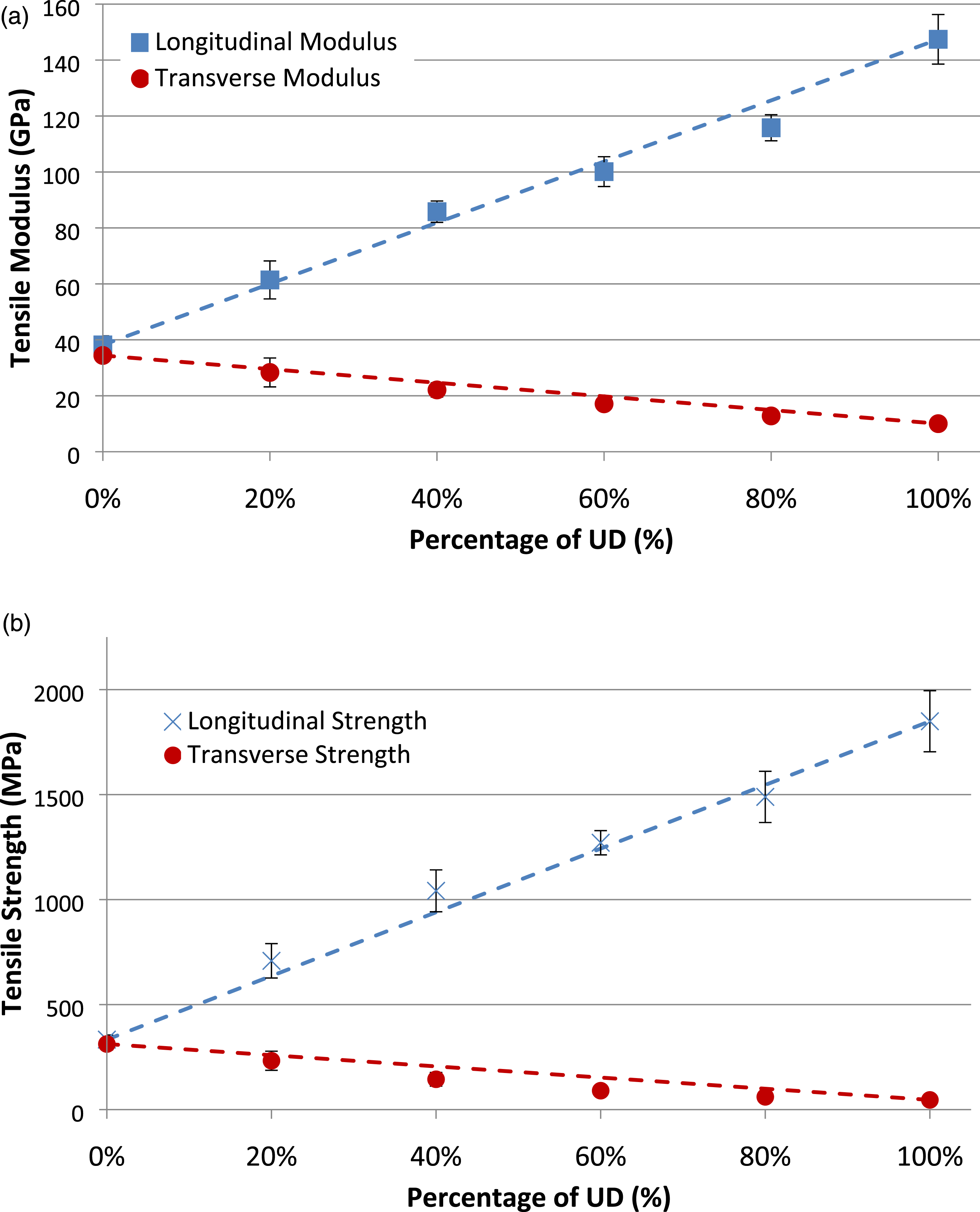
Failure of the hybrid fibre architectures occurs within three distinct regions: at the interface (either within the inter-laminar region between individual UD plies or at the inter-material interface between the dissimilar UD/DFC architectures), within the discontinuous fibre material or in the continuous fibre plies. In general, tensile failure within the discontinuous material is dependent on the fibre length. Fibre pull-out is common for shorter fibres lengths below the critical threshold, 31 but the 25 mm fibre length used here is greater than the critical length and therefore failure tends to occur due to a combination of fibre breakage and matrix failure. The larger surface area of the long fibre bundles enables higher shear forces to be transferred from the matrix to the fibres at the interface. 32 Due to the heterogeneous nature of the discontinuous fibre architecture, failure can be initiated by a stress concentration at the fibre bundle ends,2,33 hence the irregular surface at the fracture site.
The observed failure mode changes when a small quantity of continuous fibre fabric is added to the discontinuous fibres. This is because of the stiffness mismatch between the high stiffness UD architecture and the lower stiffness DFC architecture, generating a shear stress between the plies. The resin-rich interface between these two materials provides a low resistance path for a crack to propagate, 34 causing delamination.
Out-of-plane properties of asymmetric hybrid fibre architectures
The structural response of the asymmetric hybrid architectures [UD/DFC] was determined in bending for plaques with increasing quantities of UD fabric. Tests were performed in both positive and negative bending and the flexural stiffnesses and strengths are shown in Figure 5. Both the flexural stiffness and flexural strength increase linearly with increasing UD fibre content, in line with the observed behaviour in tension for the symmetric laminates. No significant difference was seen in the flexural stiffness for each of the bending directions, for either the longitudinal (fibres at 0°) or transverse samples (fibres at 90°), as shown in Figure 5(a). (a) Flexural modulus and (b) strength of asymmetric UD-DFC hybrid architecture under positive and negative bending (negative data points offset + 3% to improve clarity).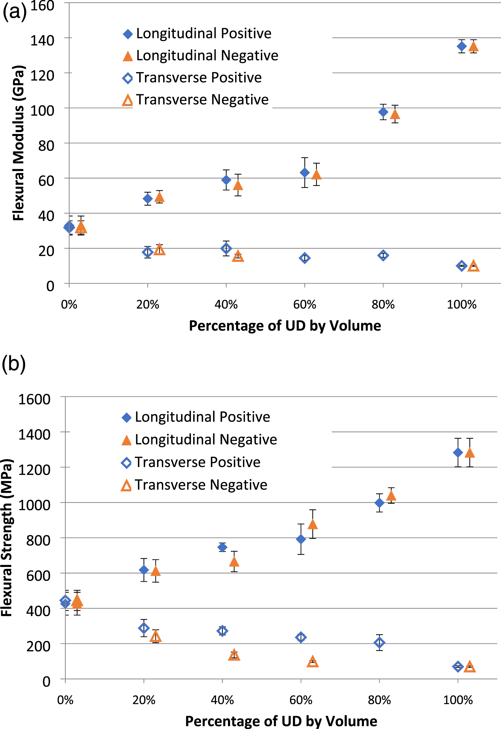
There is also no discernible difference between the positive and negative bending strength values in the longitudinal UD fibre direction, as shown in Figure 5 (b). However, whilst the average strength values in the two bending test directions were generally within 7%, there were visible differences in the failure mechanisms experienced for each sample. Example stress/strain curves in Figure 6 (a) indicate that longitudinal specimens tested in both bending directions exhibit initial linear elastic regions. However, in the positive direction, the peak stress coincides with a sudden tensile failure of the DFC material. In the negative direction, compressive failure occurs in the DFC material as the fibre bundles buckle. This results in a more progressive failure than in the positive bending direction as shown by the stress/strain curve in Figure 6 (a). Examples of flexural stress/strain curves for three-point bend tests of hybrid fibre architecture (40% UD content) in the (a) longitudinal and (b) transverse directions for positive and negative bending.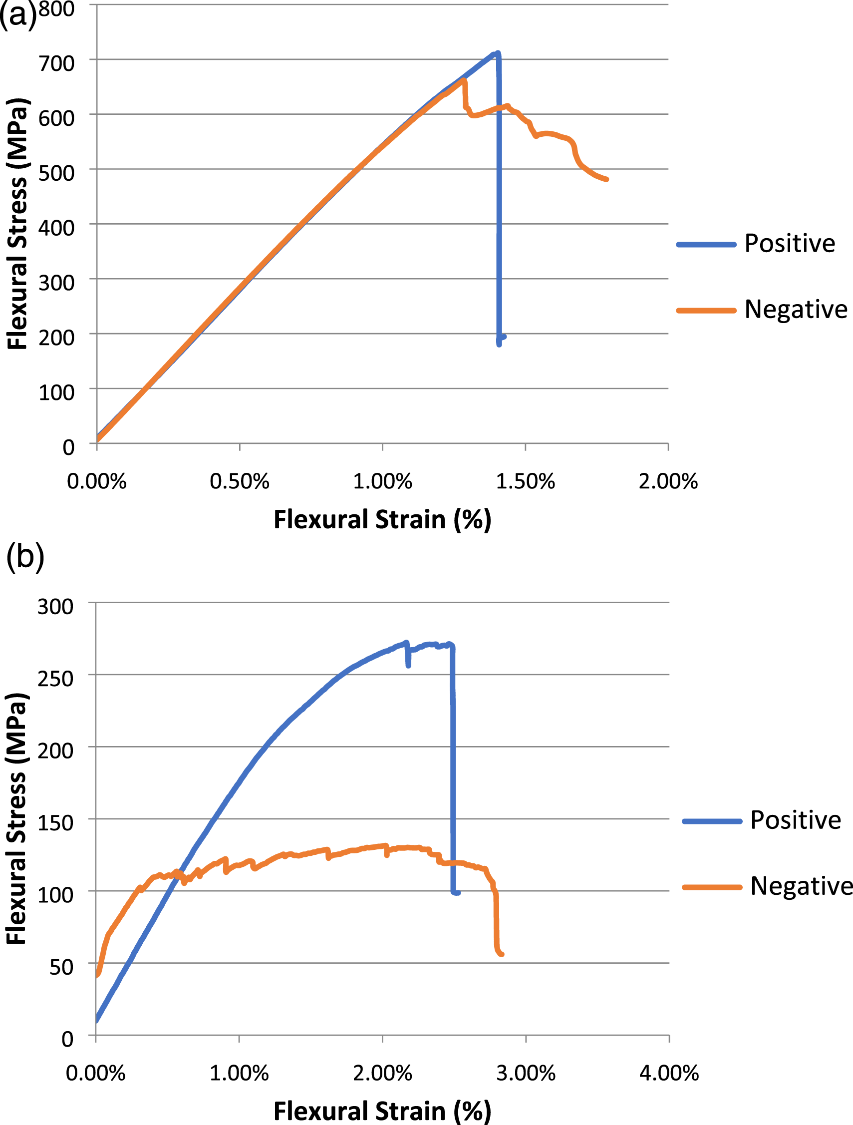
The transverse flexural strengths of the hybrid architectures with UD content between 40% and 60% are up to 58% lower in negative bending compared to the positive bending direction, as shown in Figure 5 (b). In the positive direction, load is primarily transferred through the stiffer discontinuous material rather than the low stiffness transverse bundles in the UD ply, as the resin-rich regions experience higher compressive strains. Figure 6 (b) indicates the damage growth during flexural testing of the specimens containing the transversely aligned UD fibres. Despite visible matrix damage on the compression loaded surface of the UD ply, load transfer on the tensile side for the positive bending case results in a linear stress-strain curve up to a strain value of ∼1.0%, followed by non-linear behaviour up to the point of final failure (flexural strains ∼2.5%). However, in the negative bending direction, visible macroscale cracks initiate at a much lower strain (<0.5%), which propagate between tows through the thickness from the continuous fibre surface. This significantly reduces the capability to carry the in-plane load and progressive damage growth can be observed from the flexural stress/strain curve.
Joint design: Effect of step size
Microstructure
Micrographs were taken from coupons produced with different step sizes (Figure 7) to study the inter-material interface between the unidirectional plies and the discontinuous DFC. There is significant ‘swirling’ of the discontinuous fibres for the hybrid plaque with a step size of 0 mm (Point 1 in Figure 7 (a)), as a result of charge flow in the 0° direction caused by the addition of the continuous material. Similar swirling was also observed in a previous study when the charge coverage for a DFC plaque was reduced to just 40% of the tool area[11], but it is exacerbated here as the discontinuous fibres are encouraged to flow over a steep change in gradient at the end of the UD ply stack. This gradient is reduced as the step size increases, therefore the level of swirling is noticeably lower in the DFC material for longer step sizes, as shown in Figures 7 (b) and (c) for the 1.5 mm and 3 mm step sizes, respectively. Micrographs (5x magnification) of stepped unidirectional/discontinuous carbon fibre joints produced by co-compression moulding. Step sizes (a) 0 h, (b) 5 h and (c) 10 h. Point 1 indicates fibre swirling and Points 2 and 3 indicate some locations of resin richness at the end of each ply drop.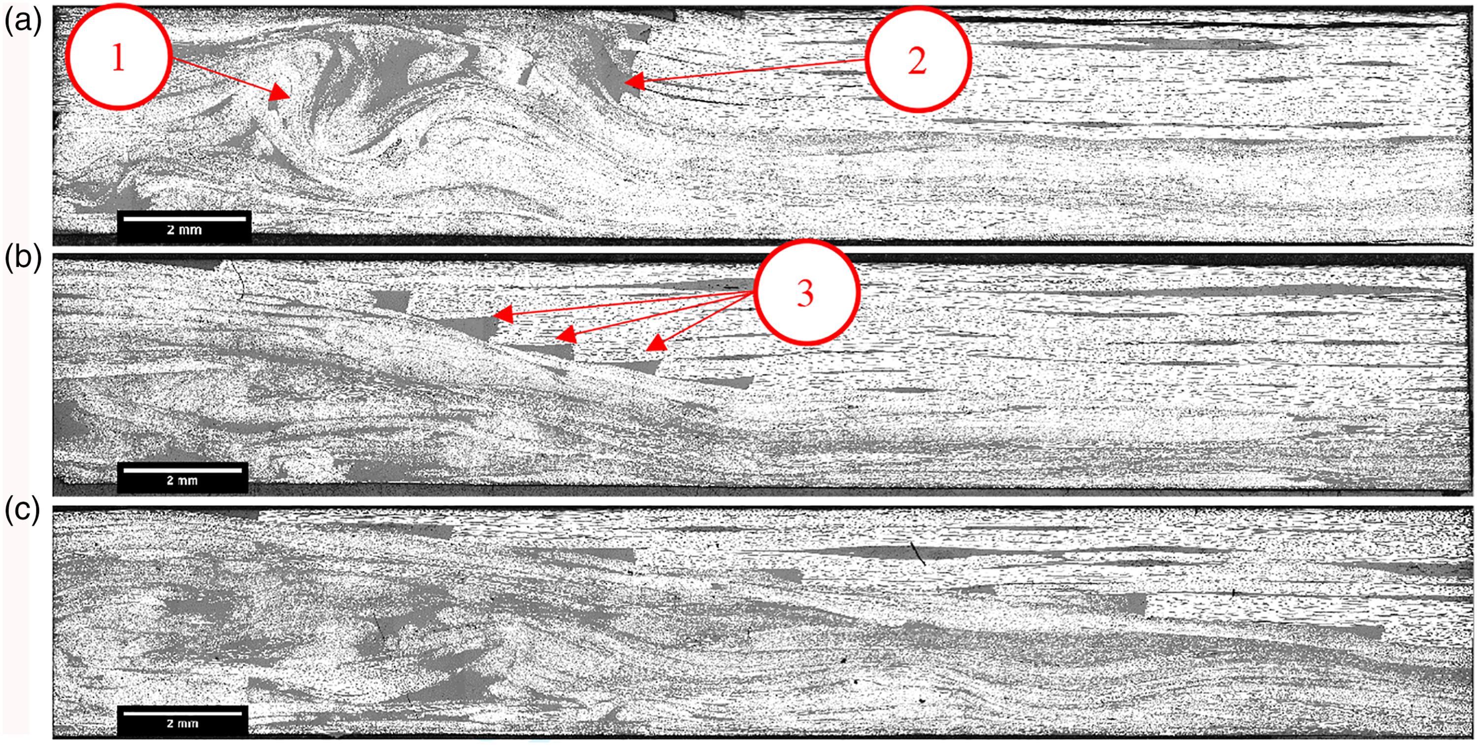
A resin-rich region was noted at the end of each ply drop (Points 2 and 3 in Figures 7 (a) and (b)). The shape of the resin-rich region varies depending on the orientation of the discontinuous fibre bundle bridging the end of the continuous fibre ply. Fibre bundles parallel to the flow direction along the joint are unable to nest effectively at the ends of the continuous plies. These form large, triangular resin-rich pockets between the continuous and discontinuous materials. Using ImageJ analysis software, the length of these was measured for the 20h and 40h step sizes. The average length was found to be 1.57 mm (±0.37 mm), with the largest being 2.1 mm, 7 times the ply thickness. The maximum step length (40h = 12 mm) is less than half the length of the average discontinuous fibre (25 mm); therefore, resin-rich pockets are common at the end of each ply drop. Whilst some transversely orientated fibre bundles appear to fill some of these regions, the effect is negligible since the transverse properties of the bundles are similar to the properties of the bulk matrix material; therefore, the magnitude of the stress concentration is generally unaffected.
Mechanical performance
The tensile stiffness of the stepped hybrid plaques increases linearly with increasing step length. The stiffness of the hybrid material only exceeds the stiffness of the monolithic DFC baseline (36.3 GPa ± 3.3 GPa) at a step size of just above 5h (step length of 1.5 mm), as shown in Figure 8. The tensile strength of the stepped hybrid plaque increases linearly from 120 MPa to 200 MPa from 0h to 20h, but appears to level off at 40h (218 MPa ±39 MPa), which is 67% of the DFC baseline (323 MPa ± 27 MPa). This is partially due to the large stress concentrations that exist at the ply ends, but partly because of the asymmetric laminate design. This asymmetry causes a complex stress state through the thickness of the laminate due to the introduction of a bending moment caused by the stiffness mismatch of the continuous and discontinuous materials. A crack propagates along the resin-rich path at the joint interface at the end of each ply step. An overall trend can be distinguished however, as the tensile stiffness and strength generally increase linearly with increasing step size. Tensile strength and stiffness of UD/DFC stepped joints for varying step size. The horizontal red line indicates the tensile modulus of the DFC material (36.3 GPa ± 3.3 GPa) and the horizontal blue line indicates the tensile strength of the DFC material (323 MPa ± 27 MPa).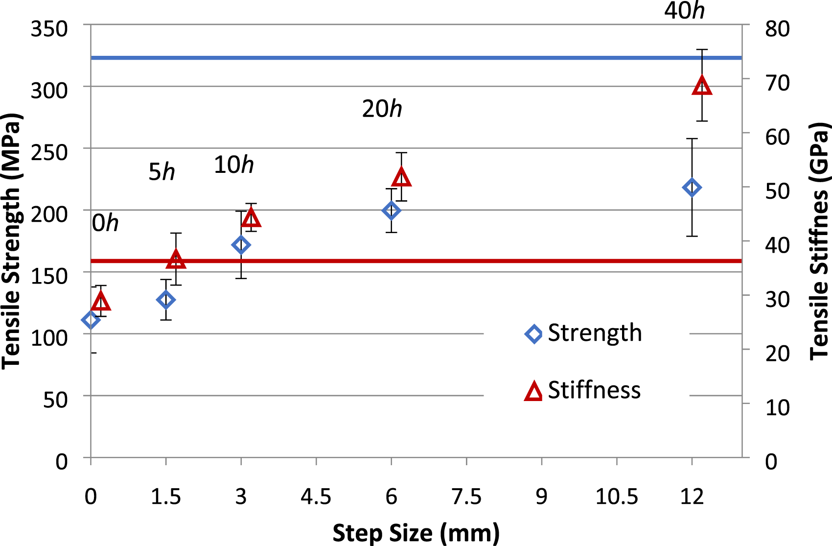
The flexural properties of the stepped joints have also been compared to the baseline DFC values (Figure 9). The flexural stiffness increases linearly with increasing step size. The step size must also be greater than 5h (step length of 1.5 mm) to maintain a higher flexural stiffness than the DFC material for the materials studied. However, the step size must be greater than 20h (step length of 6 mm) for the flexural strength of the stepped joint to exceed the baseline value for the monolithic DFC plaque. This is considerably larger than the recommended minimum distance of 8h commonly used for UD materials in aerospace designs.23,24 Flexural properties of UD/DFC stepped joints in positive and negative bending for varying step sizes. Horizontal lines indicate DFC baseline at 32.4 GPa ± 4.6 stiffness and 435.5 MPa ± 60.4 strength (negative bending points are offset by + 0.25 mm to improve clarity).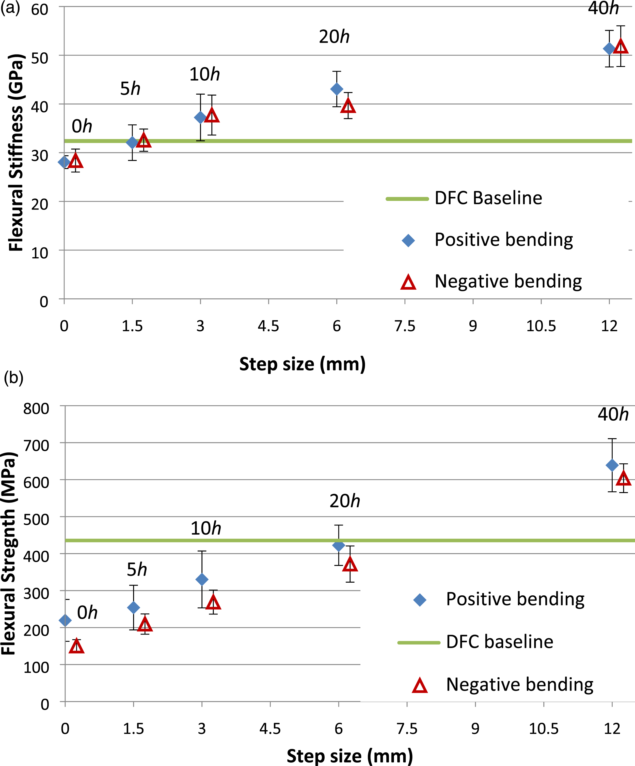
Whilst there was no significant difference between the positive and negative bending directions in terms of flexural stiffness, the flexural strengths (Figure 9 (b)) were affected due to a change in failure mechanism. During positive bending, the UD fibres on the upper surface were in compression and failure occurred due to tension in the DFC material. For shorter step sizes of less than 20h, most failures occurred away from the joint because of the non-uniform bending moment caused by the asymmetric laminate (Figure 10 (a)). As the step size increased, the failure region moved closer to the loading point, causing buckling in the UD laminates and some delamination (Figure 10 (c)). However, in negative bending, tension in the UD fibres increased the stress in the resin-rich region at the end of the surface laminate. As this resin-rich region failed, the crack propagated along the boundary between the continuous and discontinuous fibres (Figures 10 (b) and (d)). This change in failure mechanism reduced the flexural strength by 50 MPa in the negative bending direction compared to the positive direction. The influence of the bending direction is reduced as the step size is increased. Examples of failure mechanisms for step size 5 h (1.5 mm) in (a) positive and (b) negative bending directions, and step size 20 h (6 mm) in (c) positive and (d) negative bending directions.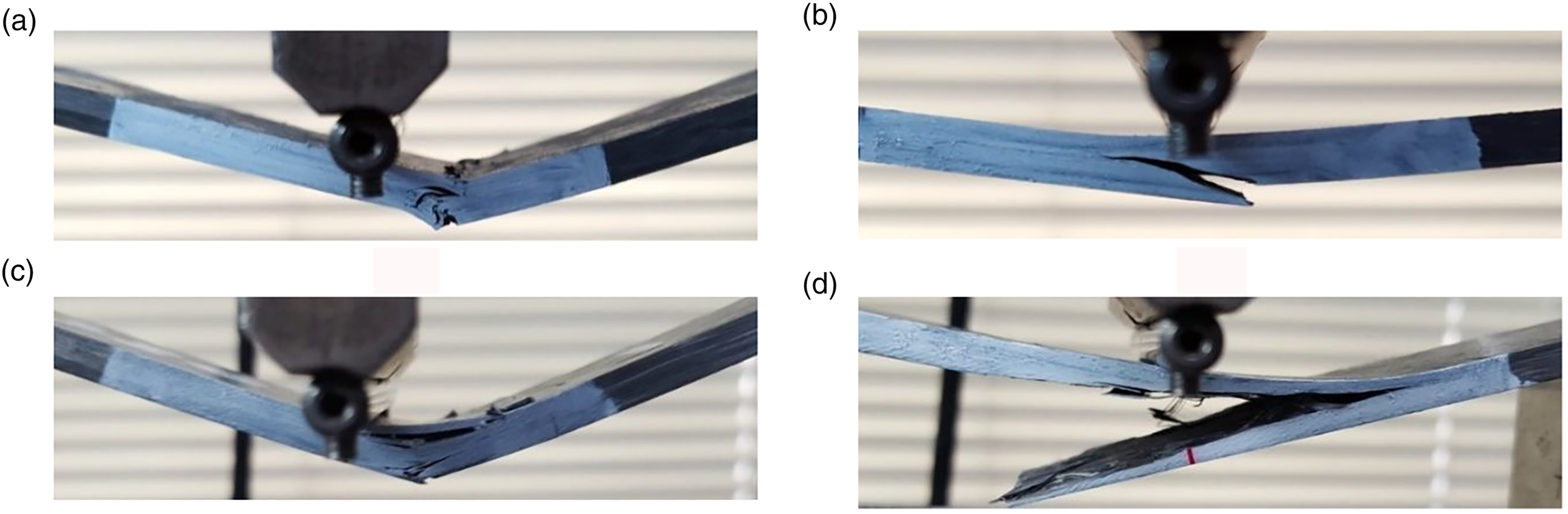
Strain distribution analysis
Strains were obtained for each of the step sizes by applying a 5 kN tensile load via ESPI. The surface strain distribution is relatively uniform within the UD material, while the strain distribution in the DFC material is significantly varied, reflecting the heterogeneous fibre architecture, as shown in Figure 11. EPSI axial strain results for DFC/UD hybrid architecture. Stepped joint with a step size of 20 h (6 mm). (a) The average strain across the width of the specimen (y-direction) with respect to the position along the length (x-direction). x = 18 mm indicates the start of the step geometry, x = 24 indicates the end of the step, where x≥ 24 is the region of UD fibres. (b) The front surface of the specimen, where the unidirectional fibres are on the visible surface, under 5 kN axial load (x-direction). The field of view was 60 mm × 25 mm.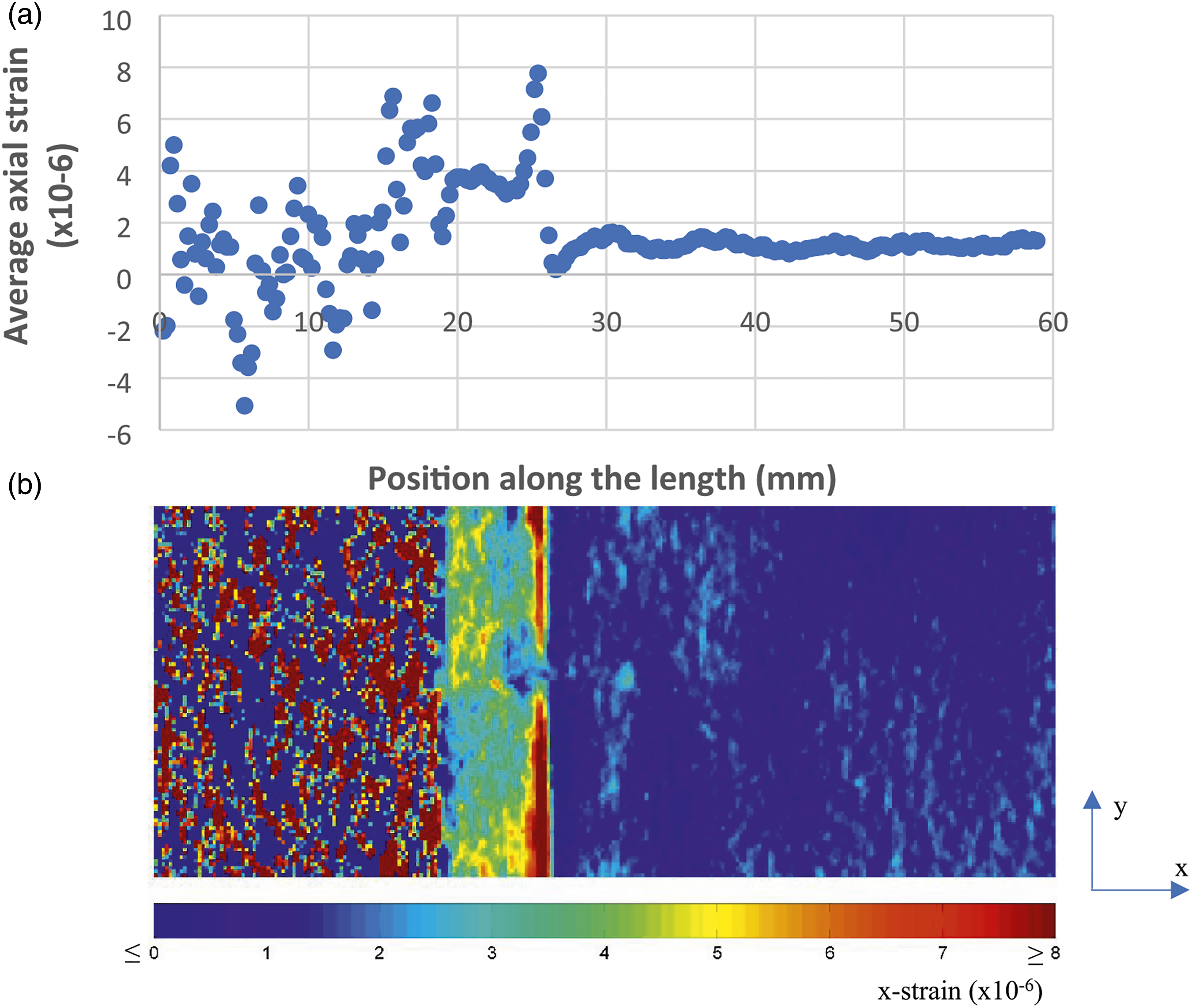
According to the side view of the specimens in Figure 12, strain concentrations can be observed at the end of each ply drop, as the joint transitions from the high stiffness UD material to the lower stiffness DFC material. The greatest of these strain concentrations tends to be located at the end of the surface ply. The largest of the axial strains is seen within the 0h specimen where all ply ends are synchronised. The magnitude of the axial strain at the end of the surface ply reduces by approximately 60%, from 38 microstrain to 15 microstrain as the step size increases from 0 mm to 1.5 mm (5h) (for an applied load of 5 kN). Axial strain (x-direction) distribution via ESPI (results taken from 60 mm × 4 mm region of interest, 5 kN axial load). Step joints: 0h, 5h, 10h, 20h and 40h and tapered joint: 20h. (Note the different axial strain scale for the 0h specimen).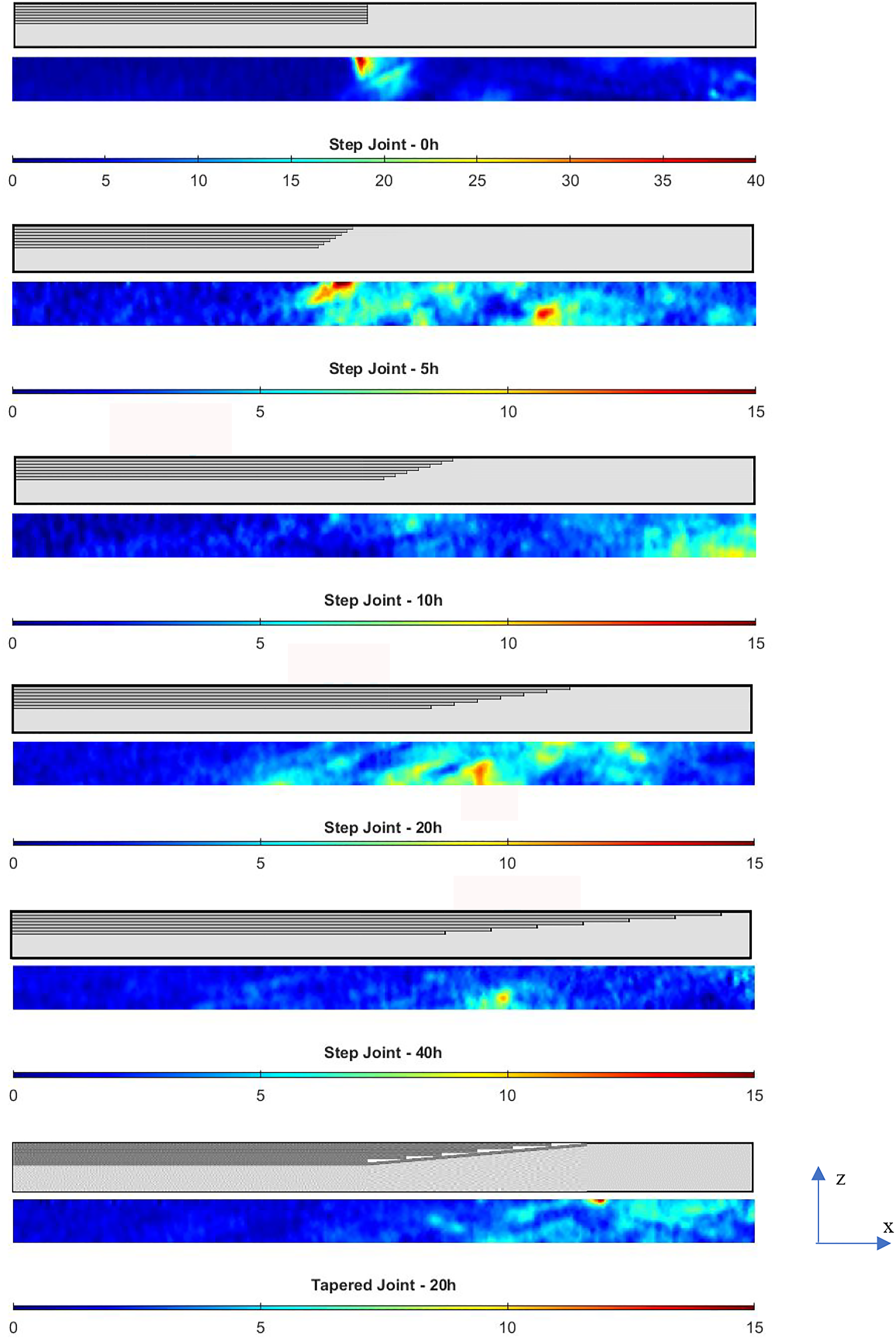
Figure 12 also shows that the magnitude of the strain concentration in the ply drop area is comparable in magnitude to the inherent material strain concentrations within the DFC material (8–10 microstrain), which are caused by the bundle ends.2,33 As the step size tends towards 20h, the joint does not cause a critical stress concentration and failure is likely to occur in the bulk DFC region, as shown by Figure 13. The tensile results reported for these hybrid material coupons are therefore in line with the aerospace design guidelines for ply drops within UD prepreg layups, which suggest that the joint angle should not exceed 723,24 (a step size of 8h or greater) in order to minimise the strain raisers that form at the end of each ply drop. Failure of a tensile specimen with a step size of 20h (6 mm), where failure occurs within the DFC region away from the joint.
Joint design: Effect of joint geometry
The design of the joint (stepped, tapered or alternating (Figure 1)) was varied to change the position of the ends of the dropped UD plies in relation to the discontinuous/continuous fibre interface. The aim was to reduce the grouping of ply ends near to the DFC/UD interface to minimise stress concentrations. The tapered and alternating arrangements only had one and two ply drops at the DFC/UD interface, respectively. The remaining plies were all enclosed by other plies, where micrographs showed large, triangular resin-rich formations at the enclosed ply ends, as indicated in Figure 1 and Figure 14. Micrographs (5x magnification) of different joint configurations with a step size of 20h: (a) stepped, (b) tapered and (c) alternating. Red dotted lines indicate UD/DFC interface. UD plies are above the dotted line and DFC material is below in each case.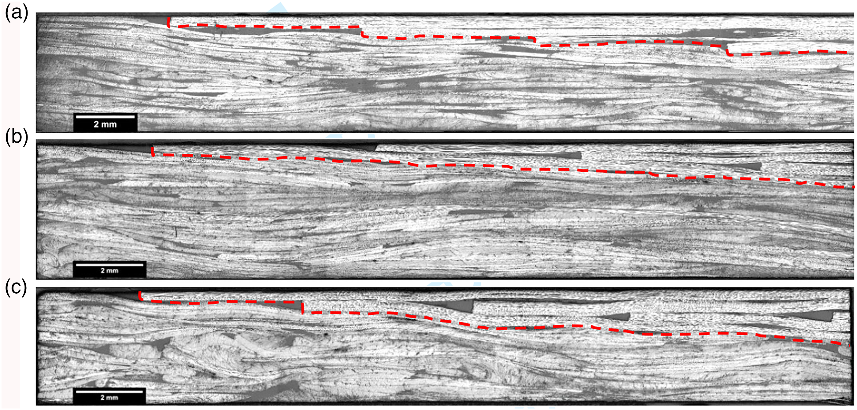
The flexural stiffnesses of the tapered and alternating geometries are shown in Figure 15 (a). All hybrids demonstrated a greater stiffness than the DFC benchmark in positive and negative bending. There is a statistically significant (p < 5%) increase in stiffness in the negative bending direction (UD plies in tension) as the joint design changes from stepped to tapered (13% increase) or alternating (21% increase) geometries. In the positive bending direction (UD plies in compression), the flexural stiffness is similar for both the tapered and alternating geometries, but there is a statistically significant (p < 5%) difference between the tapered joints (8% increase) and the stepped joints. The flexural properties of UD-DFC joint with varying geometry compared to the DFC baseline (stiffness: 32.4 GPa ± 4.6 and strength: 435.5 MPa ± 60.4).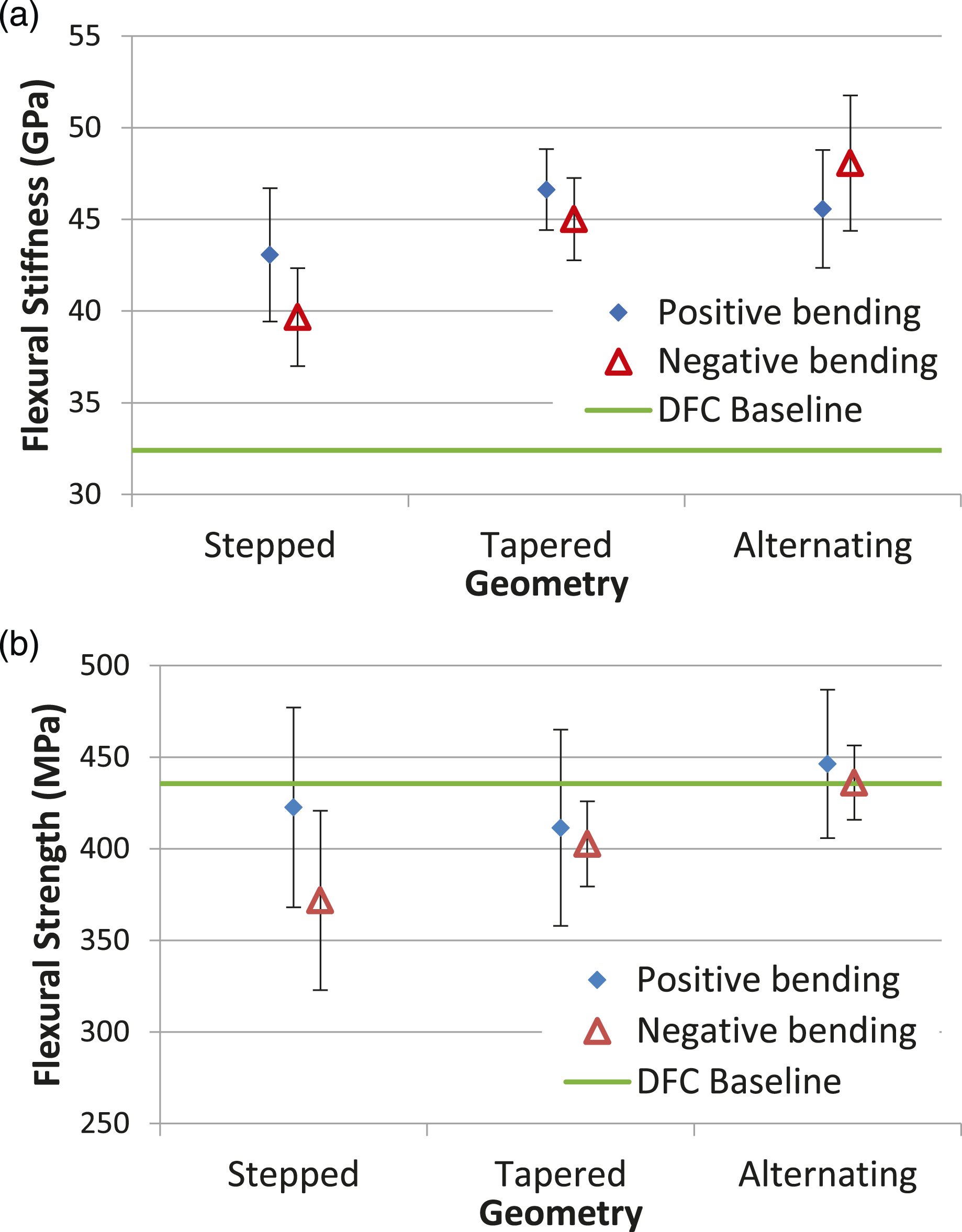
Tapering the joint reduces the stress concentration at the joint interface compared to a stepped joint. All seven ply ends are in direct contact with the DFC material at the inter-material interface for the stepped joint, whereas tapered joints only have one ply end at the joint interface, with the remaining ply ends at least one ply thickness away, as indicated by Figures 1(b) and (c). According to the ultimate flexural strengths in Figure 15 (b), joint design did not have a significant effect in positive bending, with no distinguishable difference between the stepped joint and the tapered joint. However, in negative bending, there was an 8% increase in flexural strength for the tapered geometry compared to the stepped geometry, which is considered to be statistically significant (p < 5%).
The alternating joint contains two ply ends at the inter-material interface, but the other ply ends are up to 0.9 mm (3 times the ply thickness) away from the interface. Within the alternating joints, the greatest number of continuous fibres therefore interrupts any cracks that grow between the ply ends and the interface, preventing crack propagation along the joint interface. This results in a statistically significant increase under negative bending (p < 5%) compared with the stepped joints (17% increase), with a small increase also observed in the positive bending direction (6%). Changing the geometry of the joint therefore reduces the difference between the positive and negative flexural strengths from 50 MPa to approximately 10 MPa, whilst approaching the flexural strength value of the baseline DFC material.
There was no discernible difference between the tensile stiffnesses for the three geometries (graph not included). In addition, the tensile strength exhibited a marginal increase from 199.5 MPa ± 17.7–213.2 MPa ± 11.3 when changing from the stepped joint to the tapered joint, this increase was within the level of error observed for each case, so was considered to be statistically insignificant.
ESPI was used to further inspect the strain distribution of the tapered geometry compared to the stepped joint of equal length (20h). Tapering the joint resulted in no change in axial strain at the end of the surface ply (∼9 microstrain) (Figure 12). However, enclosing all ply drops away from the joint interface reduces the axial strain concentrations in the triangular resin-rich regions at the end of each sub-surface ply by approximately 50% to five microstrain compared to the stepped equivalent. The tapered joint therefore improves the load transfer between the DFC and the stiffer UD material by moving the critical resin-rich regions at the end of the dropped plies away from the inter-material interface.
Conclusions
The concept of hybridising discontinuous fibre composites with unidirectional materials has been studied as a potential solution for producing cost effective structural composite materials with short cycle times (5–10 min). Local patches of UD fabric have been added to discontinuous fibre moulding compound to locally increase mechanical performance, but the key to successful implementation within real structures is in understanding the stress transfer from one material to another within the transition zone (joint).
The first objective of this paper was to establish the effect of varying the volume ratio of UD to DFC on the tensile and flexural properties, for both symmetric (UD/DFC/UD) and asymmetric arrangements (UD/DFC). In-plane mechanical testing of symmetrical hybrid laminates (UD/DFC/UD) has established that the strength and stiffness generally follow an expected linear relationship with increasing volume content of continuous fibres within the laminate. The tensile stiffness and strength of a composite with a hybrid fibre architecture were found to be 60% and 110% higher, respectively, than the baseline discontinuous fibre moulding compound, when just 20% (by vol.) of UD fibres were aligned in the primary loading direction.
Asymmetric hybrid laminates have been considered to avoid compromising the cycle time offered by the compression moulding process. Only local additions of UD material were added to the otherwise random discontinuous fibre material, exhibiting similar flexural properties in both the positive and negative bending orientations when the UD fibres were aligned in the longitudinal direction. However, they experienced different failure modes in the two test directions, where failure in the positive bending direction with the UD plies on the uppermost surface was sudden, with a near linear elastic stress/strain curve. The failure for the negative bending direction was more progressive, due to compressive failure of the DFC material.
The second objective of this work was to investigate a range of laminate designs to maximise the stress transfer between the continuous UD fibres and discontinuous DFC in the transition zone, in order to prevent failure in the joint region due to stress concentrations. For conventional stepped designs where each ply was incrementally shorter than the surface ply, failure was initiated at the end of the joint due to resin-rich regions located at the end of the surface ply under axial and bending loads. Within the elastic limit, strain concentrations were reduced by 75% as a result of increasing the step size from 0 mm to 3 mm (10 times the ply thickness). The magnitude of this strain concentration remained constant as the step size was increased further, which supports the application of the aerospace ply drop and joint guidelines published in the literature21–24 for these hybrid laminates. This confirms that the taper angle at the joint should not exceed 7 (step size of ∼8h). However, the bending results indicated that the flexural strength of the hybrid laminate was lower than the strength of the DFC baseline up to a step size of 20 times the ply thickness. When the step size is greater than 20h, the local axial strains within the random DFC architecture are larger than the strain concentrations at the end of the ply drops, resulting in failure away from the joint interface within the bulk DFC material.
Changing from a stepped joint to an alternating joint, where the ply drops are further away from the inter-material interface, increased the bending strength in the negative direction (UD plies in tension) by 18%, from 371 MPa to 436 MPa. Introducing a continuous unbroken ply at the inter-material interface for the tapered and alternating step joint designs reduces the strain concentrations at the ply ends in comparison to the inherent material stress concentrations in the DFC material, reducing the likelihood of failure at the interface.
Footnotes
Acknowledgements
This work was supported by the Engineering and Physical Sciences Research Council [grant number EP/T006420/1], using equipment within the High-Volume Composites Manufacturing Cell with Digital Twinning Capability.
The authors would also like to acknowledge financial support from the Ningbo S&T Bureau for the Ningbo International Collaboration Project (project code 2017D10033), ‘R&D of Lightweight High Strength SMC materials’.
Declaration of conflicting interests
The author(s) declared no potential conflicts of interest with respect to the research, authorship, and/or publication of this article.
Funding
The author(s) disclosed receipt of the following financial support for the research, authorship, and/or publication of this article: This work was supported by the Ningbo Municipal Bureau of Science and Technology (2017D10012), Engineering and Physical Sciences Research Council (EP/T006420/1).