
Abstract
Technical textiles have the ability to deform under load by shearing, which distinguishes them from thin sheet materials such as paper. This particular property helps them to deform and take the shape of the complex part that they were intended to create. Draping, flexibility and handling of technical textiles are greatly affected by their shearing behaviour. In this paper, the influence that factors such as stitch (i.e., presence or absence of it), testing speed and the pre-tension force applied have on the shear behaviour of 0/90∘ technical textile is studied to form a reference test. To achieve this, 0/90∘ technical textile samples in two different forms are prepared and subjected to the Trellis picture frame test. It was observed that the presence of stitch greatly affected the critical shear angle and the maximum shear force experienced by the textile. Increase in testing speeds and pre-tension force also increased the shear force experienced by it. However, the critical shear angle decreased with the increase in testing speed, while the value of pre-tension force applied had no effect on the critical shear angle.
Introduction
In recent years, there has been a considerable increase in the use of composite materials. They are being used in a wide variety of applications, ranging from automotive to wind energy to aerospace industries.1–3 Composite parts with geometrically intricate shapes are generally manufactured by using Non-Crimp Fabric (NCF) preforms. NCFs are technical textiles (In this paper, NCFs are referred to as technical textiles), which have several layers of differently oriented unidirectional fibre rovings stacked on top of one another and are held together by means of a stitch (usually polyester). They were developed with the objective of obtaining a technical textile which has a high degree of freedom in the direction of fibre orientation and with minimum crimp. 4
It is a well-known fact within the field of composite manufacturing that the extent to which a technical textile can be used mainly depends on its ability to drape a onto the mould. 6 In order to predict this draping accurately, it is necessary to have knowledge about the shear behaviour of the technical textile. 7 The Trellis Picture Frame Test (hereafter referred to as picture frame test)7–10 is one of the important tests used to determine the shear behaviour of technical textiles as it induces pure shear uniformly throughout the sample. Thus, allowing for the direct extraction of the shear force values. However, the picture frame test suffers from the disadvantages of clamping and alignment problems when placing the textile into the frame in addition to fabric wrinkling. 11
In the process of addressing the problem of fabric wrinkling associated with the picture frame, Long Li et al. 12 conducted experiments in which pre-tension in the form of dead weight hanging down on the fabric was applied to make the rovings/yarns parallel to each other. The application of the pre-tension force served its purpose but also led to a considerably deviated result in the first shearing cycle when compared to the results from second and third cycle. This deviation was attributed to disturbances and tension experienced by the fibers during the first shearing cycle. After the first cycle, the fibers were reported to have been “conditioned” and hence, the results of the second and third cycle were almost similar. Therefore, the results from the second and third shearing cycle were used to characterise the shear behaviour of the material.
Mei et al.13,14 designed a picture frame which coupled both the shearing and the pre-tension force application process. Each sample in the test was subjected to three cycles and the results from the first cycle were again considerably deviated from the second and third cycle. However differently, they attributed the deviation to the over tension exerted on the stitching thread which resulted in them being snapped and causing irreparable damage to the technical textile. This irreparable damage caused during cycle 1 adversely affects the shear response of the technical textile carried out during cycle 2 and cycle 3. Thereby suggesting that, each sample can be subjected to shear test only once and the data from this test has to be used to characterise the shear behaviour of the material. The same was also reported by Chen et al. 15 They also showed that with the increase in the pre-tension force, the ability of the yarn to resist lateral deformation increased. However, only one repetition was carried out for each pre-tension value and hence, the variability of the results were not reported. Both these works, attempted to solve the problem of fabric wrinkling by applying pre-tension force directly while carrying out shear tests which makes them complicated to implement on an Universal testing Machine (UTM). Also, the problems of clamping and alignment of the textile when placing it into the picture frame still remained.
Apart from the above mentioned works, there have also been many studies that have analysed the shear behaviour of technical textiles6,10,16–25 but, there is no standardised test for analysing the same. Also, there is insufficient data available on the type of sample to be used (i.e. samples with or without stitch) as the sample preparation time varies hugely, depending on the type of sample selected or the speed at which the test has to be conducted or the amount of pre-tension force (which solves the problem of fabric wrinkling) that has to be applied.
Hence, this study is aimed at investigating the influence that factors such as stitch (presence or absence of it), the speed at which the test is conducted and the amount of pre-tension force applied have on the shear behaviour of the technical textile using a Trellis picture frame. From the results obtained, a reference shear test is proposed. In the context of this paper, a reference test can be defined as a test along with its test parameters that is proposed based on the outcome of the study conducted. This proposed reference test can then be used by other researchers to carry out shear test of 0/90∘ technical textiles as there is no standardised way of doing the same. Also, in this paper a simple solution is proposed for the application of the pre-tension force using a pre-tension apparatus that tries to solve the above mentioned problems associated with the picture frame. 26 This will be explained in detail in subsection, “Pre-tension apparatus”.
The paper is constructed such that, the material used for testing is initially described in section “Experimentation”, this is followed by a detailed description of the picture frame test experimental procedure. The results obtained from the testing are discussed in section “Results and Discussions”. The reference test parameters are proposed in the section, “Proposal of a Reference Test”. The paper concludes by reviewing the results obtained during the course of this study in section “Conclusions”.
Experimentation
This section briefly describes the material used for this study. Then, we explain how the samples were prepared. The placement of the textile into the picture frame using a pre-tension appartus is described later. The section concludes by giving an insight into the experimental procedure of the test.
Materials and method
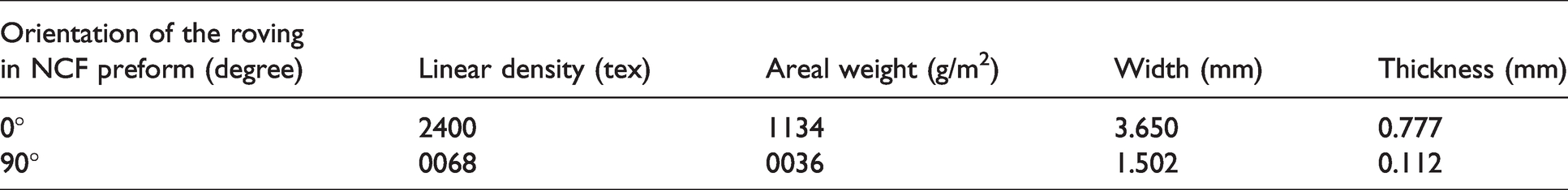
Unidirectional NCF which consists of 2400 and 68 tex rovings manufactured by SAERTEX b was subjected to the experiment described in this paper, i.e., the picture frame test. This particular material was chosen for testing as the work conducted here is a small part of the project,” PROSIM R” which deals with creating a virtual process chain to automate the process of rotor blade production. The technical textile used has a tricot stitch and the properties of the rovings used to manufacture it, i.e., 2400 and 68 tex rovings can be found in Table 1. Figure 1 shows the constituents of the technical textile used.
Details of the rovings used to manufacture the technical textile.
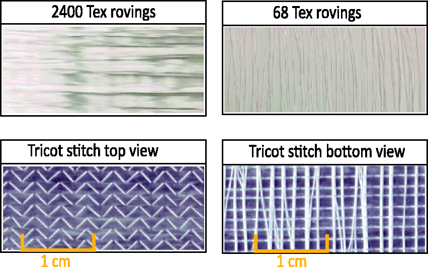
Constituents of the technical textile used.
The thickness of the rovings were measured according to the European standard ISO 5084: 1999. 27
Sample preparation
The material used in this study is a unidirectional NCF with majority of its areal weight being in the direction of 2400 tex rovings, while the 68 tex rovings act as stabilisation rovings. Both these rovings are positioned perpendicular to each other. The samples were prepared such that they had a dimension of 300 mm × 300 mm with the central quadrilateral area having a dimension of 150 mm × 150 mm. Figure 2 shows a graphical representation of the sample along with its dimensions and the quadrilateral test area.
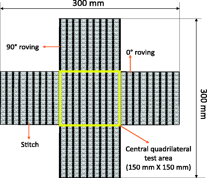
Graphical representation of the sample along with its dimensions.
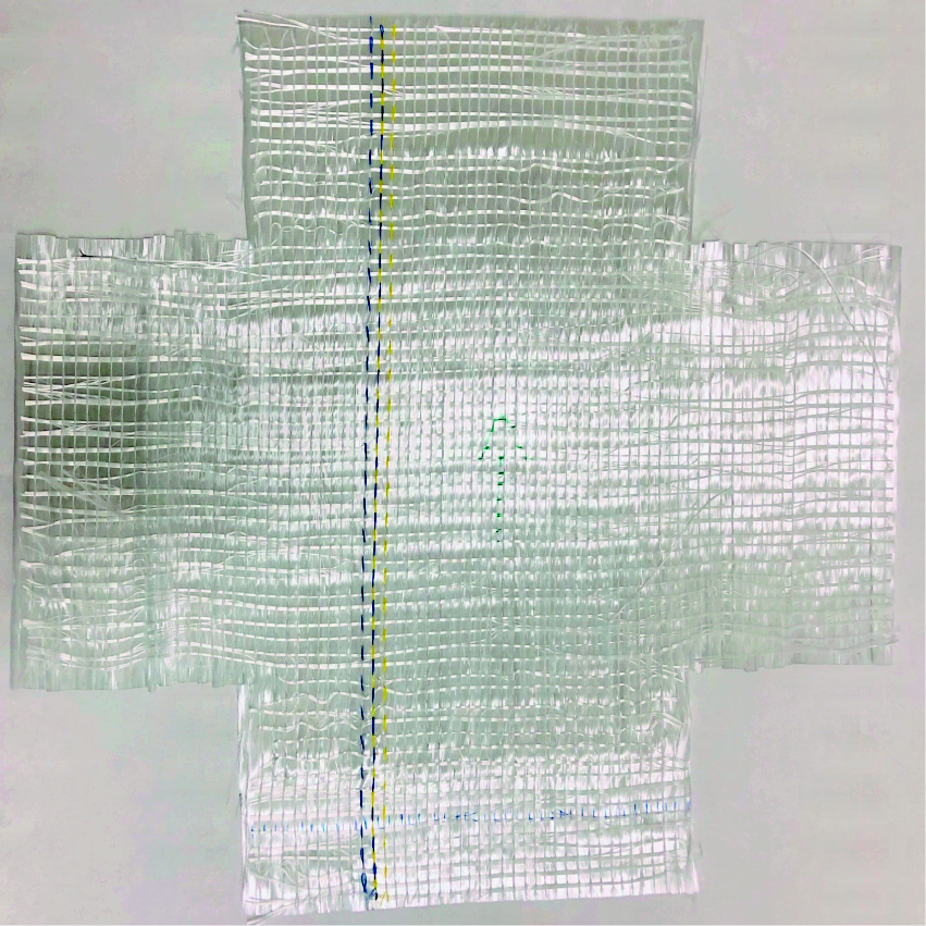
To determine the influence that the stitch has on the shear behaviour of technical textiles, two kinds of samples were prepared. In the first case, technical textiles were cut in the shape of a cross. The corners were cut out to facilitate rotation of the hinges and to avoid immediate fabric wrinkling. 28 The stitches present outside the central quadrilateral area of the sample were carefully cut by hand and the transverse rovings were removed from the edges of the cross. This was done to eliminate the influence that the transverse rovings which are not clamped might have on the shear response of the technical textile. Thus, a sample that had a central quadrilateral area with rovings running from one end to the other (samples without-stitch) was obtained. The central quadrilateral area formed the test area (Figure 3).
Samples without-stitch (w/o-stitch).
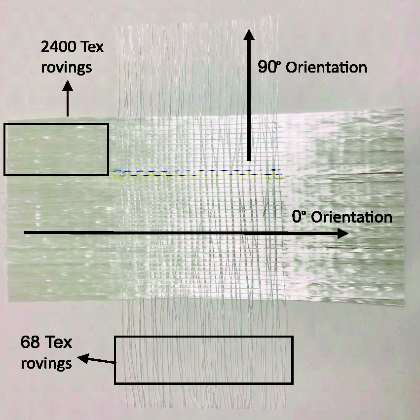
In the second case, the stitches and rovings were not removed. Hence, a unidirectional NCF sample in the shape of a cross (samples with-stitch) was obtained as shown in Figure 4.
Samples with-stitch.
The sample preparation time for both these sample types varied drastically. Each w/o-stitch sample took about 5 hours to prepare as it was labour intensive while the sample with-stitch just involved the cutting process and could be completed in a matter of a few minutes. Hence, it becomes important to know the effect that the stitch and transverse rovings have on the shear behaviour so that, if necessary, the labour intensive process could be avoided by other researchers.
Once these samples were prepared, they were stored in conditions specified by the standard EN 20139 29 for a period of 24 hours. The stored samples were then placed in the picture frame to test them in the UTM. But, before placing the material into the picture frame, it was subjected to pre-tension force with the help of the pre-tension apparatus.
Pre-tension apparatus
One of the major drawbacks of using the picture frame test is the alignment and clamping problems associated with it along with the presence of crimps while placing the material into the picture frame. In order to solve this, a pre-tension apparatus as shown in Figure 5 was developed. 26
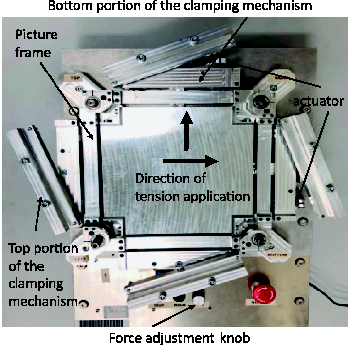
Pre-tension apparatus.
The pre-tension apparatus consists of a rectangular frame with a clamping mechanism within which the picture frame can be placed. The technical textile sample prepared was placed in the pre tension apparatus with the picture frame in it (see Figure 6(a)).
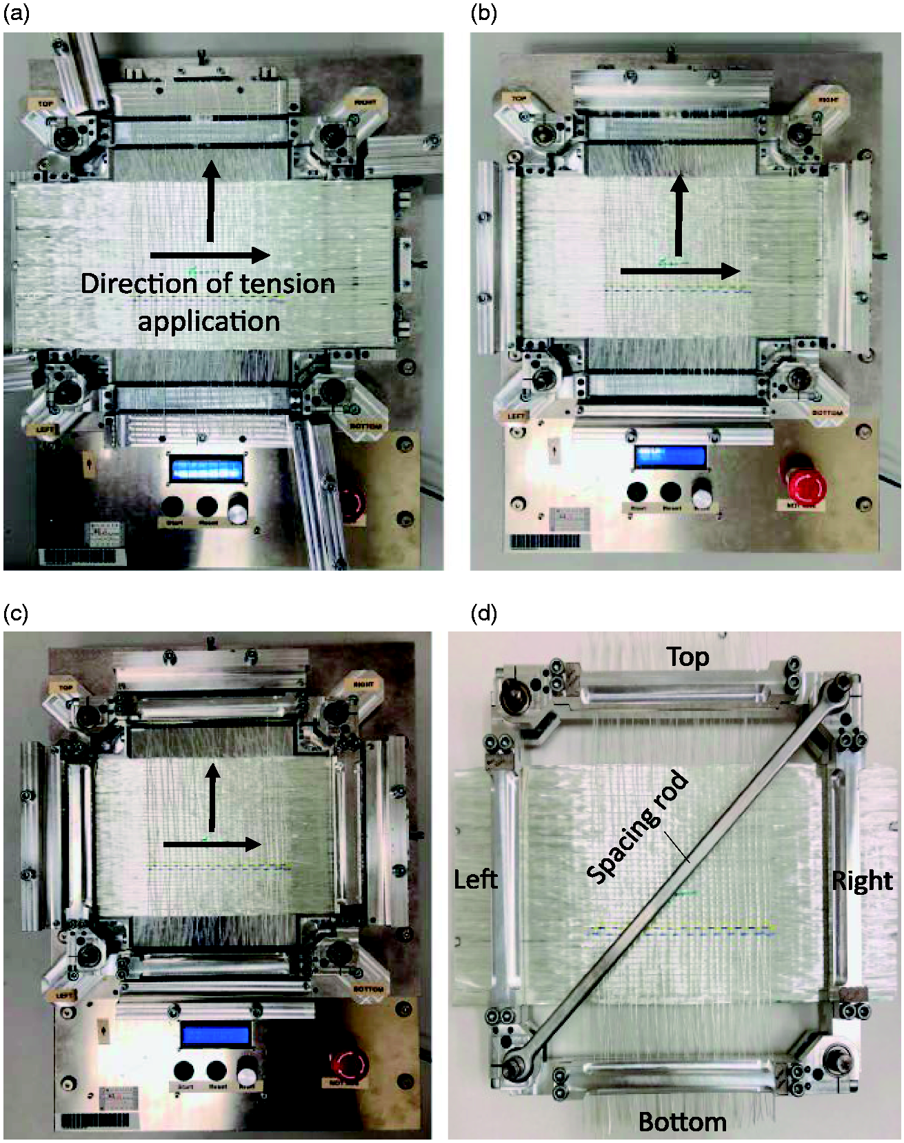
(a) Placement of sample into the pre-tension apparatus. (b) Sample clamped into the pre-tension apparatus. (c) Pre-tensed fabric held in the picture frame before removing the clamping of the pre-tension apparatus. (d) Pre-tensed sample held in the picture frame.
In the pre-tension apparatus, the bottom portion of the fabric was held in place due to the materials self-friction while, an aluminum bar secured with bolts held the top portion of the fabric as shown in the Figure 6(b). To prevent the slippage of the fibers, a rubber strip was glued to the bottom portion of the aluminium bar. A pre-determined tension (in this case about 2 N but can be adjusted between 1 N and 10 N) was then set using the force adjustment knob as shown in Figure 5 and the machine was started. The actuator moved in the direction as shown in Figure 6(a) such that it stretched both the 2400 and 68 tex rovings thereby, applying a pre-tension force of about 2 N to it.
Once the process of pre-tension was completed, the top portion of the picture frame was bolted to its bottom portion which sits in the pre-tension apparatus. The pre-tensed material was then held in the picture frame (refer Figure 6(c)). The clamping of the pre-tension apparatus was removed and a spacing rod was attached to the pivots present at the opposite ends of the picture frame and the picture frame was extracted (see Figure 6(d)). The spacing rod prevents the shearing of the textile while transporting it from the pre-tension apparatus to the UTM. The pre-tension apparatus not only helps in aligning and clamping the technical textile into the picture frame but also, removes any possible crimps present in the technical textile, thereby eliminating the drawbacks of the picture frame test. However, the pre-tension apparatus developed cannot address the problems such as bending of the yarn/rovings that occur near clamps during the process of shear testing.28,30
Testing
Based on the configuration of the technical textile used, shear test can be classified into different modes. For instance, due to the asymmetric configuration of the ±45∘ technical textile, shear test can be classified into positive and negative modes. When the material is subjected to shear test such that direction of the stitch is parallel to the Force applied (FN), the stitch is under tension and is said to be in a positive shear mode as shown in Figure 7(a). If the stitch is perpendicular to the force applied, it is under compression and is said to be in negative shear mode (refer Figure 7(b)). In case of 0/90∘ configuration, the stitch is neither parallel nor perpendicular to the force applied. Hence, the test direction is irrelevant as the stitch will always be subjected to shear and is said to be in shear mode and is illustrated in Figure 7(c). 14 As 0/90∘ technical textile is used in this particular study, the test direction becomes irrelevant.
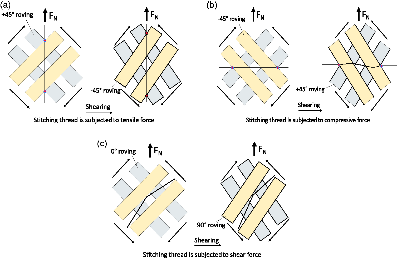
(a) Positive shear mode for ±45° technical textile. (b) Negative shear mode ±45° technical textile. (c) Shear mode for 0/90° technical textile.
The pre-tensed fabric, which is held in the picture frame along with the spacing rod is mounted onto the UTM. The bottom right corner of the frame (Figure 6(d)) is completely fixed while the top left corner is attached to a cross-head that moves at a steady rate (Figure 8). Before the experiment begins, the spacing rod is removed. The picture frame with a pre-tensed fabric is now attached to the UTM and is ready for the test. As the cross-head moves, the frame gets displaced, and the material within the frame gets deformed, shearing the material. 8 The displacements and their corresponding forces are then recorded. To eliminate the effects that the shear frame might have had on the data recorded, a different experiment with just the shear frame was carried out. The displacements and the related forces for the empty frame were noted down and this was subtracted from the actual test data (i.e. test of textile along with the frame). The resulting data was then analysed to determine the maximum shear force and the critical shear angle c experienced by the sample. The experiment was repeated for 6 samples and the values were averaged based on mean ordinate method 32 for subsequent analysis.
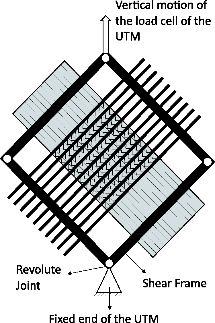
Graphical representation of the picture frame test.
The shear test was carried out to determine the influence of three different factors (presence or absence of stitch, testing speed and pre-tension force applied) on the in-plane shear behaviour of the technical textile. From the experiments, a graph of force vs. displacement was obtained.
The graph of force vs. displacement can be divided into three major regions (Figure 9). The linear region (Region I) at the beginning of the test that shows the shear behaviour of the technical textile at low forces. The middle region (Region II) constitutes the part, in which the rovings rotate about a cross-over point that controls the deformation of the technical textile. These rotations are limited by the friction between the warp (longitudinal) and weft (transverse) rovings. Therefore, the force experienced by the technical textile as a whole also depends on this friction.
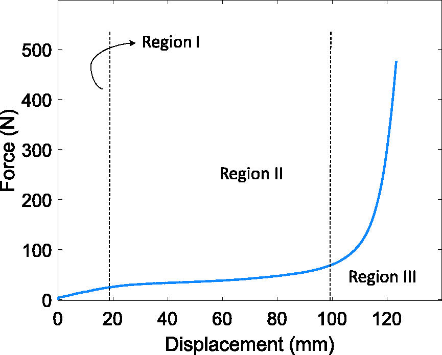
Plot of force vs. displacement.
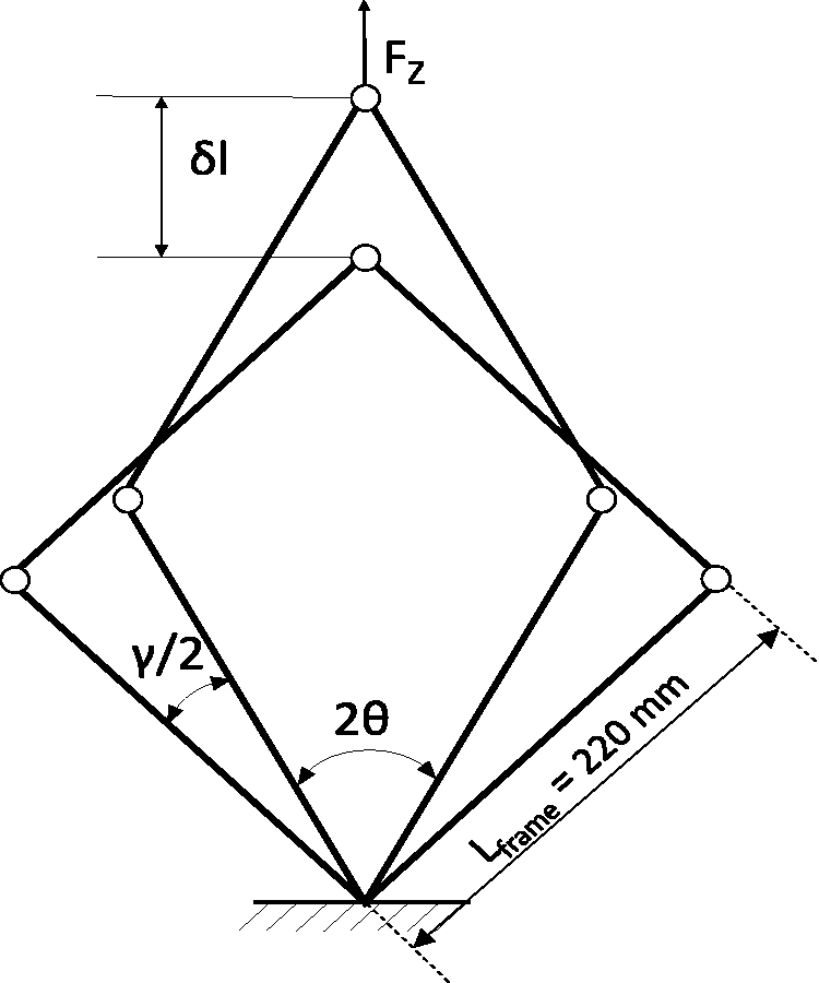
Geometry of the shear frame. 34
Eventually as the displacement increases, the rotating fibre rovings come in contact with each other, hence restricting further rotation. This leads to the tight packing of rovings increasing its stiffness and thus, the force experienced by the technical textile. This phenomenon is referred to as shear locking. The wrinkling of technical textile is due to this locking phenomenon (Region III).6,33
Assuming that the shear force experienced by the technical textile is the same as that at the revolute joints of the frame and the shear deformation across the sample is homogenous; the axial force vs. displacement curves can be converted to a plot of shear force vs. shear angle using the formulae below.
35
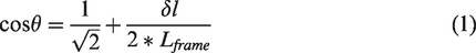

The shear angle γ (degree) is then calculated using the equation below

As there is no regulation regarding the size of the frame (LFrame) or the fabric (LFabric) to be used while carrying out the picture frame test, the size of shear frame and the fabric adopted may be diferent at different laboratories. In order to make the shear property independent of the testing apparatus employed, the shear force has to be normalized. The normalisation method based on an energy method as proposed by Peng et al.
9
is used for this pupose. The normalized shear force (FNs) is given by,
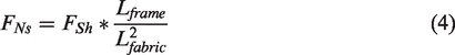
From equations (1) to (4), a plot of normalized shear force vs. shear angle can be obtained. The critical shear angle (locking angle) can then be determined by fitting linear curves into Regions II and III. The point at which these two linear lines intersect is the critical shear angle (Figure 11).
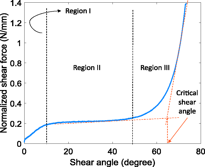
Plot of normalized shear force vs. shear angle.
The samples were subjected to the picture frame test as described in this section. The results obtained are disclosed and discussed in section “Results and Discussions”.
Results and discussions
The results obtained from the experiments are described in this section in three parts. In the first part, the effects of stitch are discussed as the time needed to prepare the samples varied significantly depending on the presence or absence of the stitch. The second part deals with the effects of testing speed. In the final part, the impact that the applied pre-tension force has on the in-plane shear behaviour of the technical textile is explained.
Effects of stitch
The shear test, as described in the subsection “Testing procedure” was carried out on two kinds of samples (w/o-stitch and with-stitch). These samples were tested at three different speeds; 100 mm/min, 50 mm/min and 25 mm/min. The effect that the stitch has on the in-plane shear behaviour of the technical textile is discussed below.
From the plots (Figure 12), it can be seen that the samples w/o-stitch have a larger shear locking angle than the samples with-stitch. However, with-stitch samples can withstand a greater amount of shear force, i.e., in order to experience a similar shear angle, the shear force acting on samples with-stitch must be higher than the ones acting on the samples w/o-stitch.
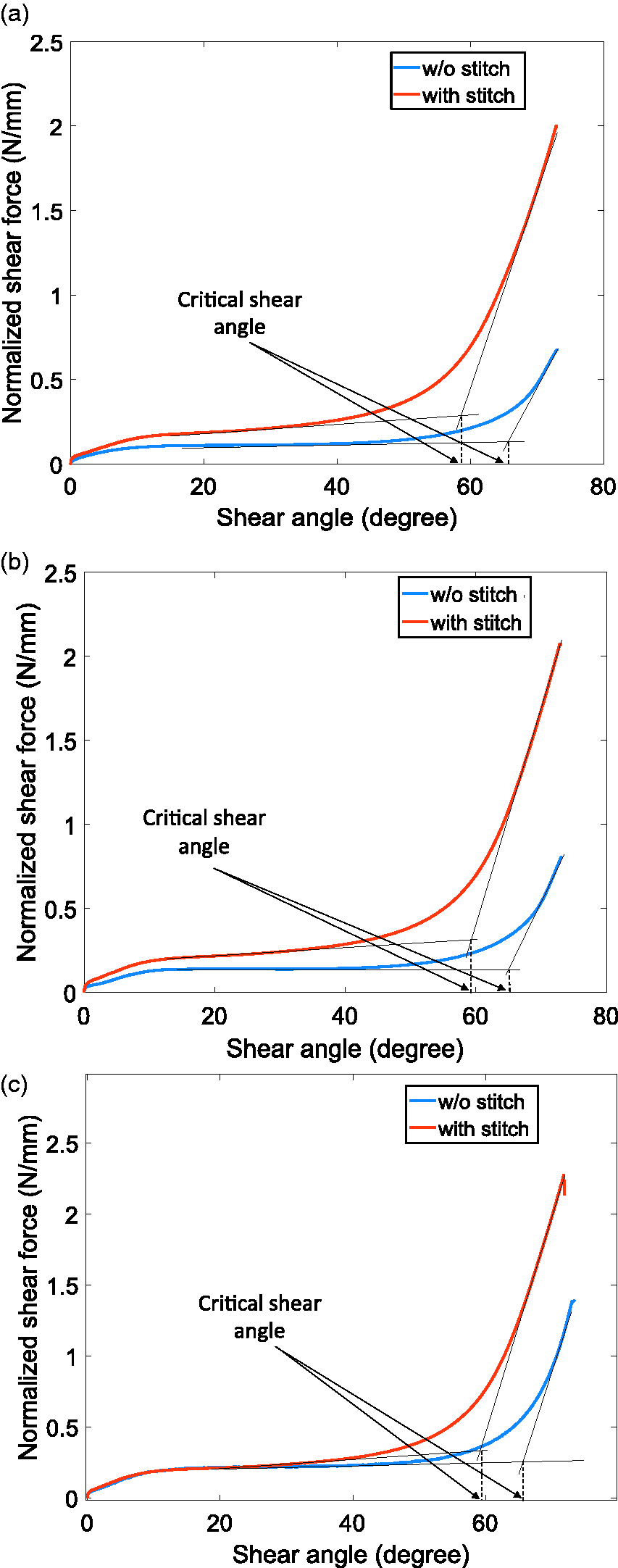
Plot of normalized shear force vs. shear angle with testing speeds of (a) 25 mm/min, (b) 50 mm/min and (c) 100 mm/min.
As the cross-head moves, the w/o-stitch sample shears within the picture frame. The adjacent rovings come in contact with each other. As there is no stitch holding the rovings together at the ends of the sample, they can rotate freely because of which the sample experiences relatively low shear forces.
In case of samples with-stitch, due to the presence of stitch at the ends of the sample, the warp and the weft roving are held together throughout the sample which limits the rotation/twisting of the rovings. This leads to a locking phenomenon which in turn leads to wrinkling of the technical textile at lower shear angles. However, the force that needs to be applied in order to achieve this wrinkling is far higher than the ones needed for samples w/o-stitch. Hence for the same sample size, samples with-stitch offers higher resistance to shear than the ones offered by the samples w/o-stitch.
The influence of stitching on the shear behaviour of the technical textile was found to be the same irrespective of the test speed.
Effects of speed
The shear test was carried out on both the types of samples at speeds of 100 mm/min, 50 mm/min and 25 mm/min. These results were compared with each other and are discussed below.
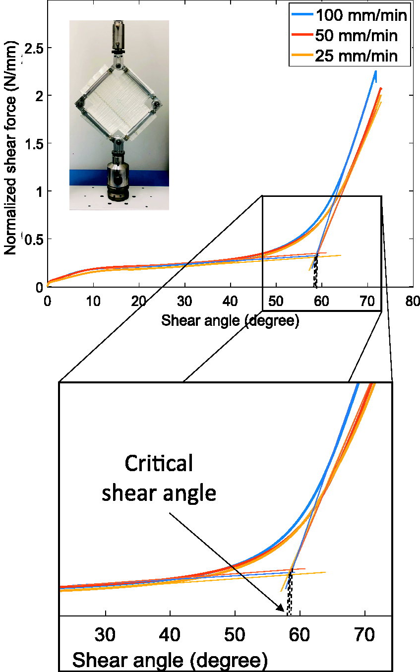
In the case of with-stitch samples, irrespective of the test speed, it was observed that the curve of normalised shear force vs. shear angle follows a similar path (Figure 13). There is not much difference in the shear force experienced by the samples with the change in the testing speed. However, the same cannot be said about the samples w/o-stitch. As the testing speed increases, so does the shear force experienced by the samples (Figure 14). However, the critical shear angle decreases slightly with the increase in the test speed for samples w/o stitch. These observations can be interpreted as follows.
Plot of normalized shear force vs. shear angle for with-stitch sample type at different testing speeds.
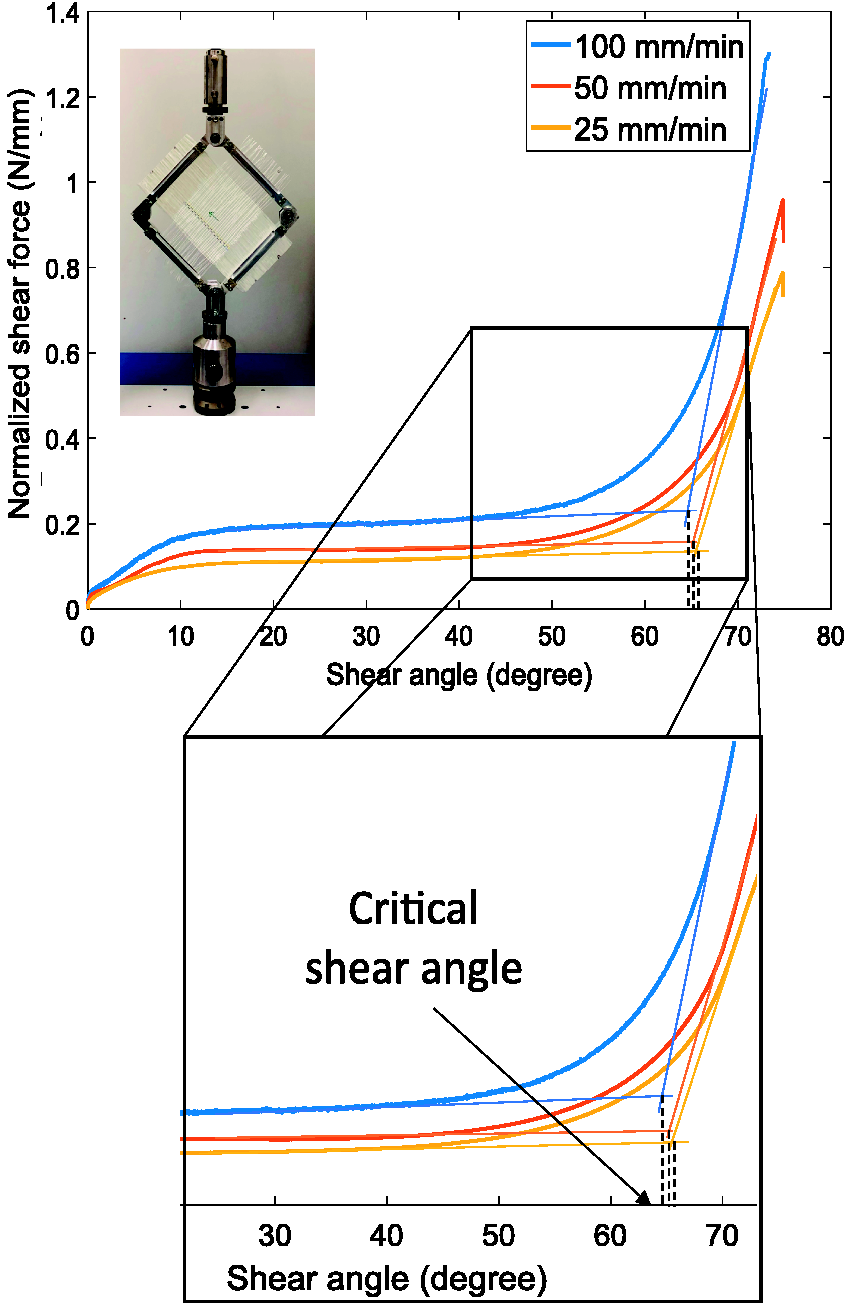
Plot of normalized shear force vs. shear angle for w/o-stitch sample type at different testing speeds.
As already established, with the test progression, the rovings rotate about their cross-over points and in time comes in contact with the adjacent rovings, thereby resulting in shear locking. In case of samples w/o stitch, as the test progresses, the free rovings present outside the test area are not bound by stitches because of which when they come in contact, they can penetrate into each other. This relaxes a certain amount of force experienced by the rovings in the test area. As the test speed increases, the time that is present for this relaxation phenomenon decreases gradually. Hence, the shear force experienced by the sample as a whole increases with the increase in the test speed. This leads to a point where the critical shear angle is reached early leading to wrinkling of the technical textile at lower shear angles (Figure 14). The same was observed in the works of Mohammed et al. 36 and Zhu et al.. 28 For the case of samples with stitch, such relaxtion phenomenon does not occur as the stitches are present throughout the sample and hence, test speed has minimal effect on its shear behaviour.
Effects of pre-tension
Samples w/o-stitch were tested for shear behaviour with the application of measured and unmeasured pre-tension force. Measured pre-tension force were applied in terms of 2 N and 10 N. The results obtained were plotted and compared with each other to determine the effect that the pre-tension force has on the shear behaviour of technical textiles (Figure 15).
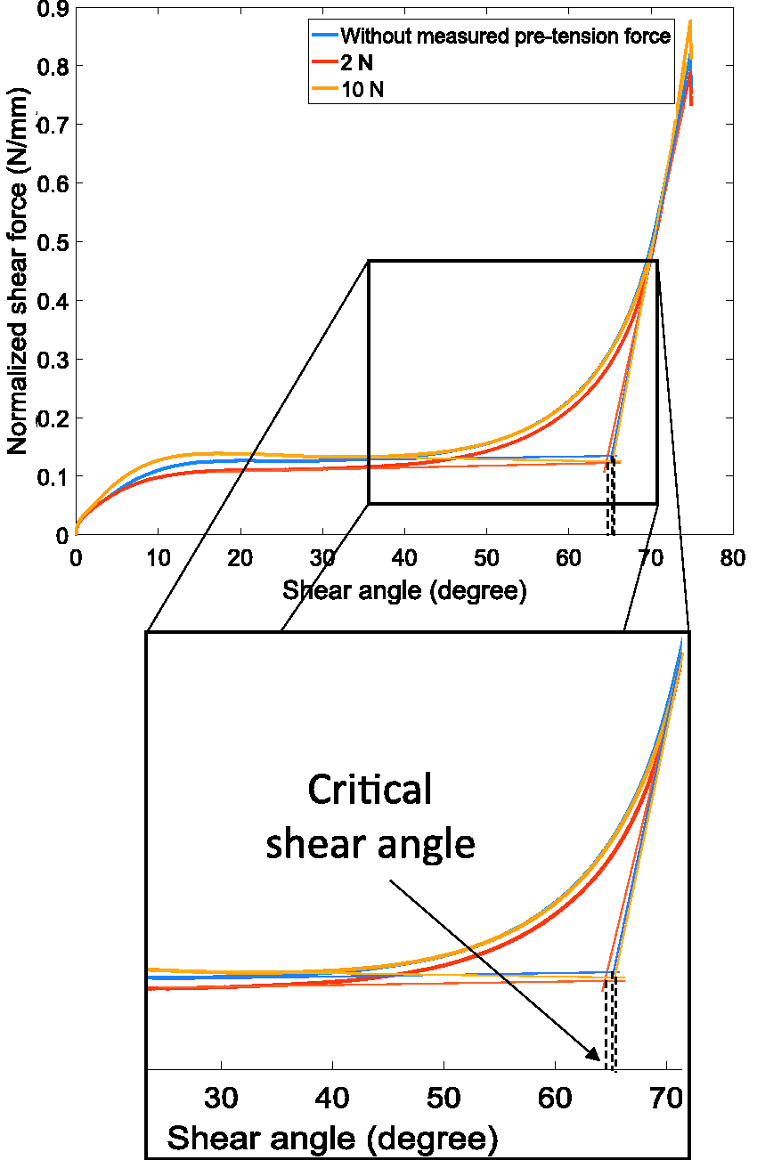
Plot of normalized shear force vs. shear angle for w/o-stitch sample type at different pre-tension force values.
Although at first look, it seems like there is no significant difference in the results obtained; upon closer inspection, it can be observed that the maximum shear force experienced by the technical textile increases with the increase in the applied pre-tension force. This is due to the amount of pre-tension force acting on the technical textile.
Also, the shear force marginally increases with the increase in pre-tension force from 2 N to 10 N. The plot of normalized shear force vs. shear angle for samples that were placed into the picture frame without the help of the pre-tension apparatus lies between the ones tested with values of 2 N and 10 N. These samples experience pre-tension force due to the aligning and the clamping process that is carried while placing the textile into the picture frame. The amount of pre-tension force applied cannot be controlled in this particular case. Hence, it can be concluded that the pre-tension force experienced by these samples when in frame was somewhere between 2 N and 10 N as there is no definitive way of measuring it, once the sample is in the picture frame. The difference in the critical shear angle obtained for these samples is negligible as the sample type used and the speed at which the tests were conducted were same for all the samples.
Proposal of a reference shear test
From the results obtained in section “Results and Discussions”, a reference shear test using Trellis picture frame having the following specifications for the sample is proposed.
Type – Sample without stitch is recommended to be used for the test. Although the sample preparation for this type is labour intensive and time consuming, this particular configuration is proposed as it has a quadrilateral test area and hence an even distribution of shear force in the sample. Also, it was observed that the resistance to shear in this particular configuration was low which in turn helps drapability. So, using this configuration for testing will throw more light on the extent to which a material can be sheared and draped before it wrinkles. Speed – When a speed of 100 mm/min is used it helps to gain knowledge about draping of technical textiles at high speeds. This allows for faster draping of technical textile onto the mould and hence reduced production times. However, when a speed of 25mm/min is used, the distinction between different shear phases is more pronounced and the critical shear angle can be identified easily. So, depending on the application, either one of them can be used. Pre-tension force – A certain amount of pre-tension force has to be applied in order to eliminate the presence of crimps while placing the sample onto the picture frame. The value of pre-tension force applied must not be too high that it alters the shear properties of the technical textile but not too low that it does not remove any crimps. Hence, a suitable value of pre-tension force must be used, ideally between 2 N–4 N.
Conclusion
Shear test using a Trellis picture frame was carried out on two different types of 0/90∘ technical textile samples (samples w/o-stitch and samples with-stitch), to determine the effect that factors such as stitch (presence or absence of it), testing speed and pre-tension force have on the in-plane shear behaviour of technical textiles. The results are used to propose a reference test. From the results obtained, it can be concluded that
Samples w/o-stitch had a greater shear locking angle and the force required to achieve this locking angle was less when compared to samples with-stitch. Hence, with-stitch samples have a higher resistance to in-plane shear behaviour. Therefore, the presence of stitch significantly affects the force that the technical textile can resist before shearing. Both the types of samples were tested at different test speeds, i.e., 100 mm/min, 50 mm/min and 25 mm/min. It was observed that, for with-stitch samples, irrespective of the test speed, the curve of normalized shear force vs. shear angle was almost the same. However, in the case of samples w/o-stitch, the shear force experienced by the sample increased with the increase in the test speed. The critical shear angle decreased with the increase in test speed for w/o-stitch samples. The presence of stitch nullifies the effect that the testing speed has on the shear behaviour of the technical textile. Therefore, during the process of handling technical textile without stitches/missing stitches, the speed at which the technical textile is draped becomes an essential factor. Finally, the samples w/o-stitch were tested to determine the effect that the pre-tension force has on its shear behaviour. As the pre-tension force increased from 2 N to 10 N, there was a marginal increase in the shear force experienced by the textile for similar shear angles. The critical shear angle decreased with the increase in the value of the applied pre-tension force. However, this decrease was minimal and can be ignored. The curve for the samples tested with the application of unmeasured pre-tension force was between the ones for 2 N and 10 N.
For a 0/90∘ technical textile configuration, a reference shear test using Trellis picture frame with samples having the stitch type of without-stitch sample, a speed of 100 or 25 mm/min and a pre-tension force in the range of 2 N–4 N is proposed based on the above mentioned conclusions.
Footnotes
Acknowledgements
The authors are grateful to SAERTEX GmbH & Co.KG for supplying the material for testing. The authors would also like to thank Mr. Torben Reck for his assistance during the process of sample preparation and experimental testing.
Declaration of Conflicting Interests
The author(s) declared no potential conflicts of interest with respect to the research, authorship, and/or publication of this article.
Funding
The author(s) disclosed receipt of the following financial support for the research, authorship, and/or publication of this article: The authors are grateful for the financial support provided by the Deutsche Forschungsgemeinschaft (DFG; Grant number - OH 289/2-1; TH 798/12-1).